


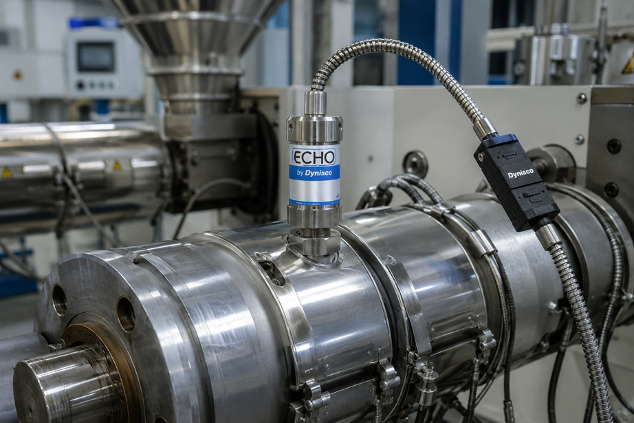
A melt pressure sensor can be mechanically installed correctly in an extruder and still provide an incorrect, unstable or no measured value at all. In such cases, the cause is often not the measuring diaphragm or the pressure sensor itself, but the electrical connection between the sensor, connection cable and evaluation electronics.
Correct wiring is particularly important with melt pressure sensors. A conventional mV/V sensor only provides a very small bridge signal, whereas a 4…20 mA transmitter can transmit the supply and measurement signal through the same current loop. If these two concepts are confused, an electrically compatible connector can still be wired completely incorrectly.
Extrusion systems also contain typical sources of interference: heater bands, motors, frequency converters, contactors and long cable runs generate electromagnetic interference. Incorrect shielding, signal cables routed parallel to power cables or additional ground connections can therefore cause fluctuating measured values even though the sensor itself is operating correctly.
Before connecting a melt pressure sensor, the output signal, supply voltage, specific pin assignment, evaluation input and shielding must therefore always be checked together.
A good example is the Dynisco Echo™ Series offered by ICS Schneider. It is designed for typical extrusion applications and, depending on the configuration, is available with 3,33 mV/V, 0…10 VDC or 4…20 mA. This product family clearly demonstrates why an identical or similar connector can have a different pin assignment depending on the electrical version.
Additional solutions can be found under Dynisco Products at ICS Schneider and under Dynisco Melt Pressure Sensors.
Table of Contents
- Why the connector alone says nothing about the wiring
- Distinguishing mV/V, 4…20 mA and voltage outputs
- How is an mV/V melt pressure sensor connected?
- How is a 4…20 mA melt pressure transmitter connected?
- How is a voltage output connected?
- Pin assignment of the Dynisco Echo™ Series
- What are the R-Cal connections used for?
- Connecting the shielding correctly
- Do not confuse shielding with functional earth
- Routing signal cables correctly on the extruder
- Considering cable and electronics temperature
- Correctly installing and checking connectors
- Continuity testing without damaging the sensor
- Electrically testing an mV/V sensor
- Testing a 4…20 mA current loop
- Connection to PLC or display
- Typical error patterns
- Recommended commissioning procedure
- Practical example: No measured value after replacing the sensor
- Dynisco Echo™ Series at ICS Schneider
- Conclusion
- FAQ
Why the connector alone says nothing about the wiring
A common mistake with melt pressure sensors is to look only at whether the mechanical connector fits. Two sensors can have the same 6-pin connector and still operate completely differently electrically.
The decisive factor is the output signal.
A sensor with:
3,33 mV/V
requires bridge excitation and has separate wires for excitation and measurement signal.
A transmitter with:
4 … 20 mA
can, by contrast, be designed as a two-wire system in which the same two conductors are used both for the power supply and for transmitting the measurement signal.
With a voltage output such as:
0 … 10 VDC
the supply and output signal are again separate.
The question “Which pin is positive?” can therefore only be answered once the exact electrical sensor version is known.
Distinguishing mV/V, 4…20 mA and voltage outputs
| Output | Basic principle | Typical evaluation | Special feature |
|---|---|---|---|
| 3,33 mV/V | Strain-gauge Wheatstone bridge | Melt pressure display, controller or measuring amplifier | Very small signal, separate bridge excitation required |
| 4…20 mA | Amplified current output | PLC, DCS, display | With two-wire versions, supply and signal use the same conductors |
| 0…10 VDC | Amplified voltage output | PLC, display, data logger | Separate supply and signal line |
When replacing a sensor, it is therefore not sufficient to check only whether the:
- measuring range,
- process thread,
- stem length,
- temperature range
are suitable.
Just as important is:
sensor output signal = evaluation electronics input signal
How is an mV/V melt pressure sensor connected?
A conventional melt pressure sensor with an mV/V output operates with a Wheatstone measuring bridge. The evaluation electronics supply this bridge with a stable DC voltage and then measure the very small differential voltage at the signal output.
For the Dynisco Echo™ Series, the output sensitivity is:
3,33 mV/V
and Dynisco recommends for the mV/V version:
10 VDC bridge excitation
with a maximum of:
12 VDC
What does 3,33 mV/V mean?
The output voltage is proportional to the excitation voltage.
With:
10 V excitation
and:
3,33 mV/V
the approximate full-scale output is:
3,33 mV/V × 10 V = 33,3 mV
This shows how small the signal is.
Electromagnetic interference or unfavorable ground connections can therefore have a comparatively large influence on the measurement result.
An mV/V sensor requires four functional conductors
- excitation +,
- excitation –,
- signal +,
- signal –.
For sensors with internal shunt calibration, two additional conductors are required for the R-Cal function.
How is a 4…20 mA melt pressure transmitter connected?
With a 4…20 mA transmitter, the sensor signal is already electronically amplified and converted into an industrial current signal.
The corresponding Echo configuration uses a two-wire connection.
The two conductors simultaneously carry:
power supply + measurement signal
The current loop basically consists of
- DC power supply,
- melt pressure transmitter,
- analog input or display,
- connecting cables.
All components must be electrically connected as a closed current loop.
The measurement current within the operating range is:
4 … 20 mA
For the Echo Series
the mA version requires a supply of:
14 … 36 VDC
.
Important
A 4…20 mA two-wire sensor is not wired like an mV/V sensor with four conductors for excitation and signal.
If separate “signal wires” are being sought on a two-wire transmitter, the measuring chain is already being wired according to the wrong principle.
How is a voltage output connected?
A melt pressure sensor with an amplified voltage output also requires auxiliary power, but it additionally has a separate signal output.
The Echo Series is available, among other options, with:
0 … 10 VDC
.
For the VDC versions, Dynisco specifies a supply of:
16 … 36 VDC
.
Electrically, the connection structure is therefore more similar to the mV/V sensor than to the two-wire current transmitter:
- supply +,
- supply –,
- signal +,
- signal –.
The decisive difference is that the output signal is already amplified and is therefore no longer in the millivolt range.
Pin assignment of the Dynisco Echo™ Series
For the Echo Series with a 6-pin connector, Dynisco specifies a defined pin assignment for the different output versions.
| Pin | mV/V and VDC | 4…20 mA |
|---|---|---|
| A | Signal + | Signal + / Supply + |
| B | Signal – | Signal – / Supply – |
| C | Excitation + | not connected |
| D | Excitation – | not connected |
| E | internal R-Cal | internal R-Cal |
| F | internal R-Cal | internal R-Cal |
This makes the difference particularly clear
For the mV/V or VDC version, the pins:
A / B = signal
and:
C / D = excitation
are used.
For the 4…20 mA version, by contrast:
A / B = supply and signal
are used together.
Pins C and D remain unconnected with this version.
Important when replacing sensors
The pin assignment must not be copied solely because a 6-pin connector is already present. Before connection, the nameplate, output code and data sheet of the specific sensor must be checked.
What are the R-Cal connections used for?
Many Dynisco melt pressure sensors feature internal shunt calibration referred to as:
R-Cal
.
On the Echo Series, this function is connected to:
Pin E and Pin F
.
According to Dynisco, the internal R-Cal simulates a signal of approximately:
80 % FSO
or:
80 % of measuring span
What is this useful for?
Shunt calibration can be used to check whether the electrical measuring chain is operating plausibly.
With R-Cal activated, the:
- sensor,
- cable,
- measuring amplifier or analog input,
- scaling
should produce a defined value.
Example
For a measuring range of:
0 … 500 bar
80 % of the measuring span ideally corresponds to:
400 bar
However
R-Cal is not a pressure calibration of the complete mechanical measuring system.
The function checks the electrical measuring chain and simulates a defined sensor signal. It does not replace calibration using a traceable pressure reference.
Connecting the shielding correctly
The small output signal of an mV/V sensor is particularly sensitive to electromagnetic interference. Dynisco therefore requires the use of a shielded cable for the Echo Series.
The shield should be
grounded at one end only
Why?
If both ends of the shield are connected to different ground potentials, an equalizing current can flow through the shield.
This can create a:
ground loop
.
This in turn can couple interference voltages into the measurement line.
With original Dynisco cable assemblies
Dynisco points out that the shield may already be connected to the sensor-side mating connector.
In this case, the shield should not additionally be connected again at the instrument.
Therefore
The specific shield connection must match the cable assembly being used. Do not simply connect both cable ends to PE.
Do not confuse shielding with functional earth
The cable shield is not automatically:
Signal –
and it is also not automatically:
Supply –
.
It must also not be used as an additional return conductor without checking the wiring diagram.
Four different functions must be considered separately
- excitation or supply,
- measurement signal,
- shielding,
- protective or functional earth.
A typical error
is to connect signal negative simultaneously to:
- control system ground,
- machine housing,
- cable shield
.
This can create unwanted additional current paths.
Routing signal cables correctly on the extruder
An extrusion system contains numerous electrical sources of interference. Cable routes close to the following are particularly critical:
- motor cables,
- frequency converters,
- heater band cables,
- contactors,
- transformers,
- power busbars.
Signal cables should therefore
- be routed as far away from power cables as possible,
- cross power cables at right angles wherever possible,
- not be routed together with AC power cables in the same cable duct,
- be mechanically protected against abrasion and crushing.
For particularly interference-sensitive mV/V signals
twisted conductor pairs are also useful because they help reduce inductively coupled interference.
Considering cable and electronics temperature
The measuring diaphragm of a melt pressure sensor is located directly in the hot polymer process. However, the electrical connector and electronics must not automatically be exposed to the same temperature.
For the Echo Series, ICS and Dynisco specify
a maximum electronics temperature for the mV/V version of:
120 °C
and for the mA or VDC versions a maximum of:
85 °C
The permissible diaphragm temperature, by contrast
can be significantly higher depending on the mechanical version.
This demonstrates
Process temperature, electronics temperature and permissible cable temperature are three different values.
The permissible cable temperature must be taken from the specification of the actual cable assembly being used.
In practice, the following should be avoided
- placing cables directly on heater bands,
- positioning connectors directly against hot barrel surfaces,
- fastening cables to hot piping,
- installing flexible cables under tension or with a tight bending radius.
Correctly installing and checking connectors
A poor connector contact can cause the same symptoms on a melt pressure sensor as a defective sensor.
Before connecting, the following should therefore be checked
- correct connector type,
- correct orientation or keyway,
- clean contacts,
- no bent pins,
- no polymer, oil or dirt residues,
- no corrosion,
- secure strain relief.
Particularly important
The connector must not be aligned using the contacts or forcibly twisted.
The keying geometry must be correctly aligned before the connector halves are joined.
Continuity testing without damaging the sensor
If a cable break is suspected, a continuity test is useful. However, it should first be performed on the disconnected connection cable and not blindly across the complete connected sensor electronics.
A suitable procedure is
- Switch off power to the sensor and evaluation electronics.
- Disconnect the cable at both ends.
- Check each conductor individually from the connector pin to the connection end.
- Check adjacent conductors for unintended short circuits.
- Check the shield against the signal conductors.
- Carefully move the connector during the measurement to detect intermittent cable breaks.
Important for mV/V sensors
A Wheatstone bridge has defined electrical resistances between its terminals.
A resistance reading between several sensor pins therefore does not automatically mean:
short circuit
For the Echo Series
a bridge resistance of at least:
345 Ω
is specified for the mV/V version.
Therefore
A simple continuity test directly on the sensor must be interpreted using the electrical circuit diagram.
An insulation tester with a high test voltage should not be connected to the sensor electronics without explicit manufacturer approval.
Electrically testing an mV/V sensor
If an mV/V sensor does not provide a plausible measured value, the measuring chain should be checked systematically.
1. Check bridge excitation
The voltage specified by the manufacturer must be present between the excitation pins.
For the Echo Series:
Pin C ↔ Pin D
with typically:
10 VDC
2. Check polarity
Reversed excitation or signal conductors can result in:
- a negative measured value,
- incorrect direction,
- implausible zero point
.
3. Measure the signal
The differential signal is present between:
Pin A ↔ Pin B
and is only in the millivolt range.
4. Activate R-Cal
The internal shunt calibration can be activated via pins E and F.
If the display responds plausibly to R-Cal, important parts of the electrical signal chain are functioning.
5. Check the display or amplifier
The input must be suitable for a strain-gauge bridge sensor or the specific mV/V signal.
A standard:
0 … 10 V PLC input
cannot directly and correctly evaluate a:
3,33 mV/V bridge signal
.
Testing a 4…20 mA current loop
A 4…20 mA transmitter is tested differently from an mV/V sensor.
On the Echo Series
supply and measurement signal are both connected to:
Pin A = +
and:
Pin B = –
For troubleshooting, the following should be checked
- is the required supply voltage present?
- is the current loop completely closed?
- is the PLC input correctly configured as a current input rather than a voltage input?
- is the polarity correct?
- is the loop current actually within the expected range?
A current meter
is connected in a 4…20 mA loop:
in series
.
It would be incorrect
to connect an ammeter in parallel directly across the supply in the same way as a voltmeter.
This can result in a very low internal resistance and damage the loop or measuring instrument.
Connection to PLC or display
Before connecting to a PLC, the input type of the existing module must first be determined.
A PLC analog input for 4…20 mA
can directly process a corresponding melt pressure transmitter if the:
- supply,
- load resistance,
- wiring,
- potential reference
are compatible.
An mV/V sensor
normally requires dedicated strain-gauge evaluation electronics.
These provide:
- bridge excitation,
- amplification,
- zero adjustment,
- scaling,
- shunt calibration where applicable.
For PLC scaling
it must also be clearly defined that:
4 mA = measuring range start
and:
20 mA = measuring range end
Example
For a sensor with:
0 … 500 bar = 4 … 20 mA
the following applies:
12 mA ≈ 250 bar
Typical errors when connecting melt pressure sensors
| Observation | Possible cause | Recommended check |
|---|---|---|
| No indication | No supply or open current loop | Check supply and cable continuity |
| 4…20 mA sensor wired with four conductors like an mV/V sensor | Signal principle confused | Check output code and pin assignment |
| mV/V sensor connected directly to PLC | Unsuitable analog input | Use a strain-gauge measuring amplifier or suitable display |
| Measured value is negative | Signal polarity reversed | Check Signal + and Signal – |
| Measured value fluctuates when the motor is running | EMC interference | Check shielding and cable routing |
| Measured value jumps when a heater band is switched on | Signal cable routed unfavorably next to a power cable | Change cable route and check shielding concept |
| Measured value drifts after prolonged operation | Electronics or cable thermally stressed | Check temperature in the connection area |
| R-Cal works, but actual pressure value is incorrect | Electrical chain basically functional; mechanical or process-side problem possible | Check sensor, mounting bore and actual process pressure |
| R-Cal produces an incorrect value | Incorrect scaling, wiring error or evaluation problem | Check R-Cal pins, measuring range and scaling |
| Indication permanently at full scale | Wiring error, incorrect excitation or incorrect input type | Check output signal directly |
| Signal drops out when the cable is moved | Cable break or poor connector contact | Check continuity while carefully moving the cable |
| Interference disappears when a ground connection is disconnected | Possible ground loop | Check single-ended shielding and equipotential bonding |
Recommended commissioning procedure
- Clearly identify the sensor: Read the type, output signal and complete order code.
- Check the data sheet: Determine the supply voltage, connector type and specific pin assignment.
- Identify the evaluation device: Check whether the input is designed for mV/V, 4…20 mA or voltage.
- Switch off the supply: Do not carry out wiring work with the measuring chain energized.
- Check the connector: Inspect pins, keyway, contacts and strain relief.
- Check the cable: Test continuity of each conductor and possible short circuits.
- Verify the shielding: Determine at which side the shield is already connected.
- Separate signal and power cables: Ensure EMC-compliant cable routing.
- Wire according to the pin assignment: Do not work according to cable color alone; assign pins according to their function.
- Switch on the supply: Check the voltage directly at the measuring point.
- Check the zero signal: Bring the system to operating temperature and ensure a pressure-free condition.
- Test R-Cal: Check the electrical measuring chain for a plausible 80 % value.
- Check scaling: Compare the sensor measuring range with the display or PLC.
- Start the extruder in a controlled manner: Observe the development of the measured value.
- Observe interference effects: Switch motors, heaters and other loads and monitor the measurement signal for changes.
- Document the wiring: Record pin assignment, cable colors, terminals and shield connection.
Practical example: No measured value after replacing the sensor
An old melt pressure sensor on an extruder is replaced. The mechanical connection fits and the new sensor can be installed without difficulty. After switching on, however, the machine control system does not display a plausible pressure value.
Because the new sensor has the same 6-pin connector, it was initially assumed that the existing cable assignment could be retained unchanged.
During the check, however, it becomes apparent that the previous sensor provided a:
3,33 mV/V signal
.
The newly installed sensor instead has:
4 … 20 mA
The existing wiring was therefore electrically unsuitable
The old measuring chain used:
A/B = signal
and:
C/D = bridge excitation
The new two-wire transmitter instead requires
A/B = supply and signal
while:
C/D are not used
In addition
the existing controller was designed for an mV/V bridge signal and could not directly evaluate the 4…20 mA transmitter.
After correction
the 4…20 mA sensor is connected to a suitable current input and scaled according to the pressure measuring range.
The R-Cal function is then used to check the electrical measuring chain.
Result
The mechanically compatible connector had suggested electrical compatibility that was not actually present. Only checking the signal type, supply and pin assignment led to the correct solution.
Dynisco Echo™ Series at ICS Schneider
For general melt pressure measurement and extrusion applications, ICS Schneider offers the:
Dynisco Echo™ Series – Melt Pressure Sensor / Melt Pressure Transducer
as a dedicated product.
The series is particularly relevant to the subject of wiring
because different electrical output versions are available within the same product family.
ICS specifies, among other things
- 3,33 mV/V,
- 0…10 VDC,
- 4…20 mA,
- 6-pin electrical connection,
- optional integrated temperature sensor,
- internal 80 % shunt calibration,
- measuring system with strain-gauge Wheatstone bridge,
- TiAlN-coated diaphragm,
- various process connections for typical extrusion applications.
The supply depends on the output version
| Echo output | Supply |
|---|---|
| 3,33 mV/V | 10 VDC recommended, maximum 12 VDC |
| 4…20 mA | 14…36 VDC |
| VDC output | 16…36 VDC |
Also particularly relevant to the electrical installation
are:
- shielded cable,
- single-ended shield connection,
- correct assignment of pins A to F,
- separation of signal and power cables,
- observance of the permissible electronics temperature.
The Echo Series is therefore particularly suitable
for applications in which the sensor is to be selected to match an existing:
- melt pressure display,
- controller,
- PLC,
- process data acquisition system
.
Conclusion
The electrical integration of a melt pressure sensor does not begin with connecting the individual conductors, but with clearly identifying the sensor version. A mechanically compatible connector does not guarantee a compatible electrical pin assignment.
It is particularly important to distinguish between:
mV/V ↔ voltage output ↔ 4…20 mA
because both the supply and the pins used depend on this distinction.
With the Dynisco Echo™ Series
for mV/V or VDC:
A/B are used for the signal and C/D for excitation
.
With the 4…20 mA two-wire signal, by contrast:
A/B are used jointly for supply and signal
Shielding is also part of the measuring chain
Dynisco requires a shielded cable and grounding of the shield at one end only. Particularly with mV/V signals, low-interference cable routing is essential for stable measured values.
R-Cal simplifies troubleshooting
A defined internal calibration signal can be generated via pins E and F. This allows the sensor connection, cable and evaluation system to be checked for plausibility without applying actual process pressure.
Temperature must also be considered
The measuring diaphragm can be exposed to significantly higher temperatures than the electronics, connector and connection cable. Cables and connectors must therefore not simply be routed directly next to hot extruder components.
For practical applications
Identify the sensor version → check the output signal → determine the supply voltage → check the pin assignment for the specific version → select a suitable PLC or controller input → test the cable before connection → verify the shielding → route signal and power cables separately → connect the connector correctly → check the supply → verify the zero signal → test R-Cal → check scaling → commission the extruder in a controlled manner → observe the measurement signal for interference under actual operating conditions → document the wiring.
FAQ: Correctly Connecting and Wiring Melt Pressure Sensors
Can I simply replace two Dynisco sensors with the same connector?
Not automatically. The output signal, supply voltage and pin assignment must also match.
Which output signals does the Dynisco Echo™ Series offer?
ICS specifies 3,33 mV/V, 0…10 VDC and 4…20 mA.
Which supply does the mV/V version require?
Dynisco recommends 10 VDC and specifies 12 VDC as the maximum value.
Which supply does the 4…20 mA version require?
14…36 VDC is specified for the Echo Series.
Which supply does the voltage output version require?
Dynisco specifies 16…36 VDC for the VDC version.
Which pins are used on the Echo mV/V sensor?
Pin A is Signal +, Pin B is Signal –, Pin C is Excitation + and Pin D is Excitation –.
Which pins are used on the Echo 4…20 mA version?
Pin A is Signal + or Supply + and Pin B is Signal – or Supply –. Pins C and D are not used for the current output version.
What are pins E and F used for?
They are used for the internal R-Cal or shunt calibration function.
What does R-Cal do?
With the Echo Series, a signal of approximately 80 % of the measuring span is simulated in order to check or scale the electrical measuring chain.
Does R-Cal replace pressure calibration?
No. R-Cal simulates an electrical sensor signal and does not verify the complete mechanical pressure measuring chain using an actual reference pressure.
Why does an mV/V sensor require a separate excitation voltage?
The sensor signal is generated in a Wheatstone measuring bridge. This bridge must be supplied with a stable excitation voltage.
Can a 3,33 mV/V sensor be connected directly to a standard PLC input?
Normally not to a conventional 4…20 mA or 0…10 V input. Suitable strain-gauge evaluation electronics or a measuring amplifier are required.
Can a 4…20 mA melt pressure sensor be connected directly to a PLC?
Yes, provided a suitable 4…20 mA input is available and the supply, load resistance, potential reference and scaling are correctly designed.
Why does a 4…20 mA two-wire sensor have only two active connection wires?
Because the supply and measurement signal are transmitted through the same current loop.
How is an ammeter connected in a 4…20 mA loop?
It is connected in series in the current loop.
Why must I not simply connect an ammeter in parallel across the supply?
A current meter has a very low internal resistance and can therefore cause a short circuit or an impermissible load.
Does the cable have to be shielded?
Dynisco requires a shielded cable for the Echo Series.
Where should the cable shield be grounded?
Dynisco specifies grounding at one end only. With original Dynisco cable assemblies, it must be taken into account that the shield may already be connected to the sensor-side mating connector.
Why should the shield not be grounded at both ends?
Equalizing currents can flow between different ground potentials, causing a ground loop and additional interference.
Is the cable shield the same as Signal –?
No. Shield, signal negative and supply negative have different functions and must not be interconnected without checking the circuit diagram.
Why does my melt pressure signal fluctuate when the extruder motor is running?
Possible causes include electromagnetic interference, unfavorable cable routing, incorrect shielding or potential differences.
Can the sensor cable be routed together with motor cables?
This should be avoided. Dynisco recommends that signal cables are not routed together with AC power cables.
Can heat influence the electrical signal?
Yes. Electronics, connectors and cables have their own temperature limits, which can be lower than the permissible diaphragm or process temperature.
What maximum electronics temperature does Dynisco specify for Echo mV/V?
A maximum of 120 °C is specified for the mV/V version.
What maximum electronics temperature applies to Echo mA and VDC?
A maximum of 85 °C is specified for the mA and VDC versions.
Can I place the sensor cable on a heater band?
This should be avoided. The permissible cable temperature of the specific cable assembly must be observed.
How do I check for a cable break?
With the cable de-energized and disconnected at both ends, each conductor can be checked individually for continuity and for short circuits to adjacent conductors or the shield.
Why does my continuity tester show resistance between several mV/V sensor pins?
An mV/V sensor contains a Wheatstone measuring bridge. Electrical connections or resistances between the bridge terminals are therefore inherent in the design.
What bridge resistance does ICS specify for the Echo mV/V version?
ICS specifies at least 345 Ω.
Should I connect an insulation tester directly to the sensor?
Not without explicit manufacturer approval. High test voltages can damage the sensor electronics.
What does a correct R-Cal signal mean if the actual process value is still incorrect?
It means that the electrical measuring chain is at least basically operating plausibly. The mechanical installation, mounting bore, diaphragm and actual process pressure should then also be checked.
What is most important when replacing a sensor?
In addition to the pressure range and mechanical connection, the output signal, supply, connector type, pin assignment, temperature specification and evaluation electronics must all be compatible.
Where can I find the Dynisco Echo™ Series at ICS Schneider?
Further information can be found under Dynisco Echo™ Series – Melt Pressure Sensor / Melt Pressure Transducer at ICS Schneider.
Where can I find additional Dynisco melt pressure sensors?
An overview can be found under Dynisco Melt Pressure Sensors at ICS Schneider.
Where can I find additional Dynisco products?
An overview can be found under Dynisco Products at ICS Schneider.