


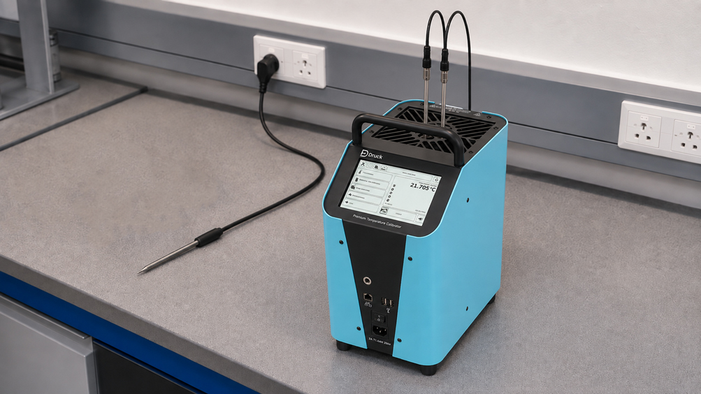
A dry block calibrator can display an almost unchanged temperature for several minutes and still produce different temperatures in two different wells. Likewise, a highly accurate reference probe can measure the actual temperature at its own position very precisely without automatically knowing the exact temperature at the device under test.
This is precisely where incorrect uncertainty estimates often arise in demanding temperature calibrations. Stability, spatial uniformity, reference accuracy and immersion conditions describe different physical effects and must therefore be considered separately.
The temperature shown on the display of a dry block calibrator is therefore not automatically identical to the temperature at the sensitive element of the device under test. Between the two, there may be temporal fluctuations, axial and radial temperature gradients, loading effects and heat conduction along the probe stem.
For a reliable calibration, the question is therefore not only how accurate the dry block calibrator is, but how large the uncertainty of the reference temperature actually acting at the device under test is under the specific calibration setup.
A suitable example for this consideration is the Druck PTC200 Premium Temperature Calibrator offered by ICS Schneider. The dry block covers a temperature range from -55 to 200 °C and can be operated with either an internal or an external reference temperature.
Additional solutions can be found under Calibration Technology at ICS Schneider.
Table of Contents
- Why accuracy and measurement uncertainty are not the same
- What measurement model underlies dry block calibration?
- Display accuracy of the dry block calibrator
- Temperature stability as a time-dependent influence
- Uniformity as a spatial influence
- Axial temperature distribution
- Radial temperature distribution
- Influence of the reference probe
- Distinguishing internal and external reference
- Immersion depth and sensitive length
- Well diameter and thermal contact
- Heat conduction along the probe stem
- Block loading
- Hysteresis and approach direction
- Resolution of calibrator and device under test
- Repeatability of the device under test
- Self-heating of resistance thermometers
- When is a calibration point really stable?
- How to build an uncertainty budget correctly
- From limits to standard uncertainty
- Calculating combined and expanded measurement uncertainty
- Example of an uncertainty budget
- Typical errors in uncertainty evaluation
- Recommended calibration procedure
- Druck PTC200 at ICS Schneider
- Conclusion
- FAQ
Why accuracy and measurement uncertainty are not the same
The data sheet of a dry block calibrator often contains several temperature specifications such as:
- display accuracy,
- stability,
- axial temperature distribution,
- radial temperature distribution,
- loading effect.
These values describe different characteristics of the calibrator.
It would therefore be incorrect to select only one of these values and use it as the:
measurement uncertainty of the temperature calibration
.
The measurement uncertainty of an actual calibration results from several contributions.
In simplified form:
calibrator + reference + temperature distribution + calibration setup + device under test + reading
jointly determine the achievable uncertainty.
An important distinction
A block can, for example, be extremely stable over time and still have a relevant axial temperature gradient.
Likewise, a highly accurate external reference may measure at one position in the block while the sensitive element of the device under test is positioned several centimeters higher.
A small stability specification alone therefore does not prove that the calibration uncertainty is equally small.
What measurement model underlies dry block calibration?
In a comparison calibration, the indication of the device under test is compared with a reference temperature.
In simplified form, the deviation of the device under test can be described as:
ΔT = TDUT − TReference
The difficulty lies in assigning the value:
TReference
to the actual temperature at the device under test with sufficiently low uncertainty.
In addition to the reference measurement, the thermal characteristics of the block must therefore also be taken into account.
A more complete model can, for example, include
ΔT = TDUT − TRef + δTstab + δTax + δTrad + δTload + δTimm + ...
The additional terms can, for example, represent:
- temporal stability,
- axial temperature distribution,
- radial temperature distribution,
- loading effect,
- immersion or heat-conduction effects.
Display accuracy of the dry block calibrator
Display accuracy describes how closely the temperature indicated by the calibrator corresponds to the actual temperature at the reference position defined for this specification.
It should not be confused with:
temperature stability
or:
temperature uniformity
.
For the Druck PTC200
different values are specified depending on the reference used.
For the dry block, Druck specifies:
- with external reference: display accuracy ±0,27 °C,
- with internal reference: display accuracy ±0,34 °C.
Important for high-quality comparison calibrations
however, is that the calibrator display does not necessarily have to be the sole reference quantity.
If a calibrated external reference is positioned directly next to the device under test, the comparison measurement can be based on the actually measured reference temperature.
This results in a different uncertainty model compared with using only the internal calibrator sensor.
Temperature stability as a time-dependent influence
Temperature stability describes how much the temperature at a defined position changes within a specified time window.
It answers the question:
How much does the temperature fluctuate over time?
Example
A calibrator is set to:
100,000 °C
The actual reference temperature changes during the measurement period, for example, between:
99,995 °C and 100,005 °C
This represents a temporal fluctuation range even though the measurement setup has not changed spatially at all.
For the PTC200
Druck specifies for the dry block:
- with external reference: ±0,003 °C stability,
- with internal reference: ±0,020 °C stability.
However
A stability of ±0,003 °C does not mean that two devices under test located at different positions in the insert can also differ from each other by only ±0,003 °C.
This difference is determined by the spatial temperature distribution.
Uniformity as a spatial influence
Uniformity describes temperature differences between different positions in the calibration block.
It therefore answers a different question from stability:
How different is the temperature at different locations?
For dry block calibrators, a distinction is made in particular between
- axial temperature distribution along the well,
- radial temperature distribution between different wells or positions.
Therefore
stability = time-dependent
uniformity = spatial
Both contributions must be considered separately.
Axial temperature distribution
Axial temperature distribution describes the temperature profile along the depth of a well.
The lower area of a calibration insert is normally specifically designed to provide the best temperature uniformity.
For the PTC200
Druck specifies the homogeneous temperature zone as:
the lower 40 mm of the adapter insert
The specified axial temperature distribution is
±0,250 °C
Why is this value important?
Two sensors can have sensitive elements of different lengths.
A short Pt100 may have its temperature-sensitive measuring zone directly at the probe tip, while another sensor has a significantly longer active zone.
Both sensors therefore do not necessarily measure exactly the same average temperature.
It becomes particularly critical
if a device under test cannot be inserted far enough into the specified homogeneous zone.
In this case, the axial temperature gradient can become one of the dominant uncertainty contributions.
Radial temperature distribution
Radial temperature distribution describes differences between various positions or wells in a calibration insert.
For the PTC200
Druck specifies:
±0,070 °C
.
This influence becomes particularly important
when the reference probe and device under test are positioned in separate wells.
Example
The reference is located in the central well while the device under test is located in an outer well.
Even if both sensors:
- are immersed to the same depth,
- are read at the same time,
- are fully stable,
there may still be a temperature difference between the two positions.
Therefore
An external reference does not automatically eliminate radial non-uniformity. It only reduces the reference error at its own position.
Influence of the reference probe
The reference probe itself also has measurement uncertainty.
The uncertainty budget may include, among other things:
- calibration uncertainty of the reference probe,
- calibration uncertainty of the readout instrument,
- long-term drift since the last calibration,
- resolution,
- repeatability,
- self-heating,
- hysteresis,
- thermal conduction along the probe stem.
A common mistake
is to use only the value from the calibration certificate of the reference probe.
However, a calibration certificate initially describes the condition during calibration under the conditions stated there.
For subsequent use, additional contributions may need to be considered.
Distinguishing internal and external reference
A dry block calibrator normally contains an internal temperature sensor for control or indication of the block temperature.
This sensor is located at a defined position in the calibrator by design.
During comparison calibration with an external reference
an additional reference probe is positioned as close as possible to the device under test.
The advantage
is that fluctuations or deviations of the actual local block temperature can be measured directly.
However, the following remain relevant
- spatial differences between reference and device under test,
- different immersion depths,
- different stem diameters,
- heat conduction.
For the PTC200
it is possible to choose between internal and external reference temperature measurement.
For high accuracy requirements, this option is particularly useful because the reference can be positioned closer to the actual measurement location.
Immersion depth and sensitive length
During temperature calibration, the entire probe is not measured uniformly. The position of the temperature-sensitive element is decisive.
Therefore, it must be known
- where the sensitive element is located,
- how long the sensitive zone is,
- how deeply the sensor is actually immersed.
A typical mistake
is to insert two differently designed sensors to the same overall depth.
Their sensitive elements can nevertheless be positioned at different heights.
It is better
to position the measuring zones of the reference and device under test as far as possible:
at the same height within the homogeneous zone
.
Well diameter and thermal contact
The thermal contact between the device under test and calibration insert should be as good as possible.
If the well is significantly larger than the probe diameter, an air gap is created.
Air has comparatively low thermal conductivity
This not only increases the response time.
It can also increase the influence of:
- heat conduction along the probe stem,
- ambient temperature,
- position within the well.
Therefore
an insert well matching the diameter of the device under test should be used.
For precision calibrations
the air gap is not only a question of stabilization time, but can itself become a relevant uncertainty contribution.
Heat conduction along the probe stem
A temperature probe connects the hot or cold measuring zone with the surrounding environment.
Heat can therefore be transported along the metallic probe sheath.
This effect becomes particularly relevant with
- short immersion depth,
- thick metallic probes,
- large temperature differences from ambient,
- short sensitive zones near the block surface.
The result may be
that the sensitive element does not exactly assume the local block temperature.
A simple plausibility check
is to change the immersion depth step by step.
If the measured value does not remain constant with greater immersion depth, this indicates a relevant heat-conduction or immersion effect.
Block loading
A dry block calibrator does not necessarily behave thermally in the same way when only one thin reference probe is inserted compared with several massive devices under test.
Each additional device under test
can:
- remove heat from the block,
- introduce heat into the block,
- redistribute heat spatially.
This effect is referred to as
loading effect or block loading
.
For the PTC200, Druck specifies
for the dry block:
- with external reference: ±0,070 °C loading effect,
- with internal reference: ±0,220 °C loading effect.
For practical use, this means
A characterization performed with only one reference probe does not automatically describe the thermal condition under maximum loading with several devices under test.
Hysteresis and approach direction
The direction from which a calibration point is approached can also have a small influence.
For the PTC200
a hysteresis of:
±0,010 °C
is specified.
Hysteresis means
that slightly different conditions can occur at the same set temperature depending on whether the point was approached:
from a lower temperature
or:
from a higher temperature
.
For high accuracy requirements
upward and downward cycles should therefore be considered or the calibration sequence should be clearly defined.
Resolution of calibrator and device under test
A display with three decimal places does not automatically mean an accuracy of 0,001 °C.
Resolution only describes
the smallest displayable or detectable step.
For the PTC200
the temperature display can be selected between:
0,1 / 0,01 / 0,001 °C
.
However, measurement uncertainty remains
determined by numerous additional contributions.
The device under test also has a resolution
A digital thermometer with:
0,1 °C display resolution
can already contribute significantly to the uncertainty budget due to quantization alone.
Repeatability of the device under test
A device under test does not necessarily indicate exactly the same value when measured repeatedly under identical conditions.
To evaluate repeatability
several measurements can be performed.
A statistical uncertainty contribution can be derived from their scatter.
This is particularly useful for
- high-accuracy digital thermometers,
- temperature switches,
- probes with noticeable signal scatter,
- calibrations with a very small target uncertainty budget.
Self-heating of resistance thermometers
In resistance thermometers, an electrical measuring current flows through the sensing element in order to measure its resistance.
This generates a small amount of power dissipation.
In simplified form
P = I² × R
This power
can slightly heat the sensing element.
The resulting temperature error depends, among other things, on:
- measurement current,
- sensor design,
- heat transfer to the block,
- immersion conditions.
At very small measurement uncertainties
the self-heating of the reference or test probe can therefore also become relevant.
When is a calibration point really stable?
Reaching the setpoint on the display does not automatically mean that the entire calibration setup has reached thermal equilibrium.
After a temperature step, the following must stabilize
- calibration block,
- insert,
- reference probe,
- device under test,
- possibly several additional sensors.
For the PTC200
when using an external reference, stabilization times are specified as:
- from 1 minute to ±0,05 °C,
- from 5 minutes to ±0,005 °C.
These values describe the performance of the calibrator
The specific device under test may require additional time due to its:
- mass,
- design,
- immersion depth,
- thermal coupling.
A robust practical rule is therefore
not only to wait for the set temperature, but also to monitor:
reference signal + DUT signal
for sufficient temporal stability.
How to build an uncertainty budget correctly
An uncertainty budget lists all relevant influence quantities and converts them into comparable standard uncertainties.
For a typical dry block calibration, the following can, for example, be considered
| Influence quantity | Source | Typical meaning |
|---|---|---|
| Calibration of reference | Calibration certificate | Uncertainty of the temperature standard |
| Reference drift | History / specification | Change since last calibration |
| Stability | Dry block calibrator | Temporal temperature fluctuation |
| Axial uniformity | Dry block calibrator / characterization | Temperature difference over immersion depth |
| Radial uniformity | Dry block calibrator / characterization | Temperature difference between wells |
| Loading | Dry block calibrator | Temperature change caused by additional devices under test |
| Hysteresis | Calibrator / device under test | Dependence on approach direction |
| Immersion effect | Calibration setup | Heat conduction along the stem |
| Reference resolution | Readout instrument | Quantization of the reference indication |
| DUT resolution | Device under test | Quantization of the DUT indication |
| Repeatability | Measurement series | Statistical scatter |
Important
Not every theoretically conceivable influence must necessarily make a large contribution.
However, every relevant influence must be:
identified → evaluated → documented
.
From limits to standard uncertainty
The individual specifications cannot simply be added quadratically as ± values.
They must first be converted into standard uncertainties.
Calibration certificate example
A reference probe has an expanded measurement uncertainty of:
U = 0,040 °C at k = 2
The standard uncertainty is then approximately
u = U / k
u = 0,040 / 2 = 0,020 °C
Rectangular distribution
If an influence is only specified with a maximum limit of:
±a
and a rectangular distribution is considered appropriate, then:
u = a / √3
Example
An influence is assumed to be:
±0,030 °C
.
This gives:
u = 0,030 / √3 ≈ 0,0173 °C
The decisive point is
The probability distribution used must match the origin and meaning of the respective specification. A data-sheet limit, a standard deviation from repeated measurements and an expanded uncertainty from a calibration certificate must not be treated identically.
Calculating combined and expanded measurement uncertainty
Once the relevant uncertainty contributions have been determined as standard uncertainties and are sufficiently independent, they are typically combined using the root-sum-of-squares method.
In simplified form
uc = √(u1² + u2² + u3² + ...)
The expanded measurement uncertainty
is then often stated as:
U = k × uc
At
k = 2
under suitable conditions, this gives an approximate coverage interval of about 95 %.
Important
This calculation assumes that the underlying measurement model and the contributions used have been selected correctly from a technical perspective.
A mathematically correct calculation cannot compensate for an incomplete measurement model.
Example of an uncertainty budget
The following example is intended solely to illustrate the methodology. The values do not represent a complete uncertainty budget for the PTC200 and are not a generally applicable calibration uncertainty.
| Influence | Specification | Assumption | Standard uncertainty |
|---|---|---|---|
| Reference calibration | U = 0,040 °C, k = 2 | Calibration certificate | 0,0200 °C |
| Reference drift | ±0,020 °C | rectangular | 0,0115 °C |
| Temperature stability | ±0,020 °C | rectangular | 0,0115 °C |
| Radial uniformity | ±0,050 °C | rectangular | 0,0289 °C |
| Axial uniformity | ±0,080 °C | rectangular | 0,0462 °C |
| Loading effect | ±0,030 °C | rectangular | 0,0173 °C |
| DUT resolution | 0,01 °C | ±0,005 °C rectangular | 0,0029 °C |
| Repeatability | s = 0,015 °C | statistically determined | 0,0150 °C |
Root-sum-of-squares combination
gives approximately:
uc ≈ 0,065 °C
With k = 2
this results, for example, in:
U ≈ 0,13 °C
It is particularly revealing
that in this example it is not stability but:
axial uniformity
that provides the largest individual contribution.
This is exactly why
the achievable calibration uncertainty must not be derived solely from the smallest number in the data sheet.
Typical errors in uncertainty evaluation
| Observation / approach | Problem | Recommended correction |
|---|---|---|
| Only stability is used as uncertainty | Spatial temperature distribution is missing | Consider axial and radial uniformity separately |
| Calibrator displays 0,001 °C resolution | Resolution is confused with accuracy | Consider the complete uncertainty budget |
| External reference is used, uniformity is ignored | Reference and DUT are not at the same position | Consider the positional difference |
| Several DUTs are inserted simultaneously | Block loading changes the thermal condition | Consider the loading effect |
| DUT does not reach the homogeneous zone | Axial gradient can dominate | Change immersion depth or determine the influence |
| Large air gap between probe and insert | Poor thermal contact | Use a suitable calibration insert |
| Reference and DUT have different sensitive lengths | Different temperature regions are averaged | Compare the positions of the sensitive elements |
| Measured value is recorded immediately after reaching the setpoint | DUT may not yet have stabilized | Monitor reference and DUT for stability |
| All ± limits are directly added quadratically | No conversion to standard uncertainties | Use the correct distribution and divisor |
| U from the calibration certificate is directly combined with standard uncertainties | Expanded and standard uncertainties are mixed | First divide U by the specified k factor |
| DUT is read only once | Repeatability remains unknown | Perform a measurement series if required |
| Temperature is approached only in the upward direction | Hysteresis remains undetected | If required, check both upward and downward cycles |
Recommended calibration procedure
- Define calibration requirements: Determine temperature points, required uncertainty and permissible deviation.
- Select the calibrator: Check the temperature range and required thermal characteristics.
- Define the reference strategy: Decide whether an internal or external reference will be used.
- Check the calibration status of the reference: Verify calibration certificate, uncertainty and validity.
- Identify the device under test: Determine probe type, diameter, sensitive length and required immersion depth.
- Select a suitable insert: Match the well diameter as closely as possible to the probe diameter.
- Position reference and device under test: Arrange the sensitive elements as far as possible at the same height within the homogeneous zone.
- Consider loading: When several devices under test are inserted, take their influence on the block into account.
- Approach the set temperature: Bring the calibrator to the required point in a controlled manner.
- Wait for thermal stabilization: Monitor not only the calibrator display but also the reference and device under test.
- Record measured values simultaneously: Record reference and DUT values as closely as possible at the same time.
- Perform repeated measurements: Determine repeatability if required.
- Check additional temperature points: Cover the calibration range according to the measurement task.
- Perform a downward cycle if necessary: Evaluate hysteresis.
- Calculate measurement deviation: Evaluate the device under test against the reference.
- Determine uncertainty contributions: Consider reference, stability, uniformity, loading, immersion, resolution and repeatability.
- Convert contributions to standard uncertainty: Correctly handle expanded uncertainties, limits and statistical contributions.
- Calculate combined uncertainty: Combine relevant independent contributions using the root-sum-of-squares method.
- State expanded uncertainty: Document the appropriate coverage factor and its meaning.
- Document the calibration setup: Record insert, well, immersion depth, reference position, DUT position and loading.
Druck PTC200 Premium Temperature Calibrator at ICS Schneider
For precise dry block calibrations, ICS Schneider offers the:
Druck PTC200 Premium Temperature Calibrator
as a dedicated product.
For the PTC200, ICS and Druck specify, among other things
- temperature range -55 to 200 °C at 20 °C ambient temperature,
- dry block design,
- calibration insert Ø 28 × 150 mm,
- replaceable calibration insert,
- internal or external reference temperature measurement,
- selectable display resolution 0,1 / 0,01 / 0,001 °C,
- touchscreen operation,
- fast heating and cooling times through combined heating and Peltier technology.
Particularly relevant to the uncertainty budget
are the separately specified thermal characteristics.
| PTC200 characteristic | External reference | Internal reference |
|---|---|---|
| Display accuracy | ±0,27 °C | ±0,34 °C |
| Temperature stability | ±0,003 °C | ±0,020 °C |
| Loading effect | ±0,070 °C | ±0,220 °C |
In addition, Druck specifies the following temperature distribution values
- axial: ±0,250 °C,
- radial: ±0,070 °C.
The homogeneous temperature zone
for the PTC200 is specified as:
the lower 40 mm of the adapter insert
.
These specifications clearly demonstrate
why stability, uniformity and reference must not be combined into a single characteristic value.
The:
±0,003 °C stability
with an external reference, for example, describes a completely different influence from the:
±0,250 °C axial temperature distribution
For a high-quality calibration
it is therefore essential not only to use the PTC200 within its temperature range, but to consider the complete:
calibrator + insert + reference + DUT + positioning
as one measurement system.
Conclusion
In a temperature calibration using a dry block calibrator, no single data-sheet specification determines the achievable measurement uncertainty. The actual uncertainty results from the interaction between the reference measurement, thermal characteristics of the block and the specific device under test.
Stability and uniformity describe different effects
Stability evaluates temperature change over time.
Uniformity evaluates temperature differences in space.
Axial and radial uniformity should also be considered separately
Different immersion depths and different well positions create different uncertainty contributions.
An external reference improves knowledge of the local temperature
However, it does not automatically eliminate temperature differences between its own position and the device under test.
Immersion depth can become the dominant influence
Especially with short probes or large temperature differences from ambient, heat conduction along the stem can cause significant deviations.
Loading is also part of the measurement model
Several devices under test inserted simultaneously can change the temperature distribution of the block.
Resolution is not accuracy
A display with 0,001 °C resolution alone says nothing about measurement uncertainty in the millikelvin range.
For calculation, all contributions must first be made comparable
Expanded uncertainties from calibration certificates, data-sheet limits and statistical standard deviations must not be combined without conversion.
The Druck PTC200 illustrates the separation of these influences particularly well
because stability, axial and radial temperature distribution, loading effect and internal or external reference are specified separately.
For practical applications
Define the calibration requirements → select the reference and device under test → use a suitable insert → position the sensitive elements at the same height within the homogeneous zone → ensure sufficient immersion depth → consider loading → approach the temperature point → allow the reference and device under test to fully stabilize → measure simultaneously → perform repeated measurements and upward/downward cycles where required → evaluate reference uncertainty, drift, stability, axial and radial uniformity, loading effect, immersion effect, resolution and repeatability separately → convert all contributions into standard uncertainties → calculate combined uncertainty → state expanded measurement uncertainty → document the entire calibration setup.
FAQ: Measurement Uncertainty with Dry Block Calibrators
What determines the measurement uncertainty of a dry block calibrator?
Among other things, the reference measurement, temporal stability, axial and radial temperature distribution, loading, immersion depth, thermal contact, resolution and characteristics of the device under test.
Is the accuracy specification of the dry block calibrator the same as the calibration uncertainty?
No. The instrument’s accuracy specification is only one part of the overall evaluation.
What does temperature stability mean?
It describes how much the temperature at a defined position changes within a specified period of time.
What does temperature uniformity mean?
It describes temperature differences between different spatial positions in the calibration block.
What is the difference between axial and radial uniformity?
Axial uniformity concerns temperature differences along the depth of a well. Radial uniformity concerns differences between different positions or wells in the block.
Can a block be very stable and still be relatively non-uniform?
Yes. The temperature at each position can remain almost constant over time while still being different between two positions.
Why is immersion depth so important?
If the immersion depth is insufficient, heat can be conducted along the probe stem to the surrounding environment. In addition, the sensitive element may be located outside the specified homogeneous zone.
Do the reference and DUT have to be immersed to the same depth?
The most important factor is that their sensitive regions are positioned as far as possible at the same height within the homogeneous measuring zone.
Why is an external reference alone not sufficient?
An external reference only measures the temperature at its own position. Spatial temperature differences may still exist between the reference and the DUT.
What is block loading?
Block loading describes the change in the thermal condition of the calibrator caused by inserted sensors and their heat conduction.
Why can several devices under test increase measurement uncertainty?
Additional devices under test change the thermal load and can therefore influence temperature distribution and control behavior.
Why should the well match the probe diameter as closely as possible?
A small air gap improves thermal contact and reduces response time as well as influences caused by heat conduction.
Does a display resolution of 0,001 °C mean an accuracy of 0,001 °C?
No. Resolution only describes the smallest displayable change. The actual measurement uncertainty can be significantly larger.
What is reference uncertainty?
It describes the uncertainty with which the reference temperature is known. This particularly includes calibration of the reference system and, where applicable, additional influences such as drift.
How is expanded measurement uncertainty from a calibration certificate used?
If, for example, U is specified with k = 2, the standard uncertainty u = U / 2 is first used for the uncertainty budget.
How is a ± limit converted into standard uncertainty?
For an assumed rectangular distribution and a symmetrical limit ±a, u = a / √3 typically applies.
How are independent uncertainty contributions combined?
Typically using the root-sum-of-squares method with uc = √(u1² + u2² + ...).
What does k = 2 mean?
The coverage factor k = 2 is frequently used to determine expanded uncertainty from combined standard uncertainty. Under suitable conditions, this approximately corresponds to a coverage interval of about 95 %.
Must the repeatability of the device under test be taken into account?
For demanding calibrations, yes, provided the observed scatter makes a relevant contribution to the total uncertainty.
Can a resistance thermometer heat itself?
Yes. The measurement current generates electrical power dissipation in the resistance element and can produce a measurable self-heating effect when high accuracy is required.
When may a measured value be recorded after a temperature change?
Only when not only the block, but also the reference and device under test have sufficiently stabilized thermally.
What is the homogeneous zone of a dry block calibrator?
It is the area of the calibration insert for which the temperature distribution has been characterized or specified.
How large is the homogeneous zone of the Druck PTC200?
Druck specifies the lower 40 mm of the adapter insert as the homogeneous temperature zone.
What temperature range does the Druck PTC200 have?
ICS and Druck specify -55 to 200 °C at an ambient temperature of 20 °C.
What are the dimensions of the PTC200 calibration insert?
The replaceable calibration insert has dimensions of Ø 28 × 150 mm.
What temperature stability does the PTC200 provide?
Druck specifies ±0,003 °C with an external reference and ±0,020 °C with an internal reference in dry block operation.
What axial temperature distribution does Druck specify for the PTC200?
An axial temperature distribution of ±0,250 °C is specified for the dry block.
What radial temperature distribution does Druck specify?
A radial temperature distribution of ±0,070 °C is specified for the PTC200.
What loading effect does the PTC200 have?
Druck specifies ±0,070 °C with an external reference and ±0,220 °C with an internal reference.
What display resolution does the PTC200 provide?
The temperature display can be set to 0,1, 0,01 or 0,001 °C.
Can the PTC200 use an external reference?
Yes. The instrument supports both internal and external reference temperature measurement.
Why is an external reference useful for demanding calibrations?
It enables direct measurement of the temperature closer to the device under test and can therefore improve knowledge of the reference temperature actually acting at the measurement point.
Where can I find the Druck PTC200 at ICS Schneider?
Further information can be found under Druck PTC200 Premium Temperature Calibrator at ICS Schneider.
Where can I find additional calibration technology at ICS Schneider?
An overview can be found under Calibration Technology at ICS Schneider.