


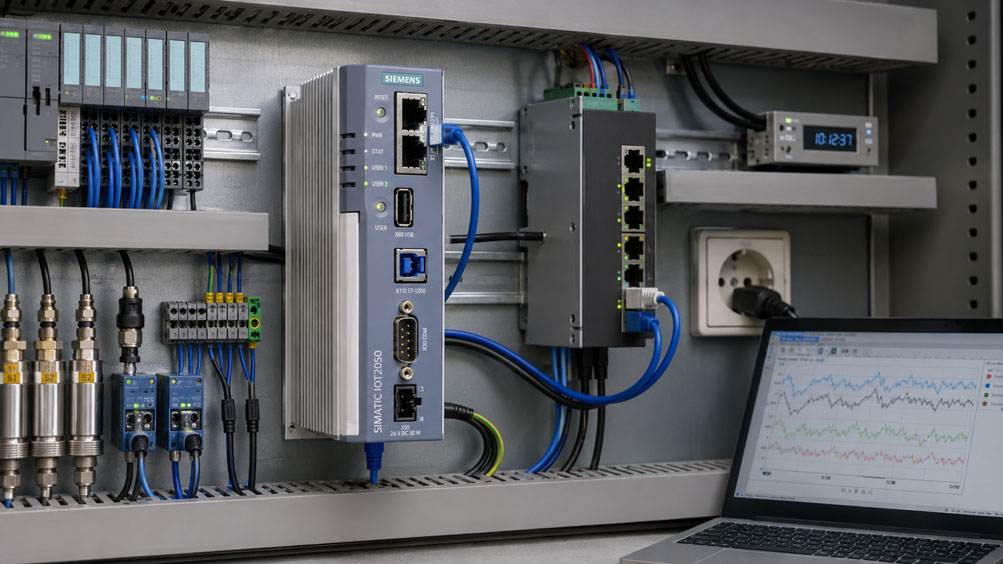
A measured value without a reliable time reference is often of only limited use in an IIoT application. This becomes particularly apparent in the case of faults, short process events or subsequent root-cause analysis: Two systems report a pressure change, a motor vibration alarm and a machine shutdown almost simultaneously – but which event actually occurred first?
The accuracy of the clock is not the only decisive factor. It is equally important at which point in the data chain the timestamp is generated.
If a measured value is timestamped directly in the sensor or immediately when it is acquired, its original measurement time is retained even if the data is transmitted later. If, on the other hand, the timestamp is only generated at the gateway or even in the cloud, it initially only indicates when the value arrived there.
The greater and more variable the communication latency between measurement and timestamp generation, the more difficult it becomes to reliably reconstruct the actual event time later.
For typical IIoT architectures, ICS Schneider offers solutions ranging from field devices and edge gateways to IT and cloud connectivity. Further information can be found under IIoT solutions at ICS Schneider.
A practical example of a sensor-gateway architecture is the Siemens SITRANS MS200 IIoT multisensor, which ICS offers for vibration and temperature monitoring in combination with the SITRANS CC220 gateway. For digitizing weighing signals, the Siemens IIoT weighing electronics 7MH4647-0KK00-0AA2 is also available for applications with the SIMATIC IOT2050.
Table of Contents
- Why is the timestamp so important for IIoT measurement data?
- Which timestamps exist in a measurement data chain?
- Generating the timestamp directly in the sensor
- Generating the timestamp in the PLC
- Generating the timestamp at the gateway
- Why the cloud reception time is usually not sufficient
- Sensor, PLC or gateway: Which option is better?
- Understanding transmission latency and jitter
- What happens during buffering and connection interruptions?
- Why timestamps alone do not always preserve event order
- Adding sequence numbers and event IDs
- SourceTimestamp and ServerTimestamp in OPC UA
- Timestamps and message order in MQTT
- NTP for time synchronization
- When PTP is useful
- Handling UTC, time zones and daylight saving time correctly
- Detecting clock drift and time jumps
- Distinguishing sampling rate from timestamp resolution
- Which time information should be stored?
- Practical example: fault analysis on a machine
- Practical example: gateway offline for 30 seconds
- Integrating brownfield systems without timestamps
- Typical fault patterns
- Recommended planning and commissioning procedure
- Suitable IIoT solutions from ICS Schneider
- Conclusion
- FAQ
Why is the timestamp so important for IIoT measurement data?
In many simple applications, it is initially sufficient to display a current measured value on a dashboard.
However, as soon as the data is to be used for:
- fault analysis,
- condition monitoring,
- quality assurance,
- batch traceability,
- energy analysis,
- predictive maintenance,
- alarm correlation
the actual measurement time becomes crucial.
Example
A machine reports within a few seconds:
- increasing motor vibration,
- pressure drop,
- speed decrease,
- emergency stop or machine shutdown.
For root-cause analysis, it must be known:
Which event occurred first?
If all data is only assigned the time at which it was stored in the cloud, the original sequence may already have been distorted by different transmission times.
Which timestamps exist in a measurement data chain?
A single measured value can pass through several different timestamps during transmission.
| Timestamp | Meaning |
|---|---|
| Measurement time | Time at which the physical value was actually acquired |
| Sensor timestamp | Time assigned to the measured value by the field device |
| PLC acquisition time | Time at which the controller receives the value |
| Gateway time | Time at which the edge gateway receives or reads the value |
| Publish time | Time at which a message is transmitted, for example via MQTT |
| Broker/server time | Time at which the value is accepted by a higher-level system |
| Storage time | Time at which the data record is stored in a historian, database or cloud |
With a fast local Ethernet connection, these times may differ by only a few milliseconds.
With:
- wireless connections,
- cellular communication,
- LoRaWAN,
- cyclic Modbus polling,
- gateway buffering,
- network faults
the difference can be significantly larger and, above all, more variable.
Generating the timestamp directly in the sensor
From a timing perspective, the cleanest solution is generally to generate the timestamp as close as possible to the actual measurement acquisition.
Advantage
The timestamp then actually represents the time of the measurement or event.
Subsequent:
- communication latency,
- queues,
- gateway processing,
- cloud transmission
no longer alter this original time reference.
Requirement
The sensor requires:
- its own clock or suitable time base,
- a synchronization option or sufficiently stable clock,
- a protocol that can transmit the timestamp together with the measured value.
A sensor timestamp is not automatically better
If a field device has a real-time clock but it is not correctly synchronized, the timestamp can be systematically incorrect.
In practice, a gateway with a properly synchronized clock may then be more reliable than a supposedly precise but drifting sensor timestamp.
The best position for generating the timestamp is as close as possible to the data source – but only if the time base used there is reliable.
Generating the timestamp in the PLC
In many machines, the actual process is already acquired by a PLC.
The controller can therefore be a suitable point for timestamp generation.
This is particularly suitable when
- multiple signals converge in the same PLC,
- digital events are to be correlated with each other,
- the PLC clock is centrally synchronized,
- the sensor itself does not provide a timestamp.
However, it must be considered that
the PLC timestamp does not necessarily represent the physical measurement time either.
Between:
Sensor acquisition
and:
PLC processing
the following delays may already occur:
- sensor filtering time,
- bus cycle,
- I/O update time,
- PLC cycle time.
For normal machine monitoring, this difference may be insignificant.
For very fast events, however, the entire timing chain of the signal must be considered.
Generating the timestamp at the gateway
Especially in brownfield installations, many existing field devices do not have their own timestamp function at all.
An edge gateway can then assign a time value when reading the measured value.
A typical architecture is:
Sensor → Fieldbus → Edge gateway → MQTT/HTTPS/OPC UA → IT/Cloud
Advantages
- central time base for many field devices,
- NTP synchronization comparatively easy to implement,
- uniform data model,
- brownfield sensors without a real-time clock can be used,
- local buffering with timestamps is possible.
The key disadvantage
The gateway timestamp initially represents:
Time of reading or reception
and not necessarily:
Time of the actual measurement
With cyclic polling
a gateway may, for example, query:
- Sensor A,
- Sensor B,
- Sensor C,
- Sensor D
one after another.
The four values may have been generated physically almost simultaneously but receive different gateway timestamps because of the polling sequence.
Conversely, a sensor may provide an internally older value that is only queried later.
For gateway timestamps, it must therefore be documented whether the time value represents measurement time, polling time or reception time.
Why the cloud reception time is usually not sufficient
The latest possible point for timestamp generation is the higher-level IT or cloud system.
This may be sufficient for simple status displays.
For technical event analysis, however, it is often problematic.
Between measurement and cloud there may be
- sensor cycle,
- fieldbus transmission,
- gateway processing,
- local data buffer,
- broker,
- WAN or cellular connection,
- cloud ingestion,
- database queue.
A delay at only one of these points changes the cloud reception time.
The physical measurement time, however, remains unchanged.
Sensor, PLC or gateway: Which option is better?
| Timestamp generated at | Advantage | Considerations |
|---|---|---|
| Sensor | very close to the actual measurement time | sensor clock must be synchronized and reliable |
| PLC | good correlation of many machine signals | I/O, bus and PLC cycles already occur before the timestamp |
| Gateway | ideal for brownfield systems and a uniform time base | timestamp often corresponds to reception or polling |
| Cloud/server | technically simple | network and buffering latency distort the event time |
Rule of thumb
Generate the timestamp as close as reasonably possible to the origin of the measured value and then preserve it unchanged throughout the entire data chain.
Understanding transmission latency and jitter
Latency describes the delay between two points in the data chain.
If a value is acquired at the sensor at:
tsource
and received at the gateway at:
tgateway
the following can be considered in simplified form:
Δt = tgateway − tsource
However, this observed difference does not consist solely of communication latency.
It may include
- sensor processing time,
- bus waiting time,
- transmission time,
- gateway processing,
- difference between the two clocks.
Only if the clocks are sufficiently synchronized can the difference between the timestamps be used meaningfully to infer actual latency.
Jitter
describes the variation in this delay over time.
For example:
10 ms → 11 ms → 37 ms → 9 ms
A constant latency can often be taken into account.
Strong jitter is much more problematic for subsequent event sorting.
What happens during buffering and connection interruptions?
A good edge system should be able to store measured values locally when a connection is interrupted.
The data is transmitted later as soon as:
- network,
- broker,
- server
are available again.
This is where the advantage of a source timestamp becomes particularly clear
Assume a measured value is generated at:
10:15:01
.
However, the gateway does not regain its connection to the cloud until:
10:15:31
.
With the original timestamp
the data record is still stored as:
Measurement time = 10:15:01
With cloud reception time only
it would instead appear as:
Time = 10:15:31
and would therefore be shifted by 30 seconds.
With many buffered values
the problem can become even more severe.
Thirty measured values from 30 seconds may be transmitted to the cloud within only a few hundred milliseconds.
If they were timestamped only there, it would appear as if all values had been generated almost simultaneously.
Store-and-forward systems should therefore buffer the original acquisition time together with the measured value.
Why timestamps alone do not always preserve event order
Even correctly synchronized timestamps do not solve every problem.
Two events can receive the same timestamp
For example, if:
- the time resolution is only 1 ms,
- multiple events occur within the same millisecond.
In addition
- packets may be delayed,
- messages may be retransmitted,
- data from multiple sources may converge,
- clocks may differ slightly.
For reliable event reconstruction, sorting should therefore not rely exclusively on a timestamp.
Adding sequence numbers and event IDs
A robust telemetry message can include additional metadata in addition to the measured value.
For example:
value = 7.42
sourceTimestamp = 2026-08-25T10:15:01.125Z
sequence = 583214
quality = good
deviceId = pressure_017
A sequence number helps with
- detecting lost data records,
- detecting duplicates,
- reconstructing the order within a source,
- verification after an offline phase.
A unique event ID
can additionally prevent the same message from being stored or evaluated multiple times after retransmission.
Timestamps and sequence numbers serve different purposes and therefore complement each other effectively.
SourceTimestamp and ServerTimestamp in OPC UA
OPC UA explicitly distinguishes between different time information for a data value.
SourceTimestamp
The SourceTimestamp describes the timestamp assigned to the value by its data source.
It should be generated as close as possible to the source of the measured value.
ServerTimestamp
The ServerTimestamp, on the other hand, describes the time at which the OPC UA server received the value or knew that this value was valid.
This is particularly useful for IIoT architectures
A value can, for example, have:
SourceTimestamp = 10:15:01.125
and:
ServerTimestamp = 10:15:01.142
.
This keeps:
- the original data time,
- the server processing time
distinguishable from each other.
If an OPC UA value is forwarded
the original SourceTimestamp should not be replaced by a later gateway timestamp.
Additional time information can be added separately.
Timestamps and message order in MQTT
MQTT is very well suited for transmitting telemetry data between edge and IT systems.
The actual application-specific timestamp of the measured value should be included in the data model or payload if it is required by the application.
Example
{"value":7.42,"timestamp":"2026-08-25T10:15:01.125Z","seq":583214}
MQTT has rules for message ordering
For ordered topics, messages from a publisher are forwarded in publishing order under the corresponding conditions.
However, this does not mean that the MQTT broker knows the actual physical measurement time.
In addition, retransmissions can
for example with QoS 1 after a connection interruption, result in duplicate messages.
Applications for which an unambiguous historical sequence is important should therefore additionally use:
- Source Timestamp,
- sequence number,
- event ID where appropriate
.
NTP for time synchronization
NTP – Network Time Protocol – is a widely used method for synchronizing system clocks over IP networks.
For many typical IIoT applications, NTP is a suitable solution.
Typical applications include
- trend recording,
- energy monitoring,
- condition monitoring,
- production data,
- normal alarm correlation.
A common time source is important
Ideally:
- PLCs,
- gateways,
- servers,
- relevant sensors
synchronize to a controlled time reference.
Do not only configure the time
It should also be monitored whether synchronization is actually working.
A gateway may, for example, remain technically accessible and continue transmitting data even though its NTP service has failed.
The measured values would still be complete, but their temporal assignment could increasingly drift.
When PTP is useful
PTP – Precision Time Protocol – is used when significantly tighter time synchronization between devices is required.
This may be relevant for
- very fast machine events,
- high-resolution condition monitoring,
- electrical events,
- distributed measurement systems,
- applications where the order within very small time windows is critical.
PTP is not merely a software setting
The achievable synchronization quality depends, among other things, on:
- device support,
- network hardware,
- timestamping method,
- network topology,
- PTP profile or configuration.
A system should therefore not be described as highly precise and time-synchronized merely because PTP has been enabled somewhere in the network.
| Requirement | Typical approach |
|---|---|
| normal IIoT monitoring | NTP often sufficient |
| historical trends over seconds/minutes | NTP |
| close event correlation across many devices | check NTP quality, use PTP if necessary |
| very fast distributed measurements | evaluate PTP or system-specific synchronization |
Handling UTC, time zones and daylight saving time correctly
For internal storage of measurement data, UTC is generally the most robust time base.
Problem with local time
When switching from daylight saving time to standard time, for example, the same local time can occur twice.
An event at:
02:30
may therefore not be unambiguous without additional information.
Recommendation
Store internally:
UTC
and apply the local time zone only in:
- dashboards,
- reports,
- user interfaces
.
A suitable format is, for example
2026-08-25T10:15:01.125Z
The suffix:
Z
indicates UTC.
Detecting clock drift and time jumps
No real clock runs perfectly indefinitely.
Without synchronization, clock drift occurs.
Example
Gateway A runs:
+1.5 s
fast per day.
Gateway B runs:
−0.8 s
slow per day.
After only a few days, events may already be sorted incorrectly in time.
Corrections themselves can also be problematic
If a system clock is suddenly moved forward or backward, sorting purely by local clock time can result in:
- time jumps,
- duplicate time values,
- events apparently running backward in time
.
For local duration measurements
an additional monotonic system counter is therefore often useful.
For correlation between different devices, however, a common UTC-based time reference remains necessary.
Distinguishing sampling rate from timestamp resolution
A large number of decimal places in a timestamp does not automatically mean that the measured value was actually acquired with this time accuracy.
Example
A sensor updates its measured value only every:
1 s
.
However, the gateway assigns the queried value a timestamp with:
1 µs resolution
.
This merely represents the reception time at high resolution.
The actual measurement time is not suddenly known to microsecond accuracy.
The following must therefore be distinguished
- sensor sampling rate,
- signal filtering,
- communication cycle,
- timestamp resolution,
- synchronization accuracy.
Timestamp resolution and actual time accuracy are not the same thing.
Which time information should be stored?
For more demanding IIoT projects, it is useful to store more than just a single time value.
| Data field | Purpose |
|---|---|
| value | actual measured quantity |
| sourceTimestampUtc | original measurement or event time |
| gatewayTimestampUtc | reception or processing at the edge |
| sequenceNumber | order within the source |
| quality | validity or measured-value status |
| deviceId | unique data source |
| bootId or sessionId | identification of a device restart or new data cycle |
Optionally, the following can also be stored
- cloud reception time,
- broker time,
- synchronization status of the source,
- estimated time uncertainty.
This makes it much easier to determine later whether a timing deviation originated from the process or from data transmission.
Practical example: fault analysis on a machine
A production machine has three separate measuring systems:
- vibration sensor,
- pressure sensor,
- PLC with motor speed.
At:
14:22:17
the machine stops unexpectedly.
Cloud reception times
The historian shows:
14:22:17.430 – pressure drop
14:22:17.440 – strong vibration
14:22:17.455 – speed decrease
Based on this, the pressure drop would initially be suspected as the cause.
Source Timestamps
However, the original timestamps show:
14:22:17.310 – strong vibration
14:22:17.365 – speed decrease
14:22:17.390 – pressure drop
Cause of the incorrect order
The vibration data was transmitted over a communication path with higher latency.
The pressure value therefore reached the higher-level system first even though the physical event occurred later.
For root-cause analysis, the Source Timestamp is decisive, not the order in which messages arrive in the central system.
Practical example: gateway offline for 30 seconds
An edge gateway acquires one measured value every:
1 s
.
The connection to the MQTT broker fails for:
30 s
.
Correct implementation
The gateway stores for each value:
- measured value,
- original timestamp,
- sequence number.
Once the connection is restored, all 30 data records are transmitted.
The time series remains correct.
Problematic implementation
The gateway stores only the measured values.
When the data is later transmitted, a new timestamp is generated for each value.
The entire offline period then appears as a short block of measured values at the time of reconnection.
Correct trend analysis would no longer be possible.
Integrating brownfield systems without timestamps
Many existing machines have:
- 4–20 mA sensors,
- Modbus RTU devices,
- older PLCs,
- simple counters
without their own timestamp function.
An edge gateway is often the most practical solution here
It can:
- poll devices cyclically,
- scale values,
- assign a gateway timestamp,
- buffer data locally,
- convert it into a uniform data model,
- forward it via MQTT or HTTPS.
Correct semantics are important
A gateway timestamp should then not be described as:
exact sensor measurement time
.
A correct description would be, for example:
Acquisition time at gateway
or:
Polling Timestamp
.
This clear distinction prevents incorrect interpretation of data quality later.
Typical fault patterns
| Observation | Possible cause | Recommended check |
|---|---|---|
| Events appear in the wrong order | different communication latencies | compare Source Timestamp instead of reception time |
| Measured values appear simultaneously after a network failure | timestamp generated only during retransmission | check store-and-forward configuration |
| Two gateways drift apart in time | NTP missing or not working | check time synchronization status |
| Measurement data jumps backward in time | system clock was corrected | check NTP log and clock behavior |
| Daylight saving time produces duplicate times | local time stored | use UTC internally |
| Gateway timestamps systematically differ between sensors | serial polling | check polling cycle and register structure |
| Very precise timestamp but poor event correlation | time resolution confused with actual accuracy | check sensor sampling rate and synchronization |
| Some data points are missing after an offline period | buffer overflow or packet loss | evaluate sequence numbers |
| Duplicate data records after MQTT reconnect | message retransmitted | evaluate sequence number or event ID |
| Source Timestamp is older than gateway time by strongly varying amounts | jitter or variable buffering | calculate latency statistics |
| Sensor and PLC disagree on event sequence | different time sources | check synchronization architecture |
| Gateway shows correct time but historian time is incorrect | time-zone or UTC conversion | check the entire data chain |
| Timestamps are missing only for individual field devices | source protocol does not provide time information | identify gateway acquisition time separately |
Recommended planning and commissioning procedure
- Define the measurement task: Determine whether trends, alarms or exact event sequences are required.
- Determine the required time accuracy: Define seconds, milliseconds or smaller.
- Determine sampling rates: Know sensor and PLC update times.
- Inventory data sources: Record sensors, PLCs, gateways and servers.
- Check timestamp capability: Determine which devices provide a Source Timestamp.
- Define the timestamp source: Deliberately select sensor, PLC or gateway.
- Define semantics: Clearly distinguish measurement time, reception time and storage time.
- Define the time source: Plan a central NTP approach or PTP if required.
- Define the time-zone strategy: Preferably use UTC internally.
- Monitor synchronization status: Make failures of the time source detectable.
- Analyze gateway polling: Take polling cycles and the resulting time uncertainty into account.
- Define buffering: Specify behavior during network failure.
- Preserve the original timestamp: Do not overwrite it when forwarding data.
- Provide a sequence number: Make missing and duplicate measured values detectable.
- Transfer quality status: Mark invalid or uncertain values.
- Check OPC UA time fields: Use SourceTimestamp and ServerTimestamp correctly.
- Define the MQTT data model: Include timestamp and sequence number in the payload or data model.
- Perform an offline test: Deliberately interrupt the network and check retransmission.
- Perform a clock-drift test: Compare timing deviations between several devices.
- Test event order: Trigger defined events at multiple sources.
- Check the historian: Ensure Source Time and Ingestion Time are not confused.
- Create documentation: Record timestamp source and time accuracy for each measured quantity.
Suitable IIoT solutions from ICS Schneider
IIoT solutions – from field device to cloud
Under IIoT solutions at ICS Schneider, cross-manufacturer architectures for connecting sensors, controllers and field devices to edge, SCADA and cloud systems are brought together.
Typical interfaces and protocols include:
- RS-485 / Modbus RTU,
- HART,
- IO-Link,
- OPC UA,
- Ethernet,
- MQTT,
- HTTPS.
A typical IIoT chain is:
Field device → Edge gateway → MQTT/HTTPS → SCADA/Cloud/BI
Siemens SIMATIC IOT2050 – edge gateway platform
The SIMATIC IOT2050 is an industrial gateway platform for acquiring, processing, harmonizing, locally storing and forwarding machine and production data.
The platform is therefore particularly suitable for brownfield architectures in which existing:
- field devices,
- controllers,
- serial interfaces,
- Ethernet data sources
are to be integrated into a higher-level IIoT data structure.
The specific functions available for:
- timestamping,
- NTP or PTP,
- OPC UA,
- MQTT,
- local buffering
depend on the hardware, operating-system and software configuration used and should be evaluated for the specific project.
Siemens SITRANS MS200 – IIoT multisensor
The Siemens SITRANS MS200 is a wireless IIoT sensor for:
- vibration,
- temperature.
ICS describes the device for operation in combination with the SITRANS CC220 gateway.
The architecture:
SITRANS MS200 → SITRANS CC220 → higher-level monitoring
is a good example of why an IIoT solution must clearly define at which point measured values receive their authoritative timestamp.
Siemens IIoT weighing electronics for SIMATIC IOT2050
The IIoT weighing electronics 7MH4647-0KK00-0AA2 are designed for connecting a load cell or strain-gauge full bridge with:
1 … 4 mV/V
and are intended for use with the SIMATIC IOT2050.
A corresponding architecture can, for example, be:
Load cell → Weighing electronics → SIMATIC IOT2050 → higher-level system
With such a data chain, it should also be defined whether the timestamp is generated:
- during the actual measurement acquisition,
- during digital processing,
- at the gateway
.
Conclusion
For reliable IIoT time series, it is not sufficient to assign just any time value to each measured value.
The Source Timestamp is the most important time reference
For event analysis, the time of the actual measurement or the earliest possible acquisition should be retained.
The timestamp should be generated as close as possible to the source
The sensor or PLC is particularly suitable if a reliable and synchronized time base is available there.
Gateway timestamping is very useful for brownfield systems
It also enables consistent timing for older sensors. However, the value often describes the reception or polling time.
Cloud time is not measurement time
Network latency, buffering and retransmissions can move the reception time significantly away from the actual event time.
Original timestamps must be preserved during buffering
Otherwise, the actual time intervals between measured values are lost during an offline period.
Timestamps alone are not always sufficient
Sequence numbers, event IDs and quality information help detect duplicates, packet loss and ordering problems.
NTP or PTP must match the application
NTP is sufficient for many conventional IIoT applications. For very tight event correlation, a more precise synchronization architecture such as PTP may need to be evaluated for the specific project.
UTC simplifies data management
Time zones and daylight saving time should preferably only be taken into account when the data is displayed.
For practical applications
Define measurement requirements → determine the actual measurement time → check the timestamp capability of the data source → generate the timestamp as close as possible to the source → establish a common time reference → use UTC → preserve the original timestamp when forwarding data → store gateway and reception time separately → add sequence number and quality status → test offline buffering → monitor clock drift → practically verify event order → document the time architecture.
FAQ: Timestamps for IIoT Measurement Data
Why do IIoT measurement data need a timestamp?
So that measured values can be clearly assigned to a point in time and trends, faults and event sequences can later be analyzed correctly.
Where should the timestamp be generated?
As close as possible to the actual measurement acquisition, provided that a reliable and synchronized time base is available there.
Is a sensor timestamp always the best solution?
Not automatically. A poorly synchronized sensor clock can cause larger errors than a properly synchronized gateway.
When is the PLC suitable for timestamping?
When many machine signals converge there and the PLC clock is reliably synchronized.
When is a gateway timestamp suitable?
Especially for brownfield devices without their own timestamp function or when many different field protocols need to be standardized.
What is the disadvantage of a gateway timestamp?
It often represents the time of reception or polling rather than the exact physical measurement time.
Can I simply use the reception time in the cloud?
Possibly for simple status displays. For accurate event analysis, it is usually unsuitable because of network and buffering latency.
What does Source Timestamp mean?
It is the timestamp assigned to the measured value at or as close as possible to its data source.
What does Server Timestamp mean in OPC UA?
It describes the time at which the OPC UA server received the value or knew that this value was valid.
Should a gateway overwrite an existing Source Timestamp?
No. The original Source Timestamp should be preserved. An additional gateway time can be stored separately.
What is transmission latency?
The time delay between data generation and arrival at a later point in the communication chain.
What is jitter?
Jitter describes the variation in transmission latency over time.
Why is jitter problematic?
Because the order in which data arrives may then no longer reliably correspond to the actual sequence of events.
What happens during an offline connection?
A suitable gateway can buffer measured values locally and transmit them later once the connection has been restored.
What must be preserved during buffering?
In particular, the original timestamp and, ideally, the sequence number and quality status.
Why should I use a sequence number?
So that missing, duplicate or out-of-order data records can be detected.
Can MQTT transmit duplicate messages?
Depending on QoS and retransmission behavior, duplicates can occur. An application-side sequence number or event ID makes them easier to detect.
Does MQTT guarantee the physical event sequence?
No. MQTT can transport messages in publication order under defined conditions, but it does not automatically know the original physical measurement time.
What is NTP?
NTP is a network protocol for synchronizing system clocks over IP networks.
Is NTP sufficient for IIoT?
Yes, for many typical monitoring, trend and energy applications. However, the time accuracy actually required and achievable must match the application.
What is PTP?
PTP is a method for more precise time synchronization in distributed systems and is used when tighter temporal correlation is required.
Is PTP automatically more accurate as soon as it is enabled?
No. The synchronization that can actually be achieved depends on devices, network hardware, timestamping, topology and configuration.
Should measurement data be stored in local time?
UTC is generally more suitable for centralized data storage. The local time zone can subsequently be applied for display purposes.
Why is daylight saving time problematic?
When the clocks are turned back, local times can occur twice and become ambiguous without time-zone information.
What does clock drift mean?
Clock drift is the increasing deviation of a device clock from the actual reference time.
How can I detect failed time synchronization?
The synchronization status should be monitored and ideally alarmed or logged.
Does a microsecond display automatically mean microsecond accuracy?
No. Timestamp resolution, sampling rate, communication latency and actual synchronization accuracy are different characteristics.
Which timestamp is relevant for trend recording?
Preferably the actual acquisition time or Source Timestamp.
Which additional time should be stored?
Depending on the application, gateway reception time and cloud ingestion time can be useful for analyzing communication latency.
What should be done with Modbus RTU sensors without their own clock?
The gateway or PLC can assign a timestamp when reading the value. This should then be clearly identified as acquisition time or polling time.
Can cyclic polling distort timestamps?
Yes. If many sensors are queried sequentially, systematic time differences arise between the gateway timestamps.
What role does OPC UA play with timestamps?
OPC UA can transport SourceTimestamp and ServerTimestamp separately and therefore distinguish between the data-source time and server processing time.
Which gateway is suitable for brownfield IIoT?
The SIMATIC IOT2050 is an industrial platform for acquiring, processing, locally storing and forwarding machine and production data. The specific protocol and timing functions available depend on the software configuration used.
Which Siemens sensor is suitable for IIoT condition monitoring?
The SITRANS MS200 is listed by ICS as a Bluetooth IIoT multisensor for vibration and temperature monitoring in combination with the SITRANS CC220 gateway.
Which solution is available for IIoT weighing data?
The Siemens IIoT weighing electronics 7MH4647-0KK00-0AA2 are designed for connecting a load cell or strain-gauge full bridge and for use with SIMATIC IOT2050.
Where can I find further IIoT solutions?
Further information can be found under IIoT solutions at ICS Schneider.