


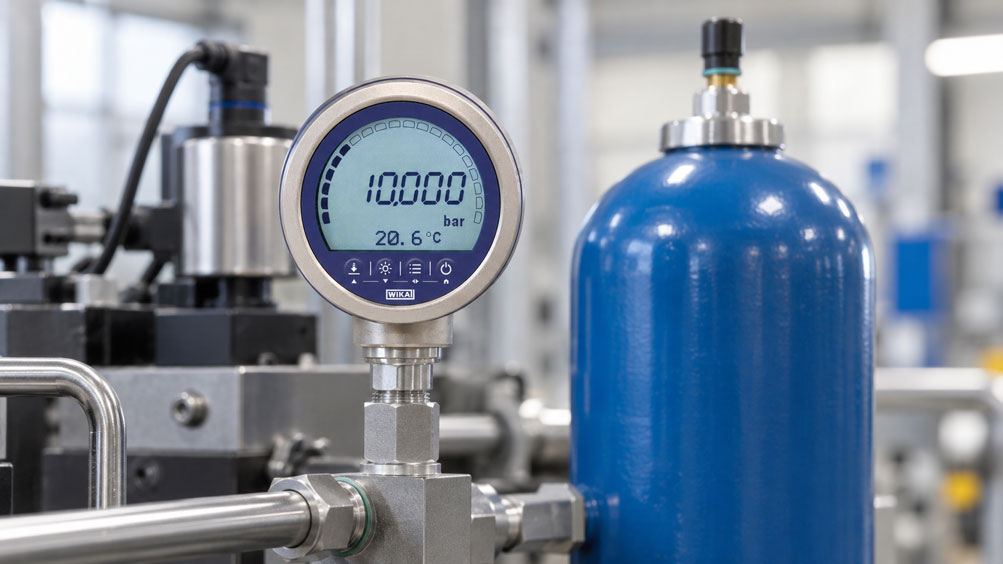
A hydraulic accumulator is intended to supply additional hydraulic fluid for a short period when system pressure drops. The pressure gauge installed on the system indicates 160 bar during operation. However, subsequent maintenance reveals a nitrogen precharge pressure of only 80 bar. Is there a fault, has the accumulator been charged incorrectly, or are two fundamentally different operating conditions being compared?
The answer lies in the operating principle of the hydraulic accumulator. Gas precharge pressure describes the nitrogen pressure when the fluid side of the accumulator is completely depressurised hydraulically under the specified test conditions. During operation, however, hydraulic fluid flows into the accumulator and compresses the gas cushion. The gas pressure consequently increases and is approximately in static equilibrium with the hydraulic pressure.
A hydraulic pressure sensor therefore primarily measures the operating pressure at its measurement point. The original gas precharge pressure cannot be determined from this value without additional information. Conversely, a normal operating pressure reading does not automatically mean that sufficient nitrogen is present or that the accumulator can provide its intended usable oil volume.
This technical article explains the differences between gas precharge, accumulator charging pressure and hydraulic operating pressure. A calculation example demonstrates how gas volume changes at different pressure conditions. The article also discusses typical faults and the selection of suitable pressure transducers, digital pressure gauges and test connections. The focus is on meaningful pressure monitoring, reproducible diagnostics and safe handling of stored hydraulic energy.
Table of Contents
- Define the Hydraulic Accumulator Monitoring Task
- Distinguish Bladder, Piston and Diaphragm Accumulators
- Understand Gas Cushions and Hydraulic Energy Storage
- Distinguish Gas Precharge Pressure, Minimum Pressure and Maximum Pressure
- Why Gas Pressure and Hydraulic Pressure Are Similar During Operation
- Correctly Check the Actual Gas Precharge Pressure
- Consider the Influence of Temperature on Nitrogen Precharge Pressure
- Calculate the Relationship Between Gas Pressure and Gas Volume
- Calculation Example: Hydraulic Accumulator Between 100 and 160 bar
- Recognise the Effects of Insufficient Precharge Pressure
- Correctly Evaluate Excessive Precharge Pressure
- Select the Correct Hydraulic Pressure Measurement Point
- Select the Measuring Range and Pressure Sensor for the Accumulator
- Capture Pressure Spikes, Pulsations and Dynamic Pressure Changes
- Monitor Pump Switching Points and Hydraulic Pressure Limits
- Use Pressure-Time Profiles for Accumulator Diagnostics
- Distinguish Gas Loss, Hydraulic Leaks and Valve Faults
- Consider Process Connections, Test Couplings and Installation
- Safely Manage Nitrogen, Residual Pressure and Stored Hydraulic Energy
- Perform a Systematic Testing and Diagnostic Procedure
- Identify Typical Fault Patterns and Misinterpretations
- Suitable Pressure Measurement and Accumulator Testing Equipment from ICS Schneider
- Conclusion: Monitor Operating Pressure and Check Gas Precharge Separately
- Frequently Asked Questions About Hydraulic Accumulator Pressure Monitoring
1. Define the Hydraulic Accumulator Monitoring Task
Hydraulic accumulators perform different functions in industrial hydraulic systems. They can temporarily store hydraulic energy, provide short-duration flow rates, damp pressure fluctuations or supply a limited quantity of fluid when pump delivery is temporarily unavailable.
Typical applications include hydraulic presses, machine tools, injection moulding machines, mobile machinery, test benches and systems with recurring load changes.
Before selecting pressure measurement equipment, it is necessary to define which accumulator function is to be monitored. For an energy storage accumulator, the upper and lower operating pressures and available oil volume are decisive, for example. For a pulsation damper, rapid pressure changes and system dynamics are more important.
Gas precharge pressure must be considered separately. It significantly determines how much hydraulic energy or usable fluid volume the accumulator can provide within the intended operating range.
Reliable monitoring therefore requires different types of information: the current hydraulic pressure, its time-dependent profile, the specified gas precharge pressure and, where appropriate, additional operating parameters such as temperature, pump status and switching states.
It is particularly important to recognise that a pressure measurement point only measures the pressure at its actual location. If a closed shut-off valve is located between the pressure sensor and the accumulator, the sensor may indicate a different pressure from that currently present inside the accumulator.
The measurement task must therefore be considered when designing the hydraulic circuit and positioning the sensors.
2. Distinguish Bladder, Piston and Diaphragm Accumulators
Bladder, piston and diaphragm accumulators are the most common types used in hydraulic systems. All three types store hydraulic energy by compressing a gas volume. However, the separation between the gas and hydraulic fluid is achieved in different ways.
A bladder accumulator contains an elastic gas bladder inside a pressure-resistant vessel. The nitrogen is contained within the bladder, while hydraulic fluid enters the accumulator outside the bladder. As hydraulic pressure increases, the bladder is compressed.
In a piston accumulator, a moving piston separates the gas chamber from the fluid chamber. The piston position changes depending on pressure and the stored fluid volume. Piston friction and seal characteristics can influence dynamic behaviour.
A diaphragm accumulator uses a flexible diaphragm to separate the two media. This design is frequently used for more compact accumulator sizes and certain damping or compensation tasks.
For all three types, gas precharge and hydraulic operating loads must be evaluated separately.
The permissible pressure ratios between precharge pressure, minimum operating pressure and maximum operating pressure differ depending on accumulator type and manufacturer.
Particularly with diaphragm and bladder accumulators, it is important to prevent the separating element from repeatedly contacting a mechanical stop or the fluid connection under unsuitable pressure conditions.
With piston accumulators, possible friction and sealing effects must also be considered. The behaviour of one accumulator design must therefore not automatically be applied to all other designs.
3. Understand Gas Cushions and Hydraulic Energy Storage
A hydraulic accumulator uses a compressible gas cushion to absorb energy within a hydraulic system and release it again later.
In the unloaded, hydraulically depressurised condition, the accumulator has a defined gas precharge pressure. The gas occupies the volume specified for this condition.
When hydraulic pressure rises above the effective gas pressure, hydraulic fluid can flow into the accumulator. This reduces the gas volume and increases the gas pressure.
When the system subsequently requires additional hydraulic fluid, the compressed gas can force the stored fluid back into the hydraulic system. The gas volume increases again and the pressure decreases.
This process explains why a hydraulic accumulator cannot be considered equivalent to a rigid fluid reservoir.
The usable amount of energy depends particularly on the total accumulator volume, gas precharge pressure, upper and lower operating pressures and the thermodynamic behaviour of the gas.
The speed of the charging and discharging process is also relevant. During rapid processes, gas temperature may develop differently from that during slow compression or expansion.
Hydraulic pressure is therefore an important operating parameter, but it does not by itself describe the total amount of stored energy or the condition of the gas precharge.
4. Distinguish Gas Precharge Pressure, Minimum Pressure and Maximum Pressure
The quantities p0, p1 and p2 are commonly used for hydraulic accumulator design and diagnostics.
| Designation | Meaning | Measurement or Operating Condition |
|---|---|---|
| p0 – Gas precharge pressure | Nitrogen pressure in the specified precharge condition | Hydraulic side safely depressurised; gas pressure checked at the designated gas connection |
| p1 – Minimum operating pressure | Lower hydraulic pressure limit of the intended working range | Accumulator is still operating within the planned hydraulic working condition |
| p2 – Maximum operating pressure | Upper hydraulic pressure limit of the intended working range | Accumulator contains more hydraulic fluid according to its operating condition |
| V0 – Gas volume at p0 | Gas volume under the defined precharge condition | Reference condition for accumulator sizing |
| V1 – Gas volume at p1 | Gas volume at the lower operating pressure | Gas cushion is compressed relative to its precharge condition |
| V2 – Gas volume at p2 | Gas volume at the upper operating pressure | Gas cushion has a smaller volume than at p1 |
In a typical energy storage application, the gas precharge pressure is below the intended minimum operating pressure.
For certain applications, HYDAC recommends a precharge pressure of 0.9 · p1, for example. This is a manufacturer- and application-specific design recommendation, not a universal requirement for all hydraulic accumulators.
Different pressure ratios may be appropriate for pulsation damping or shock absorption.
The quantities p0, p1 and p2 must therefore not be treated as equivalent. They describe different accumulator conditions and functions.
The permissible mechanical operating limits must also be observed separately. The selected upper operating pressure must remain within the approved limits of the accumulator and all connected components.
5. Why Gas Pressure and Hydraulic Pressure Are Similar During Operation
In a functioning hydraulic accumulator, the separating element transfers pressure forces between the gas and hydraulic fluid.
Under approximately static equilibrium conditions, with the accumulator appropriately charged, gas pressure and hydraulic pressure are often nearly equal.
For example, if a bladder accumulator operates at a hydraulic pressure of 150 bar, the gas pressure inside the compressed bladder may also be approximately 150 bar.
However, this value is not the same as the original gas precharge pressure.
The nitrogen has been compressed by the incoming hydraulic fluid. Its current pressure is therefore higher than in the unloaded precharge condition.
In a piston accumulator, additional pressure differences can arise from piston friction and dynamic movement. During rapid pressure changes, flow resistance, inertia and pressure losses may also affect the instantaneous measured values.
Consequently, gas pressure during operation cannot always be treated as exactly equal to hydraulic pressure.
The pressure sensor location is particularly important. If a sensor is positioned upstream of an isolation valve, it may measure only the system pressure on its own side when the valve is closed. The accumulator itself may remain at a different pressure.
A hydraulic pressure reading of 150 bar, for example, therefore does not directly reveal whether the accumulator was originally precharged with nitrogen to 70, 80 or 90 bar.
Determining the actual precharge pressure requires a separate test unless an expressly designed and appropriately validated accumulator monitoring system is used for this purpose.
6. Correctly Check the Actual Gas Precharge Pressure
Gas precharge pressure is checked through the accumulator’s designated gas connection.
The condition of the hydraulic system is essential. For a conventional precharge pressure test, the accumulator must be isolated from the hydraulic system and its fluid side must be safely and completely depressurised in accordance with the manufacturer’s instructions.
Only then does the reading at the gas valve represent the gas precharge pressure under the intended test conditions.
If the gas side is checked while the hydraulic fluid is still pressurised and compressing the gas, the measurement indicates the current gas pressure of the loaded accumulator. This may be significantly higher than the actual precharge pressure.
Suitable charging and testing assemblies are used during maintenance. They provide the necessary connections and functions for controlled testing, filling where required, and safe depressurisation of the testing assembly.
The MINIMESS accumulator charging and testing assembly offered by ICS is designed for corresponding service operations.
The gas charging and testing device with pressure reducing valve is also intended for controlled filling and pressure testing of nitrogen-charged hydraulic accumulators.
The actual testing procedure depends on the accumulator manufacturer, the equipment used and the applicable safety requirements.
During the actual precharge pressure measurement, the gas side naturally remains pressurised at the nitrogen pressure being measured. This must be distinguished from dismantling or repair work, which may require complete depressurisation of both sides depending on the work involved.
Detailed information about filling valves and maintenance is provided in the complementary ICS technical article Hydraulic Accumulators: Checking and Charging Nitrogen – Using Gas Charging Valves Correctly.
7. Consider the Influence of Temperature on Nitrogen Precharge Pressure
Gas precharge pressure depends on the temperature of the nitrogen. An accumulator may therefore indicate different gas pressures at different temperatures even though no nitrogen has been lost.
For an initial assessment at constant gas volume, the ideal gas law can be used:
p0,2,abs = p0,1,abs · T2 / T1
Pressures must be expressed as absolute pressures. Temperatures are entered in kelvin.
Consider a hydraulically depressurised accumulator with a gauge precharge pressure of 80 bar at 20 °C. Assuming an ambient pressure of 1 bar for simplicity, the absolute gas pressure is approximately 81 bar.
If the gas temperature increases to 40 °C while its volume remains unchanged, the result is:
p0,40°C,abs ≈ 81 bar · 313.15 K / 293.15 K ≈ 86.5 bar abs.
Assuming an ambient pressure of 1 bar, this corresponds to approximately 85.5 bar gauge pressure.
In this simplified model, the indicated precharge pressure has increased by approximately 5.5 bar solely because of the temperature change.
The example demonstrates why test results can only be compared meaningfully when temperature is known.
Sufficient thermal stabilisation is particularly important after a filling operation. Temperature and pressure may continue to change initially as a result of the filling process.
A gas pressure reading taken too early may therefore differ from the subsequent equilibrium condition.
At high pressures and in demanding design applications, deviations from ideal gas behaviour may become relevant. Manufacturers such as HYDAC also account for real gas behaviour in their design procedures.
The simplified temperature calculation is therefore intended to illustrate the principle and does not replace the manufacturer’s calculation for the specific accumulator.
8. Calculate the Relationship Between Gas Pressure and Gas Volume
Energy storage in a hydraulic accumulator is based on compression of the gas cushion.
For a simplified polytropic model, the following relationship can be used:
p · Vn = constant
Here, p is the absolute gas pressure, V is the gas volume and n is the polytropic exponent assumed for the process being considered.
For an idealised slow, isothermal change of state with approximately constant gas temperature, n = 1.
For rapid processes with negligible heat exchange, an approximately adiabatic change of state can be assumed. For ideal diatomic nitrogen, an exponent of approximately 1.4 is frequently used.
Depending on their design, temperature, cycle duration and heat transfer, real hydraulic accumulators do not necessarily behave according to one constant exponent.
The simplified relationship gives:
V1 = V0 · (p0,abs / p1,abs)1/n
and
V2 = V0 · (p0,abs / p2,abs)1/n
In the idealised model, the usable fluid volume available from the accumulator between the considered pressure states is calculated from the difference between the gas volumes:
ΔV = V1 − V2
This relationship demonstrates that the usable oil volume does not depend solely on the upper hydraulic pressure. The original gas precharge pressure also influences accumulator behaviour between the two pressure states.
Accurate sizing must account for additional limitations of the specific accumulator design. These include permissible pressure ratios, minimum volumes, mechanical limits and the thermal behaviour of nitrogen.
9. Calculation Example: Hydraulic Accumulator Between 100 and 160 bar
A simplified example considers a hydraulic accumulator with a usable reference gas volume of 10 litres.
The gas precharge pressure is 80 bar gauge at the specified reference temperature. The hydraulic operating pressure varies between 100 and 160 bar gauge.
For this example, a slow, approximately isothermal change of state with n = 1 is assumed. Atmospheric pressure is also simplified to 1 bar.
This gives the following absolute pressures:
p0,abs = 81 bar
p1,abs = 101 bar
p2,abs = 161 bar
The gas volume at the lower hydraulic operating pressure is:
V1 = 10 l · 81 / 101 ≈ 8.02 l
At the upper hydraulic operating pressure, the gas volume is:
V2 = 10 l · 81 / 161 ≈ 5.03 l
The theoretical usable fluid volume between these pressure states is therefore:
ΔV = 8.02 l − 5.03 l ≈ 2.99 l
The table also illustrates how a lower gas precharge pressure would affect the same simplified model.
| Parameter | Case A: 80 bar Precharge | Case B: 60 bar Precharge |
|---|---|---|
| Reference gas volume V0 | 10.0 l | 10.0 l |
| Gas precharge pressure p0 | 80 bar gauge | 60 bar gauge |
| Minimum hydraulic pressure p1 | 100 bar gauge | 100 bar gauge |
| Maximum hydraulic pressure p2 | 160 bar gauge | 160 bar gauge |
| Gas volume at p1 | approx. 8.02 l | approx. 6.04 l |
| Gas volume at p2 | approx. 5.03 l | approx. 3.79 l |
| Theoretical usable fluid volume | approx. 2.99 l | approx. 2.25 l |
The comparison shows that a lower gas precharge pressure does not automatically provide a larger usable oil volume when the hydraulic pressure limits remain unchanged.
In the example, the fluid volume available between 100 and 160 bar decreases from approximately 2.99 to 2.25 litres.
The accumulator may nevertheless reach 160 bar during hydraulic operation. The pressure sensor may therefore indicate a completely normal upper operating pressure even though the usable fluid reserve has decreased compared with the intended condition.
This is the essential distinction between operating pressure and gas precharge.
The results apply exclusively to the simplified isothermal calculation model. Rapid charging and discharging processes produce different volume values because of their thermal behaviour.
Mechanical and design-related limitations may also prevent the entire theoretically calculated fluid volume from being used.
The actual accumulator must therefore be sized and evaluated in accordance with the respective manufacturer’s specifications.
10. Recognise the Effects of Insufficient Precharge Pressure
Insufficient gas precharge pressure can significantly impair the function of a hydraulic accumulator.
In an energy storage accumulator, the usable oil volume within the intended pressure range may decrease. The system then has less hydraulic reserve than originally designed.
This may, for example, cause a pump to switch on more frequently, shorten the pressure holding period or prevent a hydraulic function from being supplied for a sufficiently long time.
In pulsation damping applications, an unsuitable gas precharge can change the damping effect. Stronger pressure fluctuations may consequently occur within the system.
Persistently low precharge pressure may also result in greater deformation of the separating element than intended under unfavourable operating conditions.
In a bladder accumulator, improper operation can place mechanical stress on the bladder, for example. Different wear and movement problems may occur in piston accumulators.
Gas loss may result from leaks at the gas charging valve, seals or other defects. Damage to the separating element is another possibility.
An unusual hydraulic pressure profile may indicate a precharge problem. However, it does not provide definitive proof.
Similar symptoms may be caused by internal leaks, valve problems, changes in pump delivery or changes in hydraulic fluid demand.
The gas precharge must therefore be checked separately to establish a reliable diagnosis.
11. Correctly Evaluate Excessive Precharge Pressure
Excessive gas precharge pressure can be just as problematic as insufficient precharge pressure.
If the precharge pressure reaches or exceeds the intended lower hydraulic operating pressure, accumulator behaviour may differ significantly from its planned operating condition.
Below the effective gas pressure, little or no hydraulic fluid may enter the accumulator.
Consequently, the accumulator may not be available to the required extent for its intended energy delivery or pressure damping function.
During discharge, the separating element may also reach a mechanical end position before the intended minimum hydraulic pressure is reached.
With unsuitable design conditions, such states can cause undesirable mechanical loading.
High precharge pressure does not therefore automatically mean that a particularly large amount of energy can be stored.
The suitable gas precharge depends on the accumulator type, operating pressure range, intended function and permissible pressure ratios.
A general percentage such as 90 % of the lower operating pressure is also not valid for every accumulator application.
The correct precharge pressure must be determined from the manufacturer’s calculation or the technical design of the installation.
12. Select the Correct Hydraulic Pressure Measurement Point
The position of a pressure sensor is decisive for the significance of hydraulic accumulator monitoring.
If the actual hydraulic pressure at the accumulator is to be measured, the measurement point must be connected to the designated hydraulic accumulator port.
In many installations, a suitable safety or shut-off block is located between the accumulator and the rest of the hydraulic system.
This block may incorporate various valve and safety functions. Its specific design depends on the accumulator and application.
If the pressure sensor is installed on the system side of an isolation valve, it may measure a different pressure from that inside the accumulator when the valve is closed.
To monitor the actual accumulator condition, a measurement point on the designated accumulator side of the relevant isolation device may therefore be necessary.
Its position must be coordinated with the hydraulic circuit design and safety requirements.
The height of the measurement point can also cause hydrostatic effects in large vertical installations. A pressure difference may exist between two measurement points at different heights when the fluid is stationary.
Additional pressure losses occur during dynamic flow.
Both the position of the sensor and the operating state of the valves must therefore be known for meaningful measurement.
The hydraulic pressure measurement point must also not be confused with the separate nitrogen charging connection.
A pressure sensor at the oil port does not automatically measure gas precharge pressure.
13. Select the Measuring Range and Pressure Sensor for the Accumulator
A pressure transmitter for hydraulic monitoring must be suitable for the actual operating pressure and the maximum possible loading conditions.
Selection requires information about the normal operating range, maximum permissible operating pressure, possible pressure spikes and measurement accuracy requirements.
Overpressure resistance and the permissible number of pressure load cycles may also be relevant.
Consider a hydraulic system normally operating between 100 and 160 bar. A suitably specified pressure sensor with a measuring range of 0 … 200 or 0 … 250 bar, for example, could be considered for this application.
However, actual selection must not be based solely on the upper operating pressure.
If substantially higher pressures occur briefly during valve switching, these loads must also be taken into account.
A larger measuring range improves the potential operating margin but may reduce resolution and increase absolute measurement uncertainty when detecting smaller pressure changes.
Long-term pressure monitoring therefore requires a suitable balance between measuring range, accuracy, dynamic load capacity and mechanical robustness.
The WIKA S-20 offers different measuring ranges and output signals and is suitable for demanding industrial pressure measurement applications.
The Druck UNIK 5000 provides additional configuration options concerning measuring range, electrical connection and pressure measurement type.
Both sensor families may be suitable for appropriate hydraulic measurement points. However, the specific media compatibility, pressure resistance and connection configuration must be checked for the selected model.
14. Capture Pressure Spikes, Pulsations and Dynamic Pressure Changes
Hydraulic accumulators are frequently used to influence dynamic pressure changes. The time resolution of pressure measurement can therefore be particularly important.
For basic operating pressure monitoring, a pressure display with a relatively slow update rate may be sufficient.
Investigating short pressure spikes or rapid pressure pulsations, however, may require significantly higher measurement bandwidth and sampling rates.
A pressure sensor may be capable of capturing rapid pressure changes while the downstream controller processes measured values only slowly.
Electronic damping can also cause short pressure spikes to be barely visible on the display.
The complete measurement chain must therefore be considered: pressure sensor, signal conditioning, data transmission, controller and recording system.
Depending on its configuration, the UNIK 5000 is designed for high-frequency response and may therefore be suitable for certain dynamic pressure measurements.
Whether the actual configuration captures a particular pressure spike sufficiently quickly depends on factors including the sensor variant and connected data acquisition system.
The mechanical measurement connection also influences the result. Long measurement hoses, additional trapped gas volumes or unsuitable pressure tapping points can alter pressure oscillations or introduce additional resonance effects.
An apparently stable pressure profile therefore does not necessarily mean that no rapid pressure events occur at the accumulator.
During diagnosis, measurement bandwidth and time resolution should match the frequency and duration of the expected pressure changes.
15. Monitor Pump Switching Points and Hydraulic Pressure Limits
In many energy storage applications, the hydraulic accumulator is charged by a hydraulic pump. Once the system reaches the intended upper pressure value, the pump may be switched off or unloaded, for example.
When pressure subsequently falls to a lower value, the pump may start again.
These two switching points are frequently monitored using a pressure sensor, electronic pressure switch or suitable mechanical pressure switch.
For a system operating between 100 and 160 bar, the intended upper and lower switching points may be located within this range, for example.
The actual limit values must be derived from the hydraulic system design.
A switching point is not automatically equivalent to the gas precharge pressure.
Hysteresis in pressure monitoring is also important. An unsuitable setting may cause frequent pump switching.
For diagnosis, it is therefore useful to know how frequently the pump starts, how long charging takes and how quickly pressure falls again after the pump has been switched off.
Changes in these parameters over time may indicate altered accumulator performance.
However, hydraulic leaks, other consumers, pump wear or valve problems can also influence this behaviour.
Continuous monitoring of pump switching points is therefore a useful part of condition diagnostics but does not replace an actual gas precharge pressure test.
16. Use Pressure-Time Profiles for Accumulator Diagnostics
Continuous pressure recording can provide valuable information about the condition of a hydraulic accumulator.
The time-dependent profile between the upper and lower operating pressures is often particularly informative.
For a defined load, for example, the time required for the accumulator to discharge from 160 to 100 bar can be measured.
If this time becomes shorter across several comparable tests, the available hydraulic energy may have decreased.
One possible cause is loss of nitrogen precharge. However, other causes are also possible, such as additional hydraulic leakage or a change in fluid consumption.
The actual volume of fluid withdrawn or the operating condition must therefore be known if the pressure profile is to be evaluated quantitatively.
The pressure increase during charging can also provide useful information.
A significant change in pressure rise time may indicate an altered interaction between pump delivery, accumulator charging and hydraulic fluid consumption.
During appropriately slow, controlled discharge, characteristic changes in the pressure-volume curve may occur in certain installations as the accumulator reaches its discharged condition.
Under suitable conditions, such changes can provide information about the effective gas precharge pressure.
However, indirect determination from the hydraulic pressure curve is only reliable if the procedure is intended and validated for the accumulator type and specific installation.
Piston friction, dynamic pressure losses, temperature changes and the hydraulic circuit configuration can all affect the result.
For routine diagnostics, a combination of pressure trends, pump status and, where appropriate, other process data is therefore particularly useful.
17. Distinguish Gas Loss, Hydraulic Leaks and Valve Faults
A pressure decrease in a hydraulic system does not necessarily result from loss of gas precharge.
Internal leakage through a valve, a leaking cylinder or a damaged seal can also change hydraulic pressure.
If the hydraulic accumulator provides less oil than expected, it is therefore necessary to distinguish between a problem on the gas side and a problem within the hydraulic circuit.
For example, low gas precharge pressure may reduce the usable oil volume within the intended operating range.
Internal hydraulic leakage, on the other hand, can cause the available fluid reserve to be consumed more quickly.
Both faults may result in more frequent pump switching or shorter pressure holding periods.
A check valve that does not close completely can also cause an unexpected pressure decrease.
With piston accumulators, possible internal leakage between the gas and fluid chambers must additionally be considered.
In bladder or diaphragm accumulators, damage to the separating element can significantly impair operation.
Reliable diagnosis therefore requires more than a single pressure reading.
A separate gas precharge check, investigation of hydraulic valves and additional diagnostic procedures specified by the manufacturer may be necessary.
It is important that each test is performed only under the appropriate safe system conditions.
18. Consider Process Connections, Test Couplings and Installation
The mechanical connection of a pressure sensor must be compatible with the existing hydraulic port.
Relevant factors include the connection thread, sealing principle, permissible pressure, temperature and hydraulic fluid used.
A thread alone does not guarantee correct sealing. Depending on the connection type, sealing may be provided by an O-ring, flat gasket, metallic sealing cone or another defined sealing surface.
An incorrect combination of connection and sealing element can cause leaks or mechanical damage.
Suitable hydraulic test couplings can be useful for recurring service tests. They allow a test pressure gauge or measurement line to be connected to the designated measurement point.
For the gas side of a hydraulic accumulator, however, specially designed gas charging valves and corresponding charging and testing equipment are required.
These two connection types must not be confused.
For example, ICS offers the Original MINIMESS 1615 gas charging valve with accumulator adapter. It is designed for corresponding gas service connections on bladder accumulators and is available in suitable versions for operating pressures up to 400 bar.
Actual suitability must be checked against the specific accumulator, connection and approved operating conditions.
A hydraulic test connection must also have appropriate pressure resistance and media compatibility. Where a measurement hose is used, its permissible pressure, seals, couplings and dynamic load capacity must be considered.
An unnecessarily long measurement hose can also affect dynamic pressure measurement.
Mechanical installation is therefore an essential part of measurement safety, not merely a matter of matching thread dimensions.
19. Safely Manage Nitrogen, Residual Pressure and Stored Hydraulic Energy
Hydraulic accumulators can store substantial amounts of energy. This remains true even when the hydraulic pump is switched off and the electrical system is de-energised.
A stopped drive therefore does not automatically mean that the accumulator is depressurised.
Before testing, maintenance or repair work, the necessary safe system conditions must be established and verified according to the manufacturer’s instructions.
Hydraulic residual pressures and the respective conditions of the gas and fluid sides must be considered in particular.
Conventional gas precharge pressure testing requires safe depressurisation of the hydraulic side. The nitrogen itself remains under pressure during the intended measurement.
Work involving removal of the accumulator, opening the gas chamber or other interventions may require additional measures to depressurise the system completely.
Only gases approved by the accumulator manufacturer may be used for charging. For conventional nitrogen-precharged hydraulic accumulators, nitrogen of the specified quality is required.
Oxygen or compressed air must not be used as a substitute for nitrogen. This can cause dangerous reactions, particularly in combination with hydraulic oil, and create serious safety risks.
Suitable charging and testing equipment, approved connections and, where required, pressure reducing valves must be used for filling.
The permissible pressures and required procedure must correspond to the specific accumulator.
Uncontrolled opening of a gas charging valve or loosening a pressurised connection is also prohibited.
Relevant standards include DIN EN 14359:2017 for corresponding gas-loaded accumulators and ISO 4413:2010 for general safety requirements relating to hydraulic systems.
Depending on the design and application, the Pressure Equipment Directive 2014/68/EU may impose additional requirements concerning pressure equipment and conformity.
Specific testing and maintenance must always comply with applicable regulations and the accumulator manufacturer’s instructions.
20. Perform a Systematic Testing and Diagnostic Procedure
For meaningful accumulator diagnostics, hydraulic operating pressure monitoring and gas precharge pressure testing should be deliberately treated as separate tasks.
The following procedure describes a general testing structure. Actual implementation requires appropriately qualified personnel and a safe procedure approved for the installation.
- Identify the accumulator: Record the design, manufacturer, model, accumulator volume, permissible pressure and available documentation.
- Define the test objective: Distinguish whether hydraulic operating pressure is to be monitored or the actual gas precharge pressure is to be checked.
- Document the hydraulic circuit: Clearly identify the accumulator connection, isolation valves, safety block, pressure sensors and possible test couplings.
- Record operating data: Determine the specified gas precharge pressure, minimum and maximum hydraulic pressures and permissible temperature conditions.
- Check pressure measurement equipment: Evaluate measuring range, accuracy, calibration status, process connection and time-dependent measurement behaviour.
- Record the hydraulic pressure profile: Document charging and discharging processes under suitable, safe operating conditions.
- Identify pump and valve states: Evaluate switching points, charging times and any pressure holding periods.
- Verify the plausibility of measured values: Check whether the pressure sensor and accumulator are actually hydraulically connected under the valve positions being considered.
- Document temperature conditions: Record relevant operating and testing temperatures.
- Prepare separate precharge pressure testing: Define the manufacturer procedure, required charging and testing equipment and safety measures.
- Safely depressurise the hydraulic side: Isolate the accumulator hydraulically and completely depressurise it according to the manufacturer’s instructions before conventional gas precharge pressure testing.
- Check gas precharge pressure: Measure at the designated gas charging connection using approved equipment and the specified procedure.
- Consider temperature: Compare the measured precharge pressure with the specified reference value under comparable temperature conditions.
- Compare measurements: Document gas precharge pressure and hydraulic operating pressures as separate operating quantities.
- Identify the cause of faults: Where abnormalities occur, distinguish between gas loss, hydraulic leakage, valve faults and possible pressure measurement problems.
- Perform necessary corrective measures: Make required adjustments or repairs only in accordance with manufacturer approval.
- Repeat functional testing: After repairs, restore the intended safe operating condition and verify accumulator performance.
- Complete documentation: Record operating pressure, precharge pressure, temperature, test conditions and any defined follow-up measures.
It is particularly important that a normal hydraulic pressure reading is not recorded as a substitute for the measured gas precharge pressure.
Additional nitrogen should also not be introduced into the accumulator prematurely without checking the actual precharge pressure and the permissible manufacturer conditions.
Recurring inspection intervals must be defined according to manufacturer specifications, operating conditions and applicable regulations.
21. Identify Typical Fault Patterns and Misinterpretations
The following observations may indicate a change in accumulator condition. However, the actual cause must be established on the specific hydraulic system.
| Observation | Possible Cause | Suitable Check |
|---|---|---|
| Hydraulic pressure reaches the intended maximum, but usable oil volume is insufficient | Incorrect or reduced gas precharge pressure | Check gas precharge in the specified hydraulically depressurised condition |
| Pump switches on more frequently than before | Reduced accumulator reserve, changed fluid consumption or hydraulic leakage | Evaluate the pressure-time profile, consumption and actual precharge pressure separately |
| Hydraulic pressure decreases unusually quickly while the system is stationary | Internal leakage, leaking valve or altered accumulator performance | Investigate the hydraulic circuit and accumulator condition |
| Precharge pressure is higher when the system is warm than during a cold test | Temperature-dependent change in nitrogen pressure | Reference gas temperature and pressure to suitable comparison conditions |
| Gas pressure reading during hydraulic operation is considerably higher than the documented precharge pressure | Gas cushion has been compressed by hydraulic fluid | Interpret operating gas pressure and gas precharge pressure as different conditions |
| Pressure sensor still indicates pressure despite an unloaded accumulator circuit | Measurement point is on another side of a valve, or pressure remains trapped | Check measurement location, valve positions and safe elimination of residual pressure |
| Strong pressure pulsations occur despite an installed accumulator | Unsuitable precharge, incorrect accumulator sizing or dynamic system influences | Check gas precharge, frequency response and hydraulic circuit configuration |
| Pressure display is stable, but the system experiences shock loads | Measurement instrument or data acquisition may be too slow or excessively damped | Check measurement bandwidth, sampling rate and mechanical measurement connection |
| Precharge pressure decreases between recurring inspections | Possible nitrogen loss or different temperature conditions | Compare temperature-referenced test results and assess gas tightness according to the manufacturer’s procedure |
| Accumulator takes in very little fluid at the lower operating pressure | Gas precharge pressure may be too high | Check the intended pressure ratios and actual gas precharge pressure |
| Digital pressure gauge and pressure transmitter show different values | Different measurement points, pressure references, accuracies or signal errors | Compare measurement locations, gauge/absolute pressure and calibration status |
| Pressure profile changes noticeably after maintenance | Changed precharge, valve position, air in the hydraulic system or mechanical fault | Check the maintenance performed, gas precharge and hydraulic operating condition |
The table contains possible causes and suitable diagnostic approaches, but does not provide definitive proof of individual faults.
Distinguishing between gas loss and hydraulic leakage is particularly important. Both can result in a shorter pressure holding period, but they have different causes and require different corrective measures.
A changed pressure curve should therefore always be assessed in conjunction with actual fluid consumption, pump operation and accumulator condition.
22. Suitable Pressure Measurement and Accumulator Testing Equipment from ICS Schneider
22.1 Druck UNIK 5000: Configurable Pressure Sensor for Hydraulics and Mechanical Engineering
The Druck UNIK 5000 from Baker Hughes is a configurable pressure sensor platform for industrial pressure measurement.
The series offers different pressure measurement types, measuring ranges, output signals and mechanical connection options.
Depending on the configuration, pressure ranges up to 700 bar are available. Accuracy options extend to ±0.04 % of full scale according to BSL.
The series also features high overpressure resistance and, depending on the configuration, fast dynamic response.
For hydraulic accumulator pressure monitoring, the UNIK 5000 can be used, for example, to transmit the hydraulic operating pressure continuously to a controller or suitable data acquisition system.
Selection of the appropriate measurement bandwidth and output signal is particularly important for test benches and dynamic applications.
The sensor measures pressure at its hydraulic process connection. It therefore does not replace separate testing of nitrogen precharge pressure at the gas charging valve.
22.2 WIKA S-20: Industrial Pressure Transmitter for Hydraulic Applications
The WIKA S-20 is an industrial pressure transmitter for demanding applications in mechanical and plant engineering.
It features a robust design and different electrical and mechanical connection options.
The series offers measuring ranges from 0 … 0.4 bar to 0 … 1,600 bar. Depending on the configuration, 4 … 20 mA and various voltage outputs are available, for example.
The S-20 may be suitable for monitoring hydraulic operating pressure if the selected configuration is compatible with the fluid, pressure range and dynamic loading conditions.
In conjunction with a controller, minimum and maximum pressures can be monitored, and charging and discharging processes can be evaluated.
The exact installation position must be selected so that the measurement reflects the intended accumulator condition.
When installed hydraulically, this sensor also does not directly determine gas precharge pressure.
22.3 WIKA CPG1500: Precision Digital Pressure Gauge for Service and Pressure Testing
The WIKA CPG1500 is a battery-powered precision digital pressure gauge for maintenance, pressure testing and calibration tasks.
It is available with different measuring ranges up to 10,000 bar and, depending on the configuration, offers accuracy up to 0.025 % of full scale.
Functions include MIN/MAX recording, selectable pressure units and a data logging function with a recording rate of up to 50 values per second.
This makes the instrument suitable for corresponding reference and service measurements as well as time-dependent documentation of pressure changes.
A suitable pressure range and connection configuration are required for hydraulic accumulator maintenance.
When testing the nitrogen side, only suitable and approved gas connections and the designated accumulator charging and testing assemblies may be used.
The CPG1500 alone is not a complete accumulator charging and testing assembly.
22.4 MINIMESS Accumulator Charging and Testing Assembly: Checking Gas Precharge Pressure
The Original MINIMESS accumulator charging and testing assembly is designed for filling and checking suitable nitrogen-charged hydraulic accumulators.
It enables corresponding service work through the designated gas charging connection.
The assembly provides functions for controlled connection, testing and depressurisation according to the intended system arrangement.
During recurring maintenance, it can help check gas precharge pressure under defined conditions.
Selection depends particularly on the type of gas charging valve, maximum pressure, required adapters and manufacturer approval.
The technical distinction is important: The charging and testing assembly is used to check and, where necessary, adjust the gas precharge. A permanently installed hydraulic pressure sensor, on the other hand, provides continuous monitoring of operating pressure.
22.5 MINIMESS 1615: Gas Charging Valve with Accumulator Adapter
The Original MINIMESS 1615 gas charging valve with accumulator adapter is intended for suitable bladder accumulators.
It provides a defined gas service connection and is available in corresponding versions for operating pressures up to 400 bar.
Installation is performed at the designated gas connection of the accumulator.
Selection depends on the accumulator type, existing gas valve configuration and mechanical connection conditions.
The gas charging valve must not be confused with an ordinary hydraulic test connection.
The connection designed for the nitrogen side does not automatically serve as a measurement point for hydraulic operating pressure.
Other suitable components, including gas charging and testing devices with pressure reducing valves, are available within the MINIMESS product range from ICS Schneider.
An overview of further measuring instruments, pressure transducers and testing solutions is available in the Pressure Measurement category from ICS Schneider.
23. Conclusion: Monitor Operating Pressure and Check Gas Precharge Separately
A hydraulic accumulator has different pressure conditions that must not be confused.
Gas precharge pressure describes the nitrogen pressure in the specified hydraulically depressurised reference condition. During operation, the gas is compressed by incoming hydraulic fluid. The gas pressure increases and, under suitable conditions, is approximately in equilibrium with the hydraulic pressure.
A pressure sensor on the fluid side therefore measures the current hydraulic operating pressure, but not automatically the original gas precharge.
A normal upper operating pressure reading also does not prove that the accumulator has its intended fluid reserve.
For reliable diagnosis, the hydraulic pressure profile, accumulator function and actual gas precharge pressure must be considered separately.
Documentation of charging and discharging times, pump switching points and, where appropriate, the actual volume of oil withdrawn is particularly useful.
Temperature is another important factor. Even a relatively small temperature change can noticeably alter nitrogen precharge pressure.
Safe maintenance also requires the charging and testing equipment specified by the manufacturer, together with the prescribed depressurisation and safety measures.
Identify the accumulator type → Distinguish gas precharge pressure from hydraulic pressure limits → Select the measurement point → Define measuring range and sensor technology → Monitor charging and discharging behaviour → Analyse abnormalities → Check gas precharge separately under the specified depressurised condition → Consider temperature → Evaluate accumulator performance → Document the results
The most important practical principle is therefore: Hydraulic operating pressure describes the current condition of the system. Gas precharge pressure largely determines the available accumulator reserve. Both values are related but must be measured and evaluated under different conditions.
24. Frequently Asked Questions About Hydraulic Accumulator Pressure Monitoring
24.1 What Is the Difference Between Gas Precharge Pressure and Hydraulic Operating Pressure?
Gas precharge pressure describes the nitrogen pressure under the intended precharge conditions when the fluid side is hydraulically depressurised. Hydraulic operating pressure, on the other hand, describes pressure during system operation. When hydraulic fluid enters the accumulator, the gas is compressed and its pressure increases.
24.2 Why Does the Hydraulic Accumulator Show 160 bar During Operation When Its Precharge Pressure Is Only 80 bar?
The hydraulic fluid compresses the nitrogen during accumulator charging. Under approximately static equilibrium conditions, gas pressure and hydraulic operating pressure may be nearly equal. However, the original precharge pressure of 80 bar describes a different, hydraulically depressurised condition.
24.3 Can I Measure Gas Precharge Pressure with a Hydraulic Pressure Sensor?
A hydraulic pressure sensor initially measures the pressure at its hydraulic measurement point. Gas precharge pressure cannot be reliably determined from the current operating pressure alone. Conventional precharge testing requires a separate measurement at the designated gas connection under hydraulically depressurised conditions.
24.4 Why Must the Hydraulic Side Be Depressurised Before Checking Precharge Pressure?
As long as hydraulic fluid compresses the gas cushion, the current gas pressure is higher than the original precharge pressure. This influence must be eliminated according to the manufacturer’s procedure to measure precharge correctly. The fluid side must therefore be safely and completely depressurised.
24.5 What Is the Correct Gas Precharge Pressure for a Hydraulic Accumulator?
The appropriate precharge pressure depends on the accumulator design, function, minimum and maximum operating pressures, and temperature conditions. For certain energy storage applications, HYDAC recommends a precharge pressure of approximately 90 % of the minimum operating pressure. However, this value does not apply universally to all hydraulic accumulators.
24.6 What Happens if the Gas Precharge Pressure Is Too Low?
Insufficient precharge pressure can reduce the usable fluid volume within the intended operating pressure range. This can result in shorter pressure holding periods, more frequent pump switching and reduced damping performance. Unfavourable loading of the separating element may also occur.
24.7 What Happens if the Gas Precharge Pressure Is Too High?
If precharge pressure is too high relative to the intended minimum operating pressure, the accumulator may take in or release very little hydraulic fluid under certain operating conditions. Unfavourable mechanical end positions of the separating element may also occur.
24.8 Why Does Nitrogen Precharge Pressure Change with Temperature?
When the gas quantity remains unchanged and the gas volume is approximately constant, gas pressure increases with temperature and decreases as the gas cools. Precharge measurements must therefore be evaluated under known or comparable temperature conditions.
24.9 How Can the Usable Oil Volume of a Hydraulic Accumulator Be Calculated?
The polytropic gas equation can be used for simplified sizing. Gas volumes at the respective operating conditions are calculated from precharge pressure, reference volume and the lower and upper operating pressures. In the idealised model, their difference describes the usable fluid volume. Accurate sizing must comply with the manufacturer’s specifications.
24.10 What Is the Difference Between Isothermal and Adiabatic Accumulator Calculations?
An isothermal calculation assumes approximately constant gas temperature and is suitable as a model for slow processes. An adiabatic model approximately describes rapid compression or expansion with little heat exchange. Real accumulators may deviate from these idealised conditions.
24.11 Why Does the Hydraulic Pump Switch On More Frequently Than Before?
Possible causes include reduced usable accumulator reserve, changed hydraulic fluid demand or internal leakage. Gas loss is one possible explanation, but not the only one. The pressure profile, pump function and gas precharge must be checked separately for diagnosis.
24.12 Can a Hydraulic Accumulator Still Show Normal Operating Pressure Despite a Loss of Nitrogen Precharge?
Yes. Under certain conditions, the hydraulic pump may still generate normal system pressure. However, this does not mean that the accumulator is still performing its intended function. Without a sufficiently effective gas cushion, its ability to absorb and release energy may be substantially impaired.
24.13 Where Should a Pressure Sensor Be Installed on a Hydraulic Accumulator?
The pressure sensor must be installed at a hydraulic measurement point that actually reflects the intended accumulator condition. Particularly with safety and isolation blocks, it is important to know which side of a valve the measurement point is located on. Its position must be coordinated with the hydraulic circuit.
24.14 Which Pressure Measuring Range Is Suitable for a Hydraulic Accumulator Operating at 160 bar?
For a corresponding operating range, a sensor with a measuring range of 0 … 200 or 0 … 250 bar may be suitable, for example. Actual selection depends on maximum pressure spikes, overload resistance, measurement uncertainty and the permissible limits of the particular system.
24.15 Can I Assess the Condition of a Hydraulic Accumulator Using Pressure Recording?
Time-dependent pressure recording can provide useful information, for example about charging times, discharging times and pump switching cycles. However, the results also depend on pump performance, valves and hydraulic fluid demand. Gas precharge pressure cannot be determined unambiguously from the pressure curve alone without an appropriately validated method.
24.16 Why Must a Hydraulic Accumulator Not Be Charged with Compressed Air?
Nitrogen of the specified quality is required for conventional nitrogen-precharged hydraulic accumulators. Compressed air or oxygen can cause dangerous reactions, particularly in combination with hydraulic oil. Only gases approved by the accumulator manufacturer may be used.
24.17 Which Instruments Are Suitable for Pressure Monitoring and Precharge Testing?
Suitable configurations of the Druck UNIK 5000 or WIKA S-20 pressure sensor series can be used for continuous hydraulic pressure monitoring, for example. The WIKA CPG1500 is useful for service and reference measurements. Gas precharge testing requires suitable accumulator charging and testing assemblies, such as those available from the MINIMESS range offered by ICS Schneider.
24.18 What Information Does ICS Schneider Need for Equipment Selection?
The required information includes the accumulator design, manufacturer, volume and specified gas precharge pressure. The minimum and maximum hydraulic operating pressures, possible pressure spikes, temperature range, hydraulic fluid and intended measurement function are also important. Selecting pressure measurement equipment additionally requires the measuring range, accuracy, required dynamic response, process connection, electrical interface, installation conditions and any Ex requirements. If the gas precharge must also be checked, information about the exact gas valve configuration, available adapters, permissible charging pressures and requirements for charging and testing equipment and calibration must be provided.