


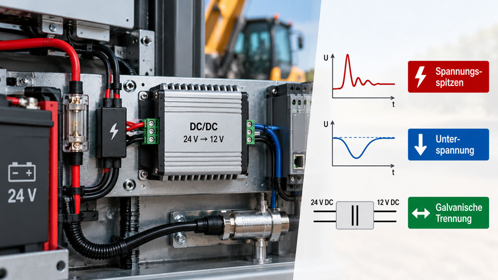
A DC/DC converter supplies sensors, control units or electronic measurement systems from a mobile 24 V electrical system. The power supply operates correctly in the laboratory. However, as soon as a large load is switched on or the vehicle engine starts, the connected measurement equipment briefly loses power. In other cases, the system initially operates reliably until a switching event causes an error message or damages the converter.
The cause is often not the rated output power but the electrical conditions of the mobile vehicle power system. A supply designated as 24 V does not maintain a constant voltage during operation. Voltage dips, load dump transients, reverse polarity risks, cable losses and electromagnetic interference can significantly affect the power supply. At the same time, sensitive sensors, communication modules and controllers have different requirements concerning ripple, ground reference and voltage stability.
A suitable DC/DC converter must therefore do more than simply convert one input voltage into another output voltage. Its input voltage range, protection circuitry, undervoltage behaviour, response to load transients and, where necessary, galvanic isolation must be matched to the actual application. This technical article explains the most important relationships and shows how to design, test and document a reliable power supply for mobile measurement and control equipment.
Table of Contents
- Define the Power Supply Requirements of the Mobile System
- Why a Mobile 24 V Electrical System Is Not a Constant 24 V Source
- Distinguish Input Voltage Spikes, Voltage Dips and Other Electrical Events
- Correctly Assess the Input Voltage Range and Voltage Withstand Capability
- Manage Undervoltage During Engine Starting and Load Changes
- Limit Load Dump and Transient Overvoltages
- Coordinate Reverse Polarity Protection, Fuses and Input Protection
- Understand Galvanic Isolation and Ground Potentials
- Distinguish Buck, Boost and 24 V-to-24 V Converters
- Correctly Size Output Power and Input Current
- Calculate Cable Losses and Voltage Drop
- Account for Inrush Current and Capacitive Loads
- Test Load Transients, Overload and Start-Up Behaviour
- Plan Ground Connections, Return Currents and Shielding
- Evaluate EMC and Vehicle-Specific Testing Requirements
- Provide Low-Interference Power to Sensors and Controllers
- Consider Temperature, Cooling, Vibration and Ingress Protection
- Design Connections and Cable Routing Correctly
- Test the DC/DC Converter Under Realistic Operating Conditions
- Systematically Diagnose Typical Power Supply Problems
- Document Test Results and Design Decisions Traceably
- Suitable DC/DC Converters from ICS Schneider
- Conclusion: Assess the Complete 24 V Power Supply Chain
- Frequently Asked Questions About DC/DC Converters in Mobile 24 V Systems
1. Define the Power Supply Requirements of the Mobile System
Mobile 24 V systems are used, for example, in commercial vehicles, construction machinery, agricultural machinery, mobile test rigs and special-purpose vehicles. They supply a wide range of electrical loads, including sensors, data loggers, communication modules, control units, electric drives and solenoid valves.
The requirements for a DC/DC converter depend on which of these components are to be supplied. A small measurement amplifier may require only a few watts but can be sensitive to interference and voltage fluctuations. A controller with several connected loads may draw significantly higher currents and produce short-duration power peaks.
Before selecting a converter, the required output voltage must therefore be defined. In addition, the continuous current, short-duration peak current, required voltage stability and permissible behaviour during supply interruptions must be specified.
It is particularly important to distinguish between a power supply that may tolerate short voltage dips and one that must continue operating without interruption during such events. A device with undervoltage shutdown can protect its electronics while still causing an unwanted restart of the connected measurement equipment.
The electrical integration must also be clarified at an early stage. Should the output side use the same vehicle ground as the input? Or should a galvanically isolated circuit be provided for the measurement equipment? This decision affects not only the converter but also the signal and communication connections.
2. Why a Mobile 24 V Electrical System Is Not a Constant 24 V Source
The term 24 V vehicle electrical system initially describes a nominal voltage. The actual voltage depends on the battery’s state of charge, the current drawn by connected loads, alternator operation and the resistance of the electrical wiring.
When the engine is running, the voltage may be higher than its nominal value. During engine starting or when large loads are switched on, it may temporarily drop significantly. In addition, switching inductive loads and certain operating events can produce transient voltages.
A DC/DC converter therefore does not necessarily receive the same voltage that is present at the battery. Fuses, connectors, relays, cables and additional protection circuits may be installed between the battery and the converter. Under load, voltage drops occur across their resistances.
For design purposes, the battery voltage alone is therefore not sufficient. The decisive parameter is the voltage waveform directly at the converter’s input terminals.
For example, a converter specified for 18 … 28 V DC can operate correctly when sufficient supply voltage is available. However, if its input voltage drops below 18 V during operation, the specified output function is no longer guaranteed unless the manufacturer expressly approves operation under those additional conditions.
Exceeding the maximum input voltage for a short time is not automatically permissible either. A distinction must be made between the normal operating range and any separately specified short-duration voltage withstand capability.
3. Distinguish Input Voltage Spikes, Voltage Dips and Other Electrical Events
The electrical stresses occurring in a mobile 24 V system have different causes and time-dependent characteristics. They must be considered separately because one protective measure is not automatically effective against every type of disturbance.
| Electrical Event | Possible Cause | Possible Effect | Important Test Parameter |
|---|---|---|---|
| Undervoltage | Engine starting, weak battery, high load or cable losses | Output voltage collapses, converter shuts down or restarts | Minimum permissible input voltage and required hold-up time |
| Load Dump | Load shedding or interruption of the battery connection while the alternator is supplying current | High overvoltage and possible damage to the input electronics | Permissible transient stress and protection concept |
| Inductive Switching Spike | Switching off relays, contactors, solenoid valves or inductive loads | Short-duration positive or negative voltage spikes | Transient immunity and suitable suppression |
| Reverse Polarity | Incorrect battery connection or wiring error | Possible destruction of the converter and connected components | Reverse polarity protection and its permissible loading |
| Cable-Related Voltage Dip | High input current combined with insufficient conductor cross-section | Input voltage falls below the converter’s minimum requirement | Voltage drop across the complete supply and return path |
| EMC Interference | Switching operations, power electronics and unsuitable cable routing | Measurement interference, communication errors or malfunctions | Conducted and radiated disturbances |
Voltage spikes differ particularly in their peak voltage, energy content, duration and source impedance. A very short pulse may require different protective measures from a longer overvoltage event with considerable energy content.
During design, the electrical events actually expected in the vehicle system and their applicable test conditions should therefore be determined. A general statement such as “suitable for 24 V vehicles” is insufficient for demanding applications.
4. Correctly Assess the Input Voltage Range and Voltage Withstand Capability
A DC/DC converter has a specified input voltage range. Within this range, and provided that the other permissible operating conditions are met, it delivers the stated output function.
Absolute maximum ratings and possible short-duration overvoltage withstand capabilities must be distinguished from the normal operating range. For example, a device may withstand a particular transient without maintaining its normal output voltage during that event.
At least three questions must therefore be clarified during selection: Within which input voltage range does the converter operate normally? Which short-duration deviations can it withstand? And what output behaviour is permissible during and after these deviations?
These distinctions are particularly relevant in mobile systems that must continue recording data without interruption during engine starting or major load changes.
For example, the 2218.2 converter available from ICS has a specified input voltage range of 18 … 28 V DC and provides a regulated 12 V DC output. It includes undervoltage shutdown. However, this does not mean that the connected load will continue receiving power at arbitrarily low vehicle supply voltages.
The Mean Well ISD series offers different input voltage ranges depending on the version. For example, a B variant designed for a nominal 24 V supply operates within 19 … 36 V DC. Here too, the specific voltage range of the selected order variant is decisive.
These differences demonstrate why the nominal input voltage alone is insufficient. The actual voltage limits must be compared with the complete vehicle power supply profile, including cable losses.
5. Manage Undervoltage During Engine Starting and Load Changes
When a vehicle engine starts, the current drawn by the starter motor can cause a significant drop in battery voltage. Other loads may still require power at the same time. Measurement systems that must record data or transmit status information during starting are particularly affected.
If the input voltage falls below the DC/DC converter’s specified minimum voltage, different responses are possible. Depending on its design, the output voltage may decrease, current limiting may become active or the converter may shut down completely.
Once the normal input voltage returns, the device may restart automatically. From the converter’s perspective, this may be an intended protective response, but it can cause an unwanted restart of the connected controller.
During design, it must therefore be established whether the connected loads may experience short supply interruptions. A controller with non-volatile data storage may be able to tolerate a brief outage. A continuously operating data logger or a safety-related function may have different requirements.
If the power supply must remain available during a voltage dip, a suitable wide-input-range converter or a specifically designed hold-up solution is required. Energy buffering can, for example, be implemented using appropriately sized energy storage devices. The permissible discharge, required stored energy, additional charging current and electrical protection circuitry must all be considered.
Simply increasing the input capacitor is not a universal solution. Large capacitances can themselves cause high inrush currents and place additional stress on the upstream power supply.
The decisive requirement is verification that the complete power supply chain delivers the necessary behaviour during the specified undervoltage event.
6. Limit Load Dump and Transient Overvoltages
One particularly demanding event in vehicle DC electrical systems is known as load dump. It can occur when the battery connection is interrupted while the alternator is still supplying current. Under unfavourable conditions, this can produce a substantial overvoltage.
The magnitude and duration of the event depend on the vehicle, alternator, electrical architecture and any central protection measures already installed. A vehicle electrical system with central load dump suppression behaves differently from one without such protection.
For defined test conditions in an unsuppressed 24 V vehicle electrical system, Texas Instruments, referring to ISO 16750-2, cites load dump test peaks of 151 … 202 V and pulse durations of 100 … 350 ms, for example. These figures describe particular test profiles and must not be interpreted as general operating voltages or mandatory limits for every mobile system.
Nevertheless, they illustrate why a converter with a normal input voltage range of, for example, 18 … 28 V DC must not be regarded as adequately protected against all vehicle transients solely on the basis of that specification.
Depending on the system, suitable protective circuits are used to limit transient overvoltages. These may include transient voltage suppressors (TVS), active overvoltage limiters, input switches and additional filters.
Selection must be matched to the voltage magnitude, pulse energy, source impedance, duration and permissible clamping voltage. An incorrectly sized surge suppression component can itself become overloaded during a high-energy event.
Behaviour after the disturbance must also be considered. A protective circuit must not cause connected circuits to enter an uncontrolled state that could result in further hazards or data loss.
The required protective function must be demonstrated for the complete combination of the vehicle power system, upstream protection circuitry and converter.
7. Coordinate Reverse Polarity Protection, Fuses and Input Protection
Several protection tasks must be distinguished in mobile power supplies. Reverse polarity protection is intended to handle incorrect input polarity. Overvoltage protection limits or disconnects impermissible voltage spikes. A fuse or suitable overcurrent protective device protects the associated circuit against overload and fault conditions.
These functions are not interchangeable. A DC/DC converter with integrated short-circuit protection does not automatically protect the entire upstream cable against a short circuit occurring before the device.
The supply cable must therefore be protected in accordance with the electrical installation requirements, preferably as close as practicable to the designated supply point. The actual installation location, cable length, conductor cross-section and required disconnection conditions are decisive.
Vehicle applications may additionally require consideration of reverse polarity events or particular ground faults. Whether a converter can withstand such conditions is determined only by the specific manufacturer’s specifications.
Suitable reverse polarity protection can be implemented, for example, using an appropriately designed semiconductor circuit or another approved protective solution. It must account for the permissible voltages, normal input current and possible inrush currents.
The interactions between the fuse, TVS protection and upstream energy source are also important. An overvoltage protection component that becomes conductive under fault conditions requires a protection concept capable of safely handling the resulting fault current.
Complete input protection must therefore specify not only the maximum operating voltage but also the expected behaviour during faults and transient events.
8. Understand Galvanic Isolation and Ground Potentials
Galvanic isolation means that there is no direct electrically conductive connection between the input and output circuits. Energy is transferred through a suitable isolating element, such as a transformer inside the converter.
Galvanic isolation makes it possible to establish a separate electrical reference potential on the output side. This can be particularly relevant for sensitive measurement circuits, spatially distributed sensors or different ground potentials.
In a non-isolated DC/DC converter, the input and output sides are electrically connected. They often share a common negative terminal.
A common ground is not inherently undesirable. It is deliberately incorporated into many mobile applications and can be technically appropriate. The decisive factor is whether the connected loads and signals are compatible with this potential reference concept.
Galvanic isolation can help prevent unwanted conductive equalising currents between circuits. However, it does not automatically eliminate all electromagnetic interference. Capacitive coupling, high-frequency common-mode currents and other transmission paths may still exist.
It is also necessary to check whether galvanic isolation is bypassed elsewhere in the system. For example, if a signal cable connects the output negative terminal to vehicle ground, an additional conductive path may be created.
A specified isolation test voltage is likewise not automatically equivalent to a particular safety-related insulation class. For example, the Mean Well ISD-25 series specifies an input/output isolation of 1,500 V AC. This value must be interpreted according to the particular data sheet and test procedure.
For safety-related isolation requirements, the relevant insulation clearances, test conditions and normative requirements must be assessed separately.
A more detailed discussion is provided in the ICS technical article Galvanically Isolated DC/DC Converters: Safely Separating Ground Potentials.
9. Distinguish Buck, Boost and 24 V-to-24 V Converters
DC/DC converters can be distinguished according to their basic voltage conversion function. A buck converter reduces the input voltage to a lower output voltage. A boost converter provides a higher output voltage. A buck-boost converter can process input voltages above and below the desired output value within its specified operating range.
In mobile 24 V systems, choosing the correct topology is particularly important. If a stable 12 V supply must be generated from a 24 V vehicle electrical system, a suitably designed buck converter may be appropriate. However, the permissible input voltage must also be maintained during the expected vehicle voltage fluctuations.
If a regulated 24 V supply is required from a nominal 24 V vehicle system, a converter may be needed that can maintain the intended output voltage even when the input falls below 24 V.
The specification “24 V input / 24 V output” does not automatically mean that the output voltage remains constant at arbitrarily low input voltages. The specific topology and specified input voltage range are decisive.
A galvanically isolated 24 V-to-24 V converter can also perform another function: It provides a separate measurement or control circuit without changing the nominal output voltage.
Voltage conversion and electrical isolation must therefore be considered as two separate characteristics during selection. A converter may provide a stable output voltage without being galvanically isolated. Conversely, a galvanically isolated device may only be suitable for a limited input voltage range.
10. Correctly Size Output Power and Input Current
Sizing a DC/DC converter begins with the required output power. For a DC power supply, the electrical output power is approximately:
Pout = Uout · Iout
For example, an output voltage of 24 V and a continuous current of 5 A result in an output power of 120 W.
The converter requires more input power because losses occur during voltage conversion. This relationship is described by the efficiency η:
η = Pout / Pin
Pin = Pout / η
For an approximate calculation of input current under steady-state conditions:
Iin ≈ Pout / (η · Uin)
This means that, for unchanged output power, the required input current increases as the input voltage decreases.
An idealised example considers an output power of 120 W and assumes a constant efficiency of 90 %. At an input voltage of 24 V, the calculated input current is approximately 5.56 A. If the input voltage decreases to 18 V, the calculated input current increases to approximately 7.41 A.
These values apply at the converter’s input terminals and are based on the simplified assumptions of the calculation model. In practice, efficiency depends on the operating point, input voltage, output load and temperature.
The increased input current during undervoltage is also important for cable sizing. It causes additional voltage drops and greater thermal loading of the supply cable.
When selecting a device, a distinction must also be made between continuous output power and permissible short-duration peak power. A rated power of 120 W does not automatically mean that the converter can provide substantially higher starting power for any desired duration.
11. Calculate Cable Losses and Voltage Drop
Long supply cables can cause significant voltage drops in mobile installations. This becomes particularly critical when the vehicle supply voltage decreases at the same time as the DC/DC converter requires a higher input current to maintain the same output power.
For a simplified DC calculation:
ΔU = I · Rcable
The resistance of a homogeneous conductor can be approximated by:
R = ρ · l / A
Here, ρ is the electrical resistivity, l is the total conductor length considered and A is the conductor cross-sectional area. For a two-wire supply, both the supply and return conductors must be included.
An example uses a copper cable with a conductor cross-section of 2.5 mm². The converter is located 8 m from the power source. With separate supply and return conductors, the total electrical conductor length is therefore 16 m.
Using an assumed resistivity of 0.0178 Ω·mm²/m at 20 °C gives:
Rcable = 0.0178 · 16 / 2.5 ≈ 0.114 Ω
For the previously considered output power of 120 W and an idealised constant efficiency of 90 %, the following values result as an initial approximation:
| Voltage at the Source | Input Current Without Cable Drop | Approximate Cable Voltage Drop | Approximate Voltage at the Converter |
|---|---|---|---|
| 24 V | 5.56 A | 0.63 V | 23.37 V |
| 18 V | 7.41 A | 0.84 V | 17.16 V |
The table deliberately shows an initial approximation. The input current was first calculated without accounting for cable voltage drop. Because the actual voltage at the converter is lower, a regulated load requires a correspondingly higher current. The real voltage drop may therefore be somewhat greater.
The case with an 18 V source voltage is particularly important. Although the supply still delivers 18 V directly at the source, the converter would receive only approximately 17 V under the assumed conditions. A device with a specified minimum input voltage of 18 V would therefore be operating outside its intended input voltage range.
The supply cable also dissipates power:
Pcable = I² · Rcable
At 8 A and the assumed cable resistance of 0.114 Ω, approximately 7.3 W of power is lost in the cable. This power is distributed over the conductor path considered.
Actual conductor resistance changes with temperature. Connectors, fuses and terminals introduce additional voltage drops. The real operating conditions and permissible thermal loading must therefore be taken into account during design.
A DC/DC converter with higher output power does not automatically solve an excessive voltage drop in the supply cable. In some cases, the higher current made possible by the converter may even make the problem worse.
12. Account for Inrush Current and Capacitive Loads
When a DC/DC converter is switched on, its input current may briefly be higher than during subsequent steady-state operation. One major reason is the charging of internal input capacitors.
In addition, the output capacitors and the capacitances of connected loads may need to be charged. The entire start-up process depends on the input voltage, capacitances, control method and existing current limitation.
A high inrush current can place stress on the upstream fuse or protective circuit. In installations where several converters are switched on simultaneously, their inrush currents may overlap.
It is particularly important to distinguish between the converter’s input inrush current and the load current on the output side. These may occur at different times and are not necessarily limited by the same protective function.
A suitable soft-start function can control the voltage rise or start-up process. Whether a particular converter includes such a function and what load capacitance it can support during start-up must be determined from the manufacturer’s documentation.
External buffer capacitors must also be considered. They can bridge short supply voltage dips, but create additional energy and current requirements during charging.
The sum of the continuous load currents is therefore not sufficient for selecting a converter. The start-up sequence, input capacitance, capacitive output loads and the converter’s behaviour under current limiting must also be assessed.
13. Test Load Transients, Overload and Start-Up Behaviour
Many mobile control and measurement systems do not have a constant power demand. Radio modules, control units, valves and other components may draw additional current within a very short period.
A DC/DC converter must respond to these load transients. Depending on its control loop, output capacitance and current limiting, the output voltage may temporarily drop or overshoot.
Good static voltage regulation therefore does not automatically guarantee adequate dynamic load response. Relevant characteristics are described in data sheets, for example, through load regulation, settling time and, where available, specific load transient diagrams.
For sensitive measurement equipment, it is necessary to check which short-duration voltage deviations the connected load can tolerate. A data logger may tolerate a voltage drop, for example, while a communication module restarts under the same conditions.
The protection mode during overload is also important. Some DC/DC converters reduce their output current. Others shut down and attempt to restart after a defined interval.
For example, the Mean Well ISD-25 series documents an automatically recovering hiccup protection mode for certain overload and overvoltage conditions. Under fault conditions, the output is repeatedly switched off or another start-up attempt is made.
This behaviour protects the converter but may cause repeated restarts of the connected measurement equipment. It must therefore be compatible with the intended operating behaviour.
Particularly with capacitive loads or loads that draw high currents briefly, it is necessary to verify that the converter starts reliably and subsequently operates stably.
14. Plan Ground Connections, Return Currents and Shielding
Mobile 24 V systems often share vehicle ground and electrical reference potentials. As a result, different return currents may flow through the vehicle body, machine frame or common ground conductors.
When large loads are switched, the resistance and inductance of these return paths can produce short-duration potential differences. These may cause interference, particularly in sensitive analogue measurement signals or communication connections.
A galvanically isolated DC/DC converter can interrupt the direct conductive connection between power supply circuits. However, the desired effect depends on how the connected measurement and signal cables are implemented.
For example, if the output negative terminal is connected to vehicle ground elsewhere, a defined conductive reference is re-established. This may be functionally necessary, but it must be done deliberately.
Cable shields can also establish additional electrical connections. A shield connected at both ends influences the grounding and EMC concept. The appropriate shield termination depends on interference frequencies, the communication system and the specifications of the manufacturers involved.
A general recommendation to connect all shields exclusively at one end or always at both ends is therefore technically insufficient.
For galvanically isolated sensor power circuits, the transmission of signals to a non-isolated controller must also be considered. The intended effect of supply isolation can be lost if an unsuitable return current path is created through the signal connection.
Planning should therefore cover not only the power supply circuit diagram but also all signal, communication and shield connections.
15. Evaluate EMC and Vehicle-Specific Testing Requirements
A DC/DC converter frequently operates using switched-mode power electronics. This produces time-varying currents and voltages that can generate conducted or radiated electromagnetic interference.
At the same time, the converter must withstand disturbances from the existing vehicle electrical system. These two characteristics are distinguished as electromagnetic emissions and immunity.
Different technical standards are relevant to electrical and electronic components in road vehicles. ISO 16750-2 addresses electrical loads and test conditions for corresponding vehicle components. ISO 7637-2 describes test methods for conducted electrical transients on supply lines.
UN Regulation No. 10 may also be relevant to vehicle-related EMC requirements. The requirements applicable in a particular case depend on factors such as vehicle type, area of application, product function and required approval.
An existing E1 approval must therefore be evaluated in accordance with its specific approval scope and documented configuration. It does not automatically demonstrate every conceivable voltage withstand capability or a complete protection concept against all load dump events.
Even a converter with an integrated EMI filter does not automatically ensure that the complete installation meets all EMC requirements. Cable lengths, installation, grounding, filter arrangement and connected loads can alter the characteristics of the complete system.
A meaningful assessment therefore depends on the specific device configuration, intended cable and ground connections, and applicable test conditions.
Component approval is an important selection criterion, but it does not replace assessment and, where necessary, testing of the complete installation.
16. Provide Low-Interference Power to Sensors and Controllers
Sensors, measurement amplifiers, data loggers and controllers have different requirements for their supply voltage. In addition to the nominal value, permissible ripple, short-duration voltage dips and interference behaviour are often relevant.
A DC/DC converter with a regulated output can help provide a defined power supply. However, the voltage deviations occurring under the actual load and intended operating conditions must be checked.
For sensitive analogue measurement systems, suitable separation between heavily switched loads and the measurement circuit may also be beneficial.
For example, a mobile control cabinet may supply solenoid valves, pressure transmitters and a data acquisition system from the same 24 V vehicle electrical system. Switching the solenoid valves causes load transients and potentially additional electrical interference.
A separate supply for the measurement equipment can help reduce these influences. Depending on the application, separation may be achieved using different supply outputs, dedicated DC/DC converters, galvanic isolation or suitable filtering and grounding arrangements.
Suppressing interference from inductive loads is also part of the overall concept. A poorly suppressed solenoid coil can generate disturbances during switching off that affect nearby electronic devices.
The DC/DC converter specifications must therefore be compared with the requirements of the connected sensors. A low typical ripple value alone does not confirm adequate overall measurement quality under dynamic operating conditions.
Particularly in precision measurement applications, it is important to distinguish whether a problem originates in the supply voltage, analogue sensor signal, ground potential shift or digital signal processing.
17. Consider Temperature, Cooling, Vibration and Ingress Protection
Mobile installations can be exposed to considerable environmental stresses. Temperature fluctuations, moisture, dust and vibration affect both the mechanical reliability and electrical loading capability of a DC/DC converter.
An important selection parameter is the permissible operating temperature range. This describes the conditions under which the device is intended to operate. Storage temperature, short-duration withstand capability and any temperature-dependent derating must be distinguished from it.
Derating means reducing the permissible output power under particular conditions. A converter capable of providing its full rated output at a low ambient temperature may only be permitted to operate at reduced power at higher temperatures.
The resulting power loss must be dissipated through the housing, cooling surfaces and surrounding environment. High efficiency reduces losses but does not eliminate them completely.
For a converter delivering 120 W of output power at an assumed efficiency of 90 %, the calculated power loss is approximately 13.3 W. This heat must be dissipated within the intended installation space.
If the converter is installed in a closed control cabinet, the internal temperature may differ significantly from the external ambient temperature. Thermal design must therefore account for the actual environment surrounding the device.
The ingress protection rating is also specific to the configuration. An IP30 version requires different installation conditions from a suitably approved IP65 enclosure. The IP rating describes defined external protection characteristics and does not automatically establish resistance to all chemicals, permanent condensation or high-pressure cleaning.
On machines exposed to vibration, mounting, cable support and plug connections are also relevant. Loose or mechanically stressed connections can cause electrical interruptions that resemble a converter fault.
18. Design Connections and Cable Routing Correctly
A reliable DC/DC converter requires suitable electrical installation. Input and output connections, circuit protection, conductor cross-sections, grounding and any protective components must be planned together.
The input voltage must be connected with the specified polarity. The actual terminal assignment must not be inferred solely from cable colours, particularly where different vehicle or machinery standards are used together.
The input cable should be sized according to the electrical and mechanical requirements. Long cables cause voltage drops and can pick up or radiate additional interference.
The output cable must also be suitable for the load. A regulated 24 V output directly at the converter terminals does not guarantee an adequately stable supply at a distant sensor if there is significant cable resistance between them.
For sensitive measurement equipment, spatial separation of power and signal cables must also be considered. Current-carrying cables to motors or solenoid valves should not be routed together with sensitive analogue signal cables without an appropriate EMC concept.
Filters and overvoltage protection components must be arranged according to their intended functions. Their effectiveness depends not only on their electrical specifications but also on connection lengths, ground reference and the complete wiring arrangement.
For an isolated DC/DC converter, the output ground must be handled according to the defined potential reference concept. An unintended connection to the input negative terminal can bypass the intended galvanic isolation elsewhere in the system.
Manufacturer specifications concerning connection types, permissible conductor cross-sections, mounting clearances and cooling must be observed for every particular device configuration.
19. Test the DC/DC Converter Under Realistic Operating Conditions
Testing in a laboratory with a regulated supply voltage is useful for verifying basic operation. However, it does not automatically demonstrate how the converter responds to all electrical events that may actually occur in the vehicle system.
Relevant operating conditions of the mobile installation should therefore be considered during commissioning. These include switching on the complete supply, engine starting, switching on large loads and operation at the maximum intended load.
A suitable test procedure includes the following steps:
- Document the configuration: Record the converter version, input voltage range, output voltage, terminal assignment and protective functions.
- Check the total load requirements: Determine the continuous power, peak currents and special start-up requirements of the connected loads.
- Inspect cable routing: Check circuit protection, conductor cross-sections, connections, polarity and grounding concept.
- Measure the output voltage under nominal conditions: Record voltage stability at the converter and relevant loads.
- Assess undervoltage: Test the converter under suitable and safe test conditions at the relevant lower end of the input voltage range.
- Investigate load transients: Document the output voltage and any restart behaviour during defined load changes.
- Consider temperature conditions: Verify adequate cooling and possible power derating at relevant ambient temperatures.
- Check signal behaviour: Examine connected sensors and communication systems for supply disturbances, interruptions or error messages.
- Evaluate protective functions: Verify the permissible behaviour during undervoltage, overload and restoration of the supply.
- Document test results: Record voltage values, current values, time-dependent waveforms, faults and any required modifications.
A suitable oscilloscope or corresponding transient recorder may be required for short voltage spikes and rapid dips. A multimeter with a slow display update rate does not necessarily capture these events completely.
When evaluating the results, the voltage measured directly at the converter’s input terminals is particularly important. Measuring only at the battery can overlook relevant cable losses.
Tests involving high-voltage pulses or high-energy load dump profiles require suitable test equipment and professionally approved procedures. Such events must not be generated through improvised interventions in a real vehicle electrical system.
20. Systematically Diagnose Typical Power Supply Problems
When a power supply is unstable, it is first necessary to distinguish whether the fault originates on the input side, within the converter or in the connected load. A single measurement of output voltage is often insufficient for this purpose.
| Observation | Possible Cause | Suitable Check |
|---|---|---|
| The measurement system restarts during engine starting | Input voltage falls below the minimum requirement; insufficient hold-up capability | Record the input voltage directly at the converter with adequate time resolution during engine starting |
| The converter operates in the laboratory but not on the machine | Cable losses, vehicle voltage spikes or unsuitable grounding | Check the supply at the actual installation location under load |
| Output voltage collapses when loads are switched on | Overload, excessive capacitive load or inadequate dynamic regulation | Record the load profile and output voltage simultaneously |
| The converter restarts repeatedly | Hiccup protection, undervoltage or unstable input source | Check the protective behaviour and time-dependent input and output voltages |
| Sensor values fluctuate when solenoid valves are switched | Common return currents, EMC interference or supply voltage dips | Investigate grounding, signal path and sensor supply separately |
| The output voltage is correct at the converter but too low at the sensor | Voltage drop in the output cable | Check cable resistance and the voltage directly at the load terminals |
| Faults occur only at high ambient temperatures | Thermal derating or overtemperature protection | Check installation temperature, cooling and derating |
| The fuse operates during switching on | High input inrush current or unsuitable coordination between fuse and load | Examine the start-up event and intended protection concept |
| Galvanic isolation appears to have no effect | Another conductive connection through signal ground, shielding or other connected devices | Check the complete grounding and connection concept |
| The converter fails after a particular switching event | Impermissible overvoltage or inadequate input protection | Compare the existing protection circuitry, transient requirements and device specifications |
The table contains possible causes and suitable initial checks. A definitive diagnosis must be performed on the actual installation. Several influences may be present simultaneously.
It is particularly important to distinguish between a correctly operating protective mechanism within the converter and undesirable behaviour of the overall installation. Undervoltage shutdown may protect the device while interrupting operation of the connected controller.
Before replacing the converter, the input voltage, connected load and intended protective functions should therefore be checked together.
21. Document Test Results and Design Decisions Traceably
A traceable design requires more information than simply specifying “24 V DC”. It must describe which input voltages, output loads and disturbance conditions can actually occur.
Essential information includes the minimum and maximum normal input voltage, relevant transients, permissible duration of undervoltage and requirements for restoring operation.
On the output side, the nominal voltage, continuous current, peak current, permissible voltage deviation and any required hold-up time are documented.
Electrical integration must also be recorded. This includes conductor cross-sections, cable lengths, circuit protection, protective circuitry, ground connections and whether galvanic isolation is intended.
During commissioning, voltage and current should, wherever possible, be measured at the actual connection points. Relevant load and start-up conditions must be linked to their respective measurement results.
If the installation is modified later, for example by adding sensors, extending a supply cable or connecting another load, the power supply must be reassessed.
Particularly in mobile measurement systems requiring high data availability, it can be useful to record undervoltage events and restarts using suitable diagnostic functions. This makes intermittent problems easier to identify later.
For standards-based or customer-specific testing, it must also be documented which test profiles were applied and what functional behaviour was required during and after the applied stress.
22. Suitable DC/DC Converters from ICS Schneider
22.1 Type 2218.2: DC/DC Converter with E1 Approval for Mobile Applications
The Type 2218.2 DC/DC converter is designed to convert a nominal 24 V supply into a regulated 12 V output voltage. The version documented by ICS has an input voltage range of 18 … 28 V DC and provides 12 V DC at a continuous current of 10 A.
The rated output power is 120 W. Among other features, the converter includes electronic overload protection, undervoltage shutdown and additional documented protective functions. E1 approval is specified for the relevant version.
Importantly, there is no galvanic isolation between input and output. Both sides share a common negative terminal, which is connected to the housing in this configuration.
The 2218.2 may therefore be of interest for suitable 24 V-to-12 V power supply applications where a common ground is intended. Whether its input voltage range and documented protective functions are sufficient for the actual vehicle electrical conditions must be checked for the specific application.
22.2 Type 2218.7: DC/DC Converter for a 24 V Output Supply
The Type 2218.7 DC/DC converter belongs to a series of switched-mode voltage converters for industrial and mobile applications. The version documented by ICS operates with a nominal input voltage of 24 V DC and also provides 24 V DC at the output.
An input voltage range of 18 … 28 V DC is specified for this type. The series includes different power ratings and connection configurations. The actual load capacity must be checked against the selected order variant and its corresponding manufacturer documentation.
The converters in the 2218 series do not provide galvanic isolation between the input and output sides. They are therefore unsuitable for applications that expressly require electrical potential separation.
A 24 V-to-24 V conversion may be useful where a defined output voltage is required within the specified input voltage range. However, uninterrupted operation cannot be assumed during voltage dips below the documented lower input limit.
22.3 Mean Well ISD Series: Galvanically Isolated DC/DC Power Supply
The Mean Well ISD series comprises DC/DC converters with galvanic isolation between the input and output sides. The ISD-25 versions are specified with an output power of approximately 25 W.
Depending on the model, input voltage ranges of 9.2 … 18 V DC, 19 … 36 V DC or 36 … 72 V DC are available. Output variants with 5 V DC, 12 V DC or 24 V DC are offered.
The specified input/output isolation is 1,500 V AC. The series also features an integrated EMI filter and protection against short circuits, overload and overvoltage.
The ISD series may be suitable for supplying smaller measurement and control circuits where a separate electrical reference potential is required.
However, the B input variant for nominal 24 V supplies has a specified lower input limit of 19 V DC. It is therefore not automatically suitable for applications in which the voltage falls below this value during engine starting and the output must remain continuously available.
The specified galvanic isolation also does not replace separate evaluation of vehicle-specific transient loading. For mobile applications, input protection, voltage range, temperature and required approvals must therefore be checked together.
An overview of additional solutions is available in the DC/DC Converters category and the Power Supply section from ICS Schneider.
23. Conclusion: Assess the Complete 24 V Power Supply Chain
A DC/DC converter for mobile 24 V systems must operate under considerably more demanding conditions than a simple assessment of the nominal voltage might suggest. Voltage dips, load dump transients, cable losses and dynamic loads can significantly affect the power supply.
Reliable design therefore depends on the actual input voltage profile, required output power and specified behaviour during disturbances. A converter with sufficient continuous output power may nevertheless be unsuitable if its permissible input voltage range is exceeded during engine starting.
Galvanic isolation is a separate function. It may be beneficial for certain measurement and control circuits, but it is neither automatically present in every DC/DC converter nor a complete solution against all vehicle electrical disturbances.
Input protection, EMC, cable sizing and thermal design are equally important. Only a coordinated assessment of all components can establish whether the power supply will operate reliably under real operating conditions.
Define the power supply requirements → Record the actual vehicle voltage profile → Check input and output voltage ranges → Size the loads and input current → Calculate cable losses → Define galvanic isolation requirements → Design protection and EMC measures → Test the complete installation under realistic conditions → Document the results
The most important practical principle is therefore: A DC/DC converter is not suitable for a mobile 24 V system merely because its nominal input voltage is 24 V. The decisive factor is whether the complete power supply chain reliably handles all relevant voltage, load and environmental conditions.
24. Frequently Asked Questions About DC/DC Converters in Mobile 24 V Systems
24.1 Why Does a Mobile 24 V System Need a DC/DC Converter?
A DC/DC converter is used to provide an output voltage suitable for the load from an existing DC supply. Depending on the design, it can additionally regulate the voltage or provide galvanic isolation between circuits. The required function depends on the application.
24.2 Is the Voltage in a 24 V Vehicle Always Exactly 24 V?
No. The actual vehicle supply voltage depends on factors including the battery, state of charge, alternator operation and electrical load. Voltage dips may occur during engine starting, while switching and load dump events can produce short-duration overvoltages.
24.3 What Happens if the DC/DC Converter’s Input Voltage Becomes Too Low?
Depending on the device configuration, the output voltage may decrease, the converter may shut down or a restart may be triggered. Whether the connected loads continue receiving power depends on the specified input voltage range and any available hold-up functions.
24.4 What Does Load Dump Mean in a 24 V Vehicle Electrical System?
Load dump describes a load shedding condition in which a substantial overvoltage can occur under certain circumstances, for example when the battery connection is interrupted while the alternator is supplying current. The possible voltages and pulse durations depend on the vehicle electrical system and its protection concept.
24.5 Does Every DC/DC Converter Automatically Protect Against Voltage Spikes?
No. A converter may include certain integrated protective functions without being able to withstand every transient that can occur in a vehicle. The normal input voltage range, short-duration voltage withstand capability and required external input protection must be checked separately.
24.6 Is a DC/DC Converter with E1 Approval Automatically Protected Against Every Load Dump Event?
No. The significance of E1 approval must be evaluated according to its specific approval scope. It must not generally be interpreted as proof of resistance to all possible vehicle voltage spikes, undervoltage conditions or customer-specific testing requirements.
24.7 What Is the Difference Between an Isolated and a Non-Isolated DC/DC Converter?
In a galvanically isolated converter, there is no direct conductive connection between the input and output circuits. In a non-isolated converter, the two sides are electrically connected, frequently through a common negative terminal. Both designs have different applications.
24.8 When Is Galvanic Isolation Useful?
It can be useful when different ground potentials must be separated or unwanted conductive equalising currents between supply circuits must be avoided. Whether it is necessary depends on the complete power supply, signal and EMC concept.
24.9 Can a Galvanically Isolated DC/DC Converter Eliminate All EMC Interference?
No. Isolation interrupts the direct conductive path between circuits. Capacitive coupling, high-frequency common-mode interference and other electromagnetic transmission paths may still exist. Suitable EMC design remains necessary.
24.10 Why Can a 24 V-to-24 V Converter Be Useful?
Such a converter can provide a defined output voltage or, in an isolated configuration, establish a separate power supply circuit. Whether it can maintain regulation at input voltages below 24 V depends on the specific topology and specified input voltage range.
24.11 Why Does Input Current Increase When Input Voltage Decreases?
If output power remains approximately constant, the required input power must be supplied at a higher current when the input voltage decreases. In simplified form, Iin ≈ Pout / (η · Uin). The actual required current also depends on efficiency at the respective operating point.
24.12 Can an Insufficient Cable Cross-Section Cause a Restart?
Yes. At high current, a voltage drop occurs along the supply cable. This can cause the voltage directly at the converter input to fall below its minimum requirement, even though a higher voltage is still present at the battery. The voltage at the actual converter input must therefore be checked under load.
24.13 Is the Converter’s Rated Power Sufficient for Sizing?
No. Actual load peaks, capacitive loads, inrush currents, possible overload conditions and temperature-dependent load capacity must also be considered. The converter’s behaviour during short-duration overload is also relevant.
24.14 What Is Hiccup Protection in a DC/DC Converter?
With hiccup protection, the electronics shut down the output under certain fault conditions and then automatically attempt to restart. This can protect the converter but may cause repeated restarts of the connected measurement equipment.
24.15 Can I Test Galvanic Isolation with a Multimeter?
A suitable continuity or resistance measurement with the circuit de-energised can indicate whether a direct conductive connection exists. However, it does not replace verification of the specified insulation withstand capability. Manufacturer documentation and, where necessary, approved test procedures are required for that purpose.
24.16 Does a DC/DC Converter Installed in a Control Cabinet Need Additional Cooling?
This depends on power dissipation, ambient temperature, mounting orientation, air circulation and manufacturer requirements. Power derating may be necessary at higher temperatures. The permissible output power must therefore be checked under the actual installation conditions.
24.17 Which DC/DC Converter from ICS Provides Galvanic Isolation?
The Mean Well ISD series available from ICS includes galvanically isolated DC/DC converters. An input/output isolation of 1,500 V AC is specified for the ISD-25 series. The input voltage range, output power and required vehicle approvals must be assessed separately for the specific application.
24.18 What Information Does ICS Schneider Need for Selection?
The required information includes the type of mobile system, minimum and maximum input voltage, possible voltage dips and input voltage spikes, and the desired output voltage. Continuous and peak current, start-up behaviour, cable length, conductor cross-section, ambient temperature, installation location and ingress protection rating are also important. Technical design additionally requires information about galvanic isolation, grounding concept, EMC, vehicle-related approvals, buffering, fault behaviour and any necessary testing and calibration documentation.