


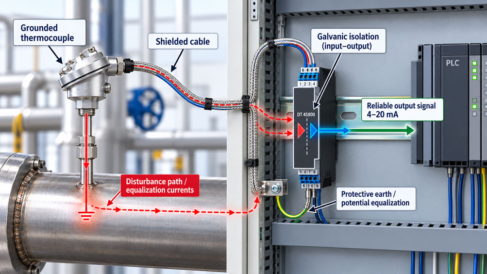
A Type K thermocouple measures the temperature of a heated pipeline. When the plant is at a standstill, the temperature transmitter displays stable and plausible readings. As soon as a variable frequency drive is switched on, the temperature indication begins to fluctuate. Sudden changes sometimes occur even though the actual process temperature has barely changed. Replacing the thermocouple does not resolve the problem.
The cause may lie in the electrical connection between the thermocouple measuring junction and the metallic sheath. In a grounded thermocouple, the measuring junction is electrically connected to the sheath. If the process connection establishes a connection to the machine body or protective equipotential bonding system, the thermocouple signal may be at a different electrical potential from the transmitter input or connected controller.
The actual thermocouple signal is only a few millivolts. Even relatively small coupled differential voltages can therefore cause significant temperature measurement errors. Common-mode interference, unsuitable shield connections, missing galvanic isolation or an impermissible connection between sensor ground and controller ground can also affect the measurement.
A reliable solution is not to disconnect all shields or grounding connections as a general rule. The decisive factors are the electrical design of the measuring junction, the actual equipotential bonding arrangement, the input characteristics of the temperature transmitter and the correct routing of the sensor cable.
This technical article explains the differences between grounded and ungrounded thermocouples, the causes of equalising currents and the selection of suitable galvanically isolated temperature transmitters. It shows how shielding, cold junction compensation, mechanical installation and signal transmission interact and describes a systematic procedure for diagnosing and commissioning temperature measurement points susceptible to interference.
Table of Contents
- Define the Measurement Task and Electrical Operating Conditions
- Understand the Thermocouple Signal and Its Susceptibility to Interference
- Distinguish Grounded, Ungrounded and Exposed Thermocouple Junctions
- Correctly Evaluate Ground Potentials Between the Process and Controller
- Identify Equalising Currents and Common-Mode Interference as Possible Fault Causes
- Distinguish Galvanic Input Isolation and Different Isolation Concepts
- Select Suitable Head-Mounted and DIN-Rail Temperature Transmitters
- Implement Thermocouple Cable Shielding Correctly
- Maintain Protective Earth and Equipotential Bonding Safely
- Select Suitable Thermocouple, Compensating and Extension Cables
- Consider Cold Junction Compensation and Terminal Head Temperature
- Evaluate Sensor Design, Installation and Heat Transfer Correctly
- Calculation Example: How Small Interference Voltages Cause Temperature Errors
- Convert Thermocouple Signals into Interference-Resistant 4–20 mA Signals
- Coordinate Filtering, Damping and Measurement Dynamics
- Operate Multiple Grounded Thermocouples on One Measurement System
- Investigate Sensor Connections, Isolation and Signal Paths Separately
- Consider Electrical Safety, EMC and Explosion Protection
- Check Calibration, Sensor Break Detection and Cold Junction Compensation
- Perform a Systematic Testing and Commissioning Procedure
- Diagnose Typical Fault Patterns and Misinterpretations
- Suitable Temperature Transmitters and Thermocouples from ICS Schneider
- Conclusion: Integrate Grounded Thermocouples Correctly from an Electrical and Measurement Perspective
- Frequently Asked Questions About Grounded Thermocouples and Galvanic Isolation
1. Define the Measurement Task and Electrical Operating Conditions
Thermocouples are used in many industrial applications, including heated pipelines, reactors, furnaces, extruders, heat exchangers and machine components.
The measurement point may be located in a different electrical environment from the downstream controller. Different ground potentials and electromagnetic interference are particularly possible in large installations, systems with variable frequency drives, electrical heating systems and machines distributed over large distances.
Before selecting the temperature transmitter, the complete measurement chain should therefore be considered.
This typically consists of the thermocouple measuring junction, metallic sheath or thermowell, process connection, sensor cable, temperature transmitter and downstream evaluation device.
One decisive factor is the electrical configuration of the measuring junction. Is the thermocouple junction electrically connected to the sheath, or is it electrically insulated from it?
It is equally important to determine whether the sheath is conductively connected to the machine body, pipeline or protective equipotential bonding system through the process connection.
The electrical reference potential of the measuring junction may already be determined by the mechanical installation.
It is also necessary to establish whether the transmitter provides galvanic isolation between the sensor input and the output or power supply.
For multiple measurement channels, it must additionally be checked whether the channels are electrically isolated from each other. Isolation between the sensor side and the output does not automatically mean that several sensor inputs are independently isolated.
Reliable design therefore requires the sensor type, measuring range, installation conditions, process potential, cable routing, interference environment and actual electrical isolation to be considered together.
2. Understand the Thermocouple Signal and Its Susceptibility to Interference
A thermocouple consists of two different metallic conductors electrically connected at the measuring junction.
The thermoelectric effect generates a voltage that depends on the materials used and the temperature distribution along the conductors.
For correct temperature determination, the measured thermoelectric voltage must be evaluated together with the reference junction temperature.
The relationship between temperature and thermoelectric voltage is not generally linear. Standardised thermocouple types are described by corresponding characteristic curves or reference functions.
IEC 60584-1 specifies these characteristics and tolerances for standardised thermocouples.
The low signal level is particularly important. Near room temperature, a Type K thermocouple has a sensitivity of approximately 41 µV/K.
A temperature change of 1 K therefore corresponds to a change in thermoelectric voltage of only approximately 0.041 mV in this temperature range.
By comparison, electrical interference voltages occurring in an industrial installation may be considerably higher than the actual thermocouple signal.
A suitable temperature transmitter therefore requires a sensitive differential input with appropriate common-mode rejection, measurement filtering and cold junction compensation.
However, this high sensitivity also means that wiring errors, additional thermoelectric junctions and coupled interference must be considered.
With a grounded thermocouple in particular, the electrical connection to the process installation can also influence the sensor’s reference potential.
3. Distinguish Grounded, Ungrounded and Exposed Thermocouple Junctions
Thermocouples differ not only in their material type but also in the mechanical and electrical design of their measuring junction.
In mineral-insulated sheathed thermocouples, the thermoelement conductors are located inside a metallic sheath. Compacted mineral insulation electrically separates the conductors from the sheath over most of their length.
Different configurations are possible at the measuring tip.
| Configuration | Electrical Connection | Typical Characteristics | Important Consideration |
|---|---|---|---|
| Grounded junction | Thermocouple measuring junction electrically connected to the metallic sheath | Often good thermal contact and fast response with otherwise comparable construction | Process potential and electrical interference can affect the thermocouple conductors |
| Ungrounded junction | Measuring junction electrically insulated from the metallic sheath | Reduced direct electrical coupling to the process | Insulation condition, heat transfer and input circuitry must be considered |
| Exposed junction | Measuring junction located outside a closed protective sheath | Potentially very fast thermal response depending on construction | Reduced mechanical and chemical protection; possible direct contact with the medium |
In a grounded junction configuration, the measuring junction is electrically connected to the sheath within the sensor assembly. However, this does not necessarily mean that the sheath is reliably connected to protective earth in every installation.
Whether a connection to the plant potential actually exists depends on the mechanical installation and electrical connection of the sheath or thermowell.
In an ungrounded junction, there is no direct conductive connection between the thermoelement conductors and the sheath. Nevertheless, interference can still be transferred through parasitic capacitances or damaged insulation.
Electrical insulation also does not automatically eliminate all other sources of temperature measurement error.
Selection therefore requires a balance between thermal response, mechanical robustness, process resistance and electrical interference immunity.
It is also important to recognise that a metallic thermowell assembly does not automatically prove that the actual thermocouple junction is grounded. The electrical configuration of the measuring insert must be established from the specific order configuration.
4. Correctly Evaluate Ground Potentials Between the Process and Controller
Potential differences can occur between different conductive structural components in industrial installations.
Such differences may result from high operating currents, inadequate equipotential bonding connections, switching operations or electromagnetic coupling.
A grounded thermocouple may be connected to such a plant potential through its metallic sheath and process connection.
If the thermocouple signal is routed over a longer cable to a control cabinet, the transmitter input may have a different electrical reference from the process installation.
This potential difference can become problematic if the measuring input is not adequately designed for it.
An important parameter is common-mode voltage. In simplified terms, this describes the common electrical potential component of both thermocouple conductors relative to the reference potential of the measuring input.
A differential measuring input is primarily intended to detect the voltage difference between the two thermocouple conductors.
However, the presence of a common-mode voltage does not automatically produce a temperature error of the same magnitude. Measurement can remain correct as long as the input operates within its permissible common-mode range and common-mode rejection is sufficient.
Problems arise particularly when the permissible input limits are exceeded or interference is converted into a differential voltage through actual asymmetries and coupling paths.
The measurement point should therefore be evaluated not only under ideal laboratory conditions but also under the actual electrical operating conditions of the installation.
5. Identify Equalising Currents and Common-Mode Interference as Possible Fault Causes
Equalising currents can occur when two electrically connected points have different potentials.
In an industrial temperature measurement chain, such currents may flow through additional ground or shield connections, for example.
An unintended connection between a grounded thermocouple conductor and another equipment ground is particularly problematic if the two points have different potentials.
This can create an unwanted current path.
Cable shielding may also be affected. If a shield is conductively connected at both ends, an equalising current may flow through the shield under certain conditions.
This shield current is not automatically equivalent to a current flowing through the thermocouple conductors. However, it can interfere with the measuring cable through electromagnetic coupling or common impedance coupling.
High-frequency disturbances can occur particularly near variable frequency drives, motor cables and switched-mode power electronics.
Unsuitable shielding or poor cable routing can cause part of an existing common-mode disturbance to become effective as a differential signal.
The thermocouple signal may then fluctuate, develop an offset or temporarily fail under certain operating conditions.
Typical observations include temperature readings changing when a motor starts, periodic interference at the mains frequency or individual measurement jumps when high-power loads are switched.
These symptoms are indications but not definitive proof of equalising currents.
Similar fault patterns may also result from a defective sensor cable, contact problems, unsuitable cold junction compensation or incorrect configuration.
Reliable diagnosis therefore requires investigation of the actual electrical connections and interference paths.
6. Distinguish Galvanic Input Isolation and Different Isolation Concepts
Galvanic isolation interrupts the direct conductive connection between the circuits that are electrically separated.
In a temperature transmitter, the thermocouple signal is acquired and processed on the input side and then transferred across a suitable isolation barrier to the output or supply side.
This can prevent a direct equalising current from flowing between the thermocouple circuit and the downstream controller through the transmitter.
However, the actual protective effect depends on the instrument design and its specified characteristics.
Different isolation concepts must be distinguished in particular.
| Configuration | Electrical Isolation | Typical Application | Important Limitation |
|---|---|---|---|
| Non-isolated transmitter | No galvanic input-to-output isolation | Simple temperature measurement points with suitable potential conditions | Additional ground connections and potential differences require particular consideration |
| Galvanically isolated two-wire transmitter | Sensor input isolated from the output/current loop side | Grounded thermocouples with 4–20 mA transmission | Permissible input voltage, isolation and other operating limits must still be observed |
| Three-way isolated transmitter | Isolation between sensor input, signal output and auxiliary power supply | Control cabinet applications involving different electrical potentials | Working voltage and safety requirements must match the specific application |
| Multi-channel transmitter | Different isolation arrangements between channels and outputs depending on design | Multiple thermocouples with common evaluation | Input-to-output isolation does not automatically mean channel-to-channel isolation |
When selecting a transmitter, it is particularly important to verify that the sensor input is actually galvanically isolated from the output side.
The specification “galvanically isolated” should be clearly attributable to the relevant circuits using the data sheet or internal block diagram.
The isolation test voltage must also be interpreted correctly. A value such as 1,500 V AC for a specified test duration describes a defined insulation test and is not automatically the permissible continuous working voltage between the circuits.
For safety-related electrical requirements, the permissible working voltage, insulation class, overvoltage category and additional manufacturer specifications must be considered.
One suitable example from the ICS product range is the DT 45800 thermocouple transmitter. It provides three-way isolation between the sensor input, output and auxiliary power supply.
Such isolation can prevent equalising currents from flowing through the transmitter electronics. However, it does not replace mandatory protective equipotential bonding or correct shielding and cable routing.
7. Select Suitable Head-Mounted and DIN-Rail Temperature Transmitters
Temperature transmitters can be installed directly in the connection head of a thermometer, in a field enclosure or on a DIN rail inside a control cabinet.
The appropriate design depends on both environmental conditions and the electrical measurement task.
A head-mounted transmitter offers the advantage that the sensitive thermoelectric voltage only needs to be transmitted over a relatively short distance.
The temperature is converted into a more robust output signal, such as 4–20 mA, close to the sensor.
The longer connection to the controller then no longer carries the original microvolt or millivolt signal.
This can be beneficial in industrial installations with high levels of interference.
However, a head-mounted transmitter is often located closer to hot process components. The permissible ambient temperature of the transmitter and the thermal conditions inside the connection head must therefore be considered.
A large temperature gradient within the terminal head can particularly affect cold junction compensation.
With a DIN-rail transmitter, the evaluation electronics are located inside the control cabinet. This provides better access for configuration and often more favourable ambient temperatures.
However, the sensitive thermocouple signal must be transmitted over a longer distance. Suitable thermocouple or compensating cables and an appropriate EMC installation are therefore required.
The choice between head-mounted and DIN-rail transmitters must therefore consider cable length, environmental conditions, required galvanic isolation and maintenance accessibility together.
Both designs may provide input-to-output isolation. The physical mounting style alone does not indicate whether galvanic isolation is present.
8. Implement Thermocouple Cable Shielding Correctly
A shielded thermocouple cable can reduce the coupling of electromagnetic interference.
For measurement points susceptible to interference, twisted thermocouple conductors or suitable twisted compensating cable pairs with a common shield are frequently used.
Under suitable conditions, the twisted conductor arrangement reduces the effective loop area available for magnetic interference coupling.
The shield is particularly effective against certain electric-field and high-frequency disturbances. Its performance depends on cable construction and correct termination.
With a grounded thermocouple, particular care must be taken to ensure that the shield does not unintentionally create a second conductive connection between the thermocouple measuring junction and the measuring input.
One commonly used solution is to terminate the cable shield at a defined point, for example on the evaluation side, in accordance with the intended EMC and grounding concept.
Single-ended shield termination can prevent low-frequency equalising currents from flowing through the shield when potential differences exist between the field and control cabinet.
However, this solution is not optimal for every electromagnetic environment.
Where pronounced high-frequency interference is present, shielding connected at both ends with the lowest possible impedance may be appropriate, provided that effective equipotential bonding is available and the overall EMC concept supports this arrangement.
The suitable solution depends on the frequency spectrum, cable construction, plant potentials and specific manufacturer instructions.
A general rule requiring all thermocouple shields to be connected exclusively at one end or always at both ends is therefore technically insufficient.
The shield must also not be used as a substitute for a required protective earth conductor or as an ordinary signal return conductor.
During termination, care must be taken to prevent unintended contact between the shield and a thermocouple conductor.
Cable routing is also relevant. Thermocouple cables should be routed with suitable separation from motor cables, inverter cables and other high-interference power cables in accordance with the EMC concept.
9. Maintain Protective Earth and Equipotential Bonding Safely
When troubleshooting grounded thermocouples, attempts are sometimes made to eliminate a suspected ground loop by disconnecting an earthing connection.
Such action can create serious electrical safety hazards.
Protective earth and necessary protective equipotential bonding connections are intended to limit dangerous touch voltages and other electrical risks.
They must not be disconnected simply to improve a temperature reading.
The technical solution must instead be implemented at the appropriate signal or isolation level.
For example, a galvanically isolated temperature transmitter can interrupt the direct conductive path between a grounded sensor junction and the downstream controller.
This allows the necessary protective equipotential bonding of the installation to remain intact while the signal processing is electrically isolated.
If shielding has been installed incorrectly, its termination may also need to be modified.
Required protective and EMC connections must remain effective in this case as well.
In installations with variable frequency drives, suitable low-impedance equipotential bonding connections and the EMC measures specified by the manufacturer are particularly important.
An individual equipotential bonding conductor that appears to cause interference must not be considered unnecessary without proper technical assessment.
Safe electrical installation and the prevention of measurement interference must therefore be treated as related requirements.
10. Select Suitable Thermocouple, Compensating and Extension Cables
The electrical cable between the thermocouple and temperature transmitter is part of the thermoelectric measurement chain.
It must not be selected solely on the basis of conductor cross-section or electrical conductivity.
Suitable thermocouple, extension or compensating cables are used for thermocouple measurements.
Extension cables have thermoelectric properties matching the corresponding thermocouple type within their specified temperature range.
Compensating cables, on the other hand, use defined substitute materials whose thermoelectric properties sufficiently correspond to the associated thermocouple within the specified operating range.
IEC 60584-3:2021 addresses the requirements, tolerances and identification of corresponding extension and compensating cables.
For correct measurement, the cable type must match the thermocouple type.
Correct polarity is also important. Reversed thermocouple conductors can cause implausible readings and incorrect temperature behaviour.
The use of ordinary copper cables requires particular attention.
If a thermocouple is extended using copper cable without suitable signal conversion, additional thermoelectric junctions may be introduced. The measurement must then correctly account for the temperatures of the relevant transitions.
Installing a temperature transmitter directly at the sensor can simplify this problem. After conversion to a 4–20 mA signal, a suitable standard signal cable can be used.
However, suitable thermocouple conductors and connection materials must be used before the actual thermocouple input.
Connectors and terminals must also be appropriate for the application. Uncontrolled temperature differences at transition points can cause additional measurement errors.
11. Consider Cold Junction Compensation and Terminal Head Temperature
A thermocouple does not measure absolute temperature directly. The measured thermoelectric voltage is related to the temperature difference or thermoelectric relationship between the measuring junction and the reference junction.
For a correct temperature indication, the reference junction temperature must be known or appropriately compensated.
Modern temperature transmitters frequently provide internal cold junction compensation (CJC) for this purpose.
This measures or takes into account the temperature in the area of the designated electrical connection point.
Thermal design is particularly important for head-mounted transmitters. Strong heating from the process fitting or heat applied predominantly from one side can cause uneven temperatures within the connection head.
If the actual temperatures at the thermoelectric conductor transitions are not adequately represented by the internal reference junction measurement, an additional error may occur.
Thermal influences can also be relevant to DIN-rail transmitters. For example, uneven heating from neighbouring power components or warm control cabinet areas may affect the terminal region.
Cold junction compensation must therefore be evaluated independently of galvanic isolation.
A galvanically isolated transmitter may be suitable for preventing equalising currents but still indicate an incorrect temperature if cold junction compensation is inadequate.
Conversely, excellent cold junction compensation cannot automatically eliminate existing electrical common-mode problems.
During commissioning, both the electrical and thermal characteristics of the transmitter must therefore be verified.
12. Evaluate Sensor Design, Installation and Heat Transfer Correctly
The accuracy of an industrial temperature measurement point depends on more than the thermocouple and its transmitter.
The mechanical installation also influences which temperature is actually measured.
For example, a thermocouple may measure the temperature of a medium inside a pipeline. To achieve this, heat must be transferred sufficiently effectively from the medium to the thermocouple measuring junction.
Thermowells, measuring inserts and mechanical contact surfaces introduce additional thermal resistances.
Good contact at the intended measuring position is particularly important for replaceable measuring inserts.
In suitable designs, a spring-loaded measuring insert ensures that the tip is pressed against the bottom of the thermowell with a defined force.
Insufficient contact can increase the response time and, under certain conditions, cause measurement deviations.
Insertion length and heat conduction along the fitting may also be relevant.
If a probe is installed with insufficient insertion depth, heat transfer to the surrounding environment or pipe wall can have a greater influence on the result.
Selecting a grounded junction can improve thermal response because there is direct metallic contact between the measuring junction and the sheath.
However, the magnitude of this advantage depends on the complete sensor design, sheath thickness, thermowell and actual installation conditions.
A grounded thermocouple should therefore not be selected solely on the basis of a general statement about response time.
For demanding measurement applications, thermal characteristics, electrical isolation, process resistance and mechanical requirements must be evaluated together.
13. Calculation Example: How Small Interference Voltages Cause Temperature Errors
A simplified example demonstrates the sensitivity of a Type K thermocouple to additional differential voltages.
Near room temperature, the thermoelectric sensitivity of Type K is approximately 41 µV/K.
Assume that unsuitable wiring or electromagnetic coupling produces an additional effective differential voltage of 0.205 mV at the measuring input.
This corresponds to:
UStörung = 0.205 mV = 205 µV
The approximate resulting temperature deviation can be estimated using:
ΔT ≈ UStörung / S
Here, S denotes the local thermoelectric sensitivity.
With S = 41 µV/K:
ΔT ≈ 205 µV / (41 µV/K) ≈ 5 K
An additional effective differential voltage of only 0.205 mV can therefore cause a temperature error of approximately 5 K in the temperature range considered.
Under the same simplified assumption, an additional differential voltage of 0.820 mV would already produce an error of approximately 20 K.
These values demonstrate the high sensitivity of thermocouple measurements.
The calculation expressly applies only to an interference voltage that actually becomes effective as a differential voltage at the input.
A pure common-mode voltage must not automatically be treated as an equivalent differential voltage. A suitably designed differential or galvanically isolated measuring input can largely reject common-mode components within its specified limits.
Furthermore, thermoelectric sensitivity is not constant across the entire temperature range. Accurate calculations must use the characteristic curve of the relevant thermocouple type.
The example is therefore intended to illustrate susceptibility to interference and does not constitute a complete measurement uncertainty calculation.
14. Convert Thermocouple Signals into Interference-Resistant 4–20 mA Signals
A proven method of industrial signal transmission is to convert the sensitive thermocouple signal into a standardised current signal as close to the sensor as possible.
In 4–20 mA transmission, the measured temperature range is assigned to a defined current range.
The transmitter evaluates the thermoelectric voltage, performs cold junction compensation and applies the necessary characteristic curve linearisation.
In appropriately designed devices, galvanic isolation is also provided between the thermocouple input and current loop.
For an example temperature range of 0 … 400 °C, linear current scaling gives:
I = 4 mA + 16 mA · (T − 0 °C) / 400 K
At a temperature of 200 °C:
I = 4 mA + 16 mA · 200 / 400 = 12 mA
The PLC input therefore receives a current value proportional to temperature rather than having to evaluate the very small thermoelectric voltage itself.
The current signal is more resistant to certain cable resistance effects and interference than direct transmission of the unfiltered millivolt signal.
However, a 4–20 mA current loop is not fundamentally immune to all electromagnetic disturbances or wiring errors.
The available supply voltage, permissible load resistance, loop wiring and input characteristics of the controller must be considered.
It is particularly important that galvanic isolation is actually provided by the temperature transmitter being used.
A two-wire transmitter is not automatically galvanically isolated. Similarly, a 4–20 mA output alone does not mean that the sensor side is electrically isolated from the evaluation or supply circuit.
Only the specific manufacturer documentation confirms the available isolation function.
15. Coordinate Filtering, Damping and Measurement Dynamics
Temperature transmitters frequently provide filtering and damping functions to smooth fluctuating input signals.
Filtering can reduce 50 or 60 Hz mains-frequency interference and other electromagnetic disturbances, for example.
An adjustable time constant may also be used to suppress short-duration signal changes.
However, excessive damping can conceal actual dynamic temperature behaviour.
If the temperature of an installation rises very quickly, the measuring system must respond sufficiently fast to capture the relevant change.
For slow temperature monitoring in a large vessel, stronger damping may be appropriate.
However, fast temperature control or overtemperature monitoring may impose different requirements.
It is particularly important not to confuse filtering with elimination of the cause of interference.
If a grounded measuring junction is exposed to substantial equalising or interference currents because of unsuitable wiring, increasing the damping may make the fluctuations less visible.
However, the electrical cause remains present.
Excessively high common-mode voltages or overloaded inputs also cannot be reliably corrected through simple software filtering.
The appropriate sequence is therefore to check the electrical signal routing and isolation first and then configure filtering according to the actual measurement dynamics required.
16. Operate Multiple Grounded Thermocouples on One Measurement System
In larger industrial installations, several thermocouples are frequently installed on different pipelines, vessels or machine components.
These individual measuring junctions may be at different electrical potentials.
This becomes particularly relevant with grounded thermocouples when several sensors are connected to a common multi-channel measuring device.
For example, a multi-channel measurement system may have a shared internal reference circuit.
If the sensor inputs are not galvanically isolated from one another, different sensor potentials may influence each other or exceed the permissible input limits.
A device with galvanic isolation from the output side does not necessarily provide galvanic isolation between all individual input channels.
The isolation arrangement must therefore be checked using the block diagram or technical specifications of the specific measuring module.
One possible solution is to evaluate each grounded thermocouple through its own galvanically isolated temperature transmitter.
Another option is to use a multi-channel measurement system with explicitly specified channel-to-channel isolation.
With instruments having two sensor inputs, for example for sensor redundancy or drift detection, independent isolation between the two sensor connections must not be assumed without corresponding manufacturer specifications.
For differential temperature measurements, it is also important that both values are acquired under the intended electrical and thermal conditions.
The overall system architecture must therefore account for the different potentials of the individual measuring junctions when selecting the evaluation device.
17. Investigate Sensor Connections, Isolation and Signal Paths Separately
Systematic troubleshooting begins by distinguishing between sensor faults, electrical interference and incorrect signal processing.
Simply replacing the thermocouple is not necessarily effective if the underlying cause lies within the electrical measuring circuit.
The first step is to determine which electrical junction configuration is actually installed.
In a grounded thermocouple, the measuring junction is conductively connected to the metallic sheath by design.
In an ungrounded configuration, this connection should not exist under the specified test conditions.
However, insulation condition must not be checked using an unsuitable high test voltage while sensitive electronics remain connected.
In particular, insulation testers intended for general electrical installations can damage sensitive temperature transmitters or Ex input circuits.
Suitable test procedures, permissible test voltages and required disconnection measures must be determined from the manufacturer documentation.
The next step is to investigate the cable between the thermocouple and transmitter. This includes correct polarity, cable type, terminals and shield connections.
The actual electrical connection between the process installation and control cabinet is also relevant.
Measurements of potential differences in electrical installations must only be performed by appropriately qualified personnel under suitable safe conditions.
It can be particularly useful to compare temperature readings during different normal operating states of the installation, for example with the drive switched on and off.
If the indication changes only when a variable frequency drive is operating, this suggests possible electromagnetic interference.
This relationship should then be investigated using suitable measurements along the signal path.
A stable indication after disconnecting a shield does not automatically prove that disconnecting it is the correct or safe permanent solution.
18. Consider Electrical Safety, EMC and Explosion Protection
Measurement accuracy and electrical safety must be considered separately when designing systems with grounded thermocouples.
Galvanic isolation can help prevent unwanted equalising currents and the transfer of interference voltages between circuits.
However, the isolation must be designed for the actual voltages occurring and the intended operating conditions.
A specified isolation test voltage must not automatically be interpreted as the permissible continuous voltage between input and output circuits.
The respective manufacturer’s specifications concerning insulation type, permissible working voltage and electrical safety are decisive.
Electromagnetic compatibility must also be considered.
DIN EN IEC 61326-1 addresses general EMC requirements for electrical measurement, control and laboratory equipment.
Additional requirements or corresponding product-specific standards may apply depending on the instrument and application.
However, the EMC conformity of a temperature transmitter does not automatically mean that every possible cable routing arrangement in an industrial installation will operate without interference.
The actual wiring, shielding and equipotential bonding arrangement remain decisive.
Additional requirements apply in potentially explosive atmospheres.
A thermocouple, temperature transmitter and associated wiring must be suitable for the intended type of protection and relevant approval conditions.
For intrinsically safe circuits, the corresponding electrical limits, permissible connections and required verification of intrinsic safety must be considered.
Galvanic isolation alone does not replace an appropriate Ex approval.
The grounding and shielding of Ex measurement circuits must also comply with the requirements applicable to the specific system.
Protective earth conductors and safety-related equipotential bonding connections must not be disabled to eliminate interference.
19. Check Calibration, Sensor Break Detection and Cold Junction Compensation
Reliable temperature measurement requires not only a suitable sensor but also correct operation of the temperature transmitter.
Different parts of the measurement chain can be investigated during calibration or functional testing.
For example, an electrical test of the temperature transmitter can be performed using a suitable thermocouple or millivolt simulator.
This provides a defined thermoelectric voltage or a correspondingly simulated thermocouple value.
For correct testing, the cold junction compensation used must be taken into account.
Depending on the test method, reference junction compensation may be performed by the simulator or by the temperature transmitter.
An incorrect combination of these settings can produce a substantial measurement error.
Electrical testing of the transmitter also does not automatically confirm the thermal accuracy of the complete installed thermocouple.
For complete verification of the temperature measurement chain, the sensor and installation conditions must also be considered according to the intended test procedure.
Many modern temperature transmitters also provide sensor break detection.
If a thermocouple conductor is interrupted, the transmitter can generate a corresponding fault signal.
With galvanically isolated two-wire transmitters, fault signalling is often provided using a defined current outside the normal measuring range.
The actual current values, fault signal direction and diagnostic functions available depend on the instrument and its configuration.
The PLC must therefore be configured to distinguish between valid temperature measurements and sensor or instrument faults.
Certain devices can also monitor sensor lead resistance, insulation condition or other diagnostic parameters.
However, a grounded thermocouple must not be treated as an ordinary ungrounded sensor for such functions without checking the instrument characteristics.
The diagnostic and insulation monitoring functions must be suitable for the specific electrical junction configuration.
20. Perform a Systematic Testing and Commissioning Procedure
Commissioning a temperature measurement point with a grounded thermocouple should consider mechanical, thermal and electrical operating conditions together.
The following procedure describes a general test sequence for appropriately qualified personnel. Actual implementation depends on manufacturer documentation and the safety requirements of the installation.
- Identify the measurement point: Document the thermocouple type, measuring range, installation location, process conditions and intended measurement task.
- Check the junction configuration: Determine whether the thermocouple measuring junction is grounded, ungrounded or exposed.
- Inspect mechanical installation: Evaluate the sheath, thermowell, insertion length, process connection and intended thermal contact.
- Identify the electrical reference potential: Check the intended connection between the sensor, machine body and protective equipotential bonding system using the installation documentation.
- Identify the temperature transmitter: Document the model, firmware or configuration, sensor input, output signal and power supply.
- Check galvanic isolation: Evaluate input-to-output isolation and, where several inputs are present, any channel-to-channel isolation using the device documentation.
- Compare permissible input conditions: Consider possible common-mode voltages and permissible electrical operating limits.
- Inspect the thermocouple cable: Verify the suitable extension or compensating cable, polarity, conductor condition and terminal connections.
- Investigate shielding: Compare shield termination and cable routing with the intended EMC and equipotential bonding concept.
- Check the cold junction: Consider internal or external compensation, connection head temperature and possible temperature gradients.
- Configure the transmitter: Define the thermocouple type, temperature range, linearisation, output signal and damping where applicable.
- Perform electrical signal testing: Check the intended input or output using suitable test equipment and correctly configured cold junction compensation.
- Test sensor break detection: Verify the intended diagnostic function according to the manufacturer procedure and compare it with PLC evaluation.
- Observe the measurement point during normal operation: Record the temperature indication and electrical interference conditions under representative plant operating states.
- Evaluate measurement dynamics: Check whether sensor response time and transmitter damping are suitable for the process task.
- Check measurement plausibility: Compare temperature readings with suitable reference information and the actual thermal process condition.
- Perform necessary corrections: Correct wiring, shielding or configuration errors only after proper technical evaluation.
- Complete documentation: Record sensor and transmitter data, grounding and shielding concept, measured values, test results and approval.
It is particularly important not to immediately interpret a temperature-dependent measurement deviation as an electrical fault.
Poor heat transfer can cause deviations similar to those resulting from incorrect cold junction compensation.
Conversely, good agreement at a single test temperature must not be treated as proof that the measuring point will operate without interference under all electrical operating conditions.
Reliable commissioning therefore requires both thermal and electrical characteristics to be evaluated under representative conditions.
21. Diagnose Typical Fault Patterns and Misinterpretations
When troubleshooting grounded thermocouples, it is particularly important to distinguish between electrical interference, sensor problems and temperature measurement errors.
| Observation | Possible Cause | Suitable Check |
|---|---|---|
| Temperature indication fluctuates when a variable frequency drive is switched on | Electromagnetic coupling, common-mode interference or unsuitable shielding | Investigate cable routing, reference potential, shield termination and input isolation |
| Temperature measurement is stable in the laboratory but unstable in the installation | Different ground potentials or other electrical environmental conditions | Check the measurement point under representative plant operating conditions |
| Temperature reading has a constant offset | Cold junction error, additional effective thermoelectric voltage or incorrect configuration | Check the reference junction, thermocouple type, connections and transmitter |
| Several temperature channels influence each other | Insufficient channel-to-channel isolation or shared electrical reference points | Evaluate the isolation concept of the multi-channel device and sensor potentials |
| Measured value jumps when heaters or contactors are switched | Interference pulses through signal or supply cables | Investigate switching operations, signal routing and filtering |
| Temperature indication changes when the connecting cable is touched or moved | Contact problem, damaged cable or unsuitable shielding | Inspect terminals and cable under safe conditions |
| Transmitter reports a sensor break although the thermocouple is connected | Interrupted conductor, poor terminal connection or unsuitable diagnostic conditions | Check cable condition and sensor break detection according to the manufacturer’s procedure |
| Temperature measurement responds unusually slowly | Poor thermal contact, large thermowell or excessive damping | Evaluate installation, heat transfer and configured time constants |
| Thermocouple and reference thermometer agree only at certain temperatures | Incorrect sensor type, thermocouple cable, cold junction or characteristic curve evaluation | Check the complete thermal and electrical measurement chain |
| Signal becomes stable after changing to an isolated transmitter | Possible previous influence of potential differences or ground coupling | Evaluate the electrical cause using the actual isolation and shielding concept |
| 4–20 mA signal is stable, but the PLC displays an incorrect temperature | Scaling error or unsuitable PLC input configuration | Compare the transmitter measuring range with PLC scaling |
| Electrical transmitter test is correct, but process measurement remains implausible | Sensor fault, heat transfer problem, cold junction error or installation issue | Investigate the sensor and installation separately from the transmitter |
The table illustrates possible causes and suitable diagnostic approaches but does not replace complete fault diagnosis.
It is particularly important not to confuse electrical interference with thermal measurement deviations prematurely.
Insufficient galvanic isolation can cause measurement problems. However, an incorrectly connected thermocouple or unsuitable cold junction compensation can produce similar symptoms.
The cause must therefore be determined by investigating the complete measurement chain.
22. Suitable Temperature Transmitters and Thermocouples from ICS Schneider
22.1 DT 45800: Thermocouple Transmitter with Three-Way Isolation
The DT 45800 thermocouple transmitter is designed for industrial acquisition and processing of thermocouple signals.
It provides a universal thermocouple input and allows selection from more than 1,800 preconfigured standard measuring ranges.
Configuration is performed using DIP switches or a USB connection with the corresponding DRAGOset programming kit.
One essential feature is galvanic three-way isolation between the sensor input, signal output and auxiliary power supply.
This function is particularly useful for measurement tasks involving different electrical potentials or possible transfer of interference voltages between the measuring point and controller.
The DT 45800 has a slim 6.2 mm housing and is designed for installation on a 35 mm DIN rail.
Depending on configuration, current outputs of 0 … 20 mA or 4 … 20 mA and voltage outputs such as 0 … 5 V and 0 … 10 V are available.
The nominal auxiliary power supply is 24 V DC.
The manufacturer specifies an isolation test voltage of 3 kV AC for the corresponding three-way isolation. The permissible working voltage and requirements for protective separation are specified separately.
The DT 45800 may therefore be a particularly suitable solution for grounded thermocouples requiring control cabinet installation.
The actual permissible potential differences must nevertheless be checked against its isolation and operating specifications.
22.2 IPAQ C330: Galvanically Isolated Head-Mounted Temperature Transmitter
The IPAQ C330 from INOR is a universal digital two-wire temperature transmitter designed for installation in a terminal head.
It supports thermocouple Types B, E, J, K, N, R, S and T, among other suitably specified sensor types.
The transmitter converts the measured temperature into a 4–20 mA output signal.
One essential feature is galvanic isolation between the sensor input and current loop side. An isolation test voltage of 1,500 V AC is specified for the corresponding device configuration.
The IPAQ C330 can be configured via NFC and, with suitable accessories, via Bluetooth.
This makes it suitable for applications in which the sensitive thermoelectric voltage should be processed directly in the connection head.
For a grounded thermocouple measuring junction, galvanic isolation can help prevent an unwanted direct equalising current path to the controller.
During selection, the permissible terminal head temperature, required Ex configuration and actual isolation conditions must be checked.
22.3 IPAQ R330: Galvanically Isolated DIN-Rail Transmitter with NFC
The IPAQ R330 is a universal programmable temperature transmitter for DIN-rail installation.
It supports resistance thermometers, thermocouples and other suitable input signals.
The output signal is 4–20 mA.
The transmitter provides galvanic isolation with a documented isolation test voltage of 1,500 V AC.
The designated software and NFC functions are available for configuration.
The IPAQ R330 is particularly suitable for control cabinet applications in which several separate temperature measurement points are brought together.
With grounded thermocouples, individual galvanically isolated transmitters can help prevent unwanted conductive connections between different sensor potentials and the common controller level.
Suitable thermocouple or compensating cables are still required for the connection between the thermocouple and DIN-rail transmitter.
22.4 WIKA T38: Temperature Transmitter with HART Protocol and Diagnostic Functions
The WIKA T38 is a digital temperature transmitter for industrial process applications.
It is available in head-mounted and DIN-rail versions and supports various thermocouples, resistance thermometers and other suitable sensor signals.
The output is provided as a 4–20 mA current loop with HART communication.
For the WIKA T38, the operating instructions specify an isolation test voltage of 1,500 V AC for 60 seconds between the input and analogue output.
Features include configurable characteristic curve processing, sensor monitoring and various diagnostic functions in accordance with relevant NAMUR recommendations.
Suitable sensor and instrument configurations can also provide functions such as sensor redundancy or drift detection.
The T38 is therefore suitable for demanding temperature measurement points where diagnostic data is required for maintenance and process automation in addition to temperature measurement.
When several grounded thermocouples are connected, the specific electrical isolation between the sensor inputs must be checked against the intended connection configuration.
Documented isolation between the sensor input and analogue output does not automatically demonstrate independent galvanic isolation of every individual sensor input.
22.5 IPAQ-4L: Highly Isolated Temperature and Signal Transmitter
The IPAQ-4L is a universal four-wire transmitter with a separate auxiliary power supply.
It supports thermocouples, resistance thermometers and other electrical measurement quantities.
Depending on configuration, current and voltage outputs such as 4–20 mA and 0–10 V are available.
The manufacturer specifies an isolation test voltage of 4,000 V AC for one minute.
The transmitter also provides sensor monitoring, output simulation and detection of low sensor insulation resistance under the designated measurement conditions.
The IPAQ-4L may therefore be suitable for industrial measurement points with increased requirements for electrical isolation and signal conditioning.
However, the high isolation test voltage must not be interpreted as general approval for a permanently applied potential difference of the same magnitude.
For a grounded thermocouple measuring junction, the permissible working voltage, isolation concept and suitability of the actual sensor monitoring functions must be checked.
22.6 WIKA TC10-H: Industrial Thermocouple for Direct Process Installation
The WIKA TC10-H is an industrial thermocouple without an integrated thermowell.
It features a mineral-insulated sheathed measuring cable and is designed for suitable direct process installation.
The instrument is suitable, for example, for machine components, pipelines and vessels.
Depending on configuration, the documented sensor range extends from -40 … +1,200 °C.
Suitable process connections, terminal heads and temperature transmitters can be selected for the specific application.
It is important that the electrical configuration of the measuring junction must be specified separately. The designation TC10-H alone does not automatically mean that the thermocouple has a grounded measuring junction.
For an application susceptible to interference, the required grounded or ungrounded junction configuration, process connection and electrical signal conditioning must therefore be specified together.
Additional thermocouples and suitable transmitters are available from ICS Schneider in the Thermocouples and Temperature Transmitters and Accessories categories.
23. Conclusion: Integrate Grounded Thermocouples Correctly from an Electrical and Measurement Perspective
A grounded thermocouple can offer advantages in response time because of the direct thermal contact between the measuring junction and metallic sheath.
At the same time, the thermocouple junction is electrically connected to the sheath. If a conductive connection to the process installation exists, the measuring signal may therefore be at the potential of the machine body or pipeline.
If potential differences occur between the process installation and evaluation device, the measuring input must be suitable for these conditions.
A galvanically isolated temperature transmitter can prevent a direct conductive connection between the sensor input and output circuitry, thereby reducing the risk of interfering equalising currents flowing through the electronics.
The actual isolation structure and specified operating limits of the device are decisive.
Shielding must also be adapted to the specific installation. Suitable shield termination can reduce electromagnetic interference but must not create uncontrolled additional current paths.
Protective earth conductors and necessary equipotential bonding connections must remain fully effective.
However, electrical interference immunity is only one aspect of overall measurement quality. Cold junction compensation, sensor type, cable material, insertion length and heat transfer also influence the temperature measurement result.
A reliable temperature measurement point therefore results from the coordinated interaction of the sensor, installation, cable, isolation, transmitter and evaluation system.
Identify the junction configuration → Evaluate process potential and signal path → Select suitable galvanic input isolation → Coordinate shielding and equipotential bonding → Check thermocouple cable and cold junction → Configure the temperature transmitter → Test the electrical and thermal measurement chain → Verify measurement under realistic plant operating conditions → Document the results
The most important practical principle is therefore: A grounded thermocouple is not inherently unsuitable for industrial installations with high interference levels. The decisive factor is that the associated temperature transmitter and complete signal routing are correctly designed for the existing electrical potentials and electromagnetic conditions.
24. Frequently Asked Questions About Grounded Thermocouples and Galvanic Isolation
24.1 What Is a Grounded Thermocouple?
In a grounded thermocouple, the thermoelectric measuring junction is electrically connected to the metallic protective sheath. Whether this also establishes a connection to the plant’s protective equipotential bonding system depends on the actual mechanical and electrical installation.
24.2 What Is the Difference Between a Grounded and an Ungrounded Thermocouple?
In a grounded thermocouple, an electrical connection exists between the measuring junction and the sheath. In an ungrounded configuration, the thermoelement conductors are electrically insulated from the sheath. Both designs differ in thermal behaviour and possible electrical interference coupling.
24.3 Why Can Grounded Thermocouples Cause Measurement Errors?
Common-mode voltages and interference can affect the sensor circuit through its conductive connection to the process installation. If the measuring input or wiring is unsuitable, measurement errors may occur. A correctly designed isolated measuring input can significantly reduce these influences.
24.4 Does Every Grounded Thermocouple Require a Galvanically Isolated Transmitter?
Not necessarily. The decisive factors are the actual potential conditions, input characteristics and safety requirements. However, suitable galvanic isolation is frequently particularly beneficial in industrial installations with different ground potentials or pronounced electromagnetic interference.
24.5 What Does Galvanic Input Isolation Mean in a Temperature Transmitter?
It means that there is no direct conductive connection between the thermocouple input circuit and the correspondingly isolated output or supply circuit. The measurement signal is transferred across a suitable isolation barrier.
24.6 Is a 4–20 mA Temperature Transmitter Automatically Galvanically Isolated?
No. Non-isolated temperature transmitters can also provide a 4–20 mA signal. Galvanic isolation must be explicitly confirmed by the technical specifications or block diagram of the specific device configuration.
24.7 What Is the Advantage of Three-Way Isolation?
With three-way isolation, the sensor input, signal output and auxiliary power supply are galvanically isolated from each other according to the device specification. This can prevent unwanted direct conductive connections between the different circuits. One example is the DT 45800 from ICS Schneider.
24.8 Does a Thermocouple Cable Shield Have to Be Connected at One End Only?
Single-ended shield termination is suitable for many measurement applications to prevent low-frequency equalising currents from flowing through the shield. For particular high-frequency EMC requirements, termination at both ends may also be appropriate. The relevant factors are equipotential bonding, the interference environment and manufacturer instructions.
24.9 Can I Disconnect Protective Earth if the Temperature Measurement Is Affected by Interference?
No. Safety-related protective earth conductors and equipotential bonding connections must not be disconnected to improve a measurement indication. Interference must be eliminated through suitable signal isolation, shielding, cable routing or other appropriate technical measures.
24.10 Can the Sheath of a Grounded Thermocouple Be at a Different Potential from the PLC?
Yes. Potential differences may occur between the process installation and control cabinet. If the thermocouple is conductively connected to the process installation, this can affect the common-mode voltage at the measuring input. The permissible input conditions must therefore be checked.
24.11 Why Is a Thermocouple Signal Particularly Susceptible to Interference?
Thermocouples generate very small voltages. Near room temperature, the sensitivity of a Type K thermocouple is approximately 41 µV/K. Even small additional effective differential voltages can therefore cause measurable temperature errors.
24.12 Which Cable Should I Use for a Type K Thermocouple?
A suitable Type K thermocouple, extension or compensating cable must be used according to the intended temperature conditions. Polarity, identification and the requirements of IEC 60584-3 must be considered. A suitable shielded, twisted construction may be beneficial in areas with high levels of interference.
24.13 What Is Cold Junction Compensation?
Cold junction compensation accounts for the temperature at the designated electrical transition between the thermocouple cable and measuring electronics. Without correct compensation, a reliable absolute measuring temperature cannot be determined from the thermoelectric voltage.
24.14 Can Incorrect Cold Junction Compensation Resemble a Grounding Problem?
Yes. Both faults can produce implausible temperature readings. However, incorrect cold junction compensation causes a different physical effect from electrical common-mode interference. The two causes must therefore be investigated separately.
24.15 Is a Head-Mounted Transmitter Better Than a DIN-Rail Transmitter?
A head-mounted transmitter reduces the transmission distance of the sensitive thermocouple signal and converts it into a more robust standard signal directly at the sensor. A DIN-rail transmitter, on the other hand, offers advantages for centralised installation and maintenance access. The better solution depends on temperature conditions, cable length, interference environment and required galvanic isolation.
24.16 Can I Connect Several Grounded Thermocouples to a Multi-Channel Transmitter?
This is possible if the multi-channel transmitter is suitable for the actual electrical potentials and intended sensor configuration. Common input-to-output isolation does not automatically mean that the individual sensor inputs are galvanically isolated from one another.
24.17 Which Temperature Transmitters from ICS Provide Galvanic Isolation?
The ICS product range includes the DT 45800 with three-way isolation, the INOR IPAQ C330 and IPAQ R330 transmitters, and the WIKA T38, among others. The highly isolated IPAQ-4L is also available for corresponding signal applications. The specific device configuration and permissible isolation conditions must match the application.
24.18 What Information Does ICS Schneider Need for Equipment Selection?
The required information includes the thermocouple type, whether the measuring junction is grounded or ungrounded, the temperature measuring range, installation method and existing process conditions. Cable length, compensating cable type, shielding, electrical potential conditions, possible EMC interference sources and the type of connected controller are also important. Selection of the temperature transmitter additionally requires information about galvanic isolation, permissible working voltage, output signal, power supply, HART communication, diagnostic functions, installation location and any Ex or SIL configurations. For demanding measurement applications, the desired measurement uncertainty, dynamic response and required calibration must also be specified.