


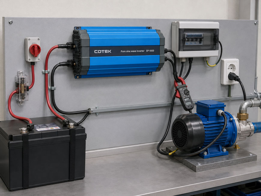
An electric motor with a rated power of 800 W cannot automatically be operated reliably with an inverter rated for 1,000 W continuous power. During startup, the motor may briefly draw several times its normal operating current.
Similar effects occur with transformers, pumps, compressors, solenoid valves and other inductive loads. The active power stated on the nameplate is therefore not the only decisive factor.
For correct sizing, at least the following must be considered:
- continuous power,
- apparent power,
- power factor,
- starting current,
- duration of the starting process,
- overload characteristic of the inverter,
- output waveform,
- DC input voltage,
- current-carrying capacity of the battery, cables and fuses
together.
Particularly important: A high peak-power rating alone is not sufficient. The inverter must be able to supply the required overload for the actual duration of the motor startup.
Suitable devices can be found under power supplies at ICS Schneider. For checking voltage, current and power consumption, measuring instruments for control cabinet applications are also available.
Table of Contents
- Why are inductive loads demanding for inverters?
- What does an inverter do?
- Do not confuse inverters with variable frequency drives
- Determining continuous power correctly
- Distinguishing watts and VA
- Why the power factor matters
- Why motors draw so much current during startup
- Considering peak power and overload duration together
- Practical example: motor supplied by an inverter
- Pure sine wave or modified output waveform?
- Special considerations for transformers
- Pumps and compressors
- Solenoid valves and contactors
- Why the DC side must also be adequately sized
- Taking battery voltage drop into account
- Sizing DC cables correctly
- Sizing protection devices correctly
- Considering temperature and derating
- Operating several loads simultaneously
- Measuring starting current in practice
- How much power reserve is sensible?
- Typical fault patterns
- Recommended sizing procedure
- Suitable inverters from ICS Schneider
- Conclusion
- FAQ
Why are inductive loads demanding for inverters?
Resistive loads are comparatively easy to size.
With an electric heater rated at:
1,000 W
the power consumption during normal operation is approximately in the same range as immediately after switch-on.
A motor behaves differently.
When switched on, the rotor is initially stationary
The counter-electromotive effect that limits the current while the motor is rotating is not yet fully present at this point.
As a result, the motor can briefly draw a considerably higher current than during normal operation.
The inverter must be able to handle this condition
Otherwise:
- the output voltage may collapse,
- the motor may fail to start,
- the inverter may enter overload,
- the protection function may trip,
- the battery or DC supply voltage may collapse.
An inverter may therefore be unsuitable for a particular motor even though its rated power appears sufficient.
What does an inverter do?
An inverter converts a DC voltage into an AC voltage.
Typical input voltages include:
12 V DC
24 V DC
or:
48 V DC
Depending on the version, the output may provide, for example:
230 V AC / 50 Hz
.
Typical applications include
- battery systems,
- mobile machines,
- service vehicles,
- off-grid systems,
- UPS systems,
- ships and boats,
- test benches,
- stand-alone measuring systems.
The inverter provides an independent AC supply network for the connected loads.
Do not confuse inverters with variable frequency drives
For motor applications, a distinction must be made between a conventional DC/AC inverter and a motor variable frequency drive.
A conventional inverter
provides, for example:
230 V AC / 50 Hz
.
A motor connected to it generally behaves in a similar way to a motor connected to a normal 230 V mains supply.
A variable frequency drive
specifically controls:
- output frequency,
- output voltage,
- motor acceleration,
- speed,
- and, where applicable, torque.
This allows the motor to accelerate in a controlled manner and can reduce the starting current.
A pure sine-wave inverter is therefore not a substitute for a variable frequency drive if controlled motor speed or a defined acceleration ramp is required.
Determining continuous power correctly
The first sizing step is to determine the electrical continuous power of the load.
For a simple AC load, the following may apply
P = U · I · cos φ
where:
P= active power in W,U= voltage in V,I= current in A,cos φ= power factor.
For a motor, the electrical current consumption or electrical input power from the nameplate or manufacturer’s datasheet should preferably be used.
Motor power is not automatically electrical input power
A motor rating of, for example:
0.75 kW
often refers to the mechanical output power at the shaft.
Because of motor losses, the electrical input power must be higher.
In simplified form:
Pel = Pmech / η
where:
η = efficiency
The rated motor power must therefore not be used as the required inverter power without further checking.
Distinguishing watts and VA
For AC loads, active power and apparent power are not the same.
Active power
P [W]
is the portion of electrical power that is actually converted into mechanical work, heat or other useful energy.
Apparent power
S [VA] = U · I
describes the electrical loading of the source, cables and power electronics.
Both are important for an inverter
A motor may, for example, consume a relatively moderate amount of active power while at the same time causing a significantly higher current due to its power factor.
The inverter output stage must be able to provide this current.
For inductive loads, calculations should therefore not be based exclusively on watts. VA ratings and permissible output currents must also be checked.
Why the power factor matters
For an ideally resistive load, approximately:
cos φ = 1
applies.
Active power and apparent power are then numerically almost identical.
For an inductive motor, for example:
cos φ = 0.75
may apply.
Example
A load requires:
P = 900 W
at:
cos φ = 0.75
The approximate apparent power is then:
S = P / cos φ
therefore:
S = 1,200 VA
An inverter that is nominally capable of supplying 1,000 W but is insufficiently rated in terms of output current or apparent power can therefore already reach its limit during normal continuous operation.
Why motors draw so much current during startup
The starting current of a motor depends on:
- motor design,
- rated power,
- mechanical load,
- starting method,
- supply voltage.
It may be several times the rated current.
The specific application is decisive
A freely accelerating fan, for example, places different demands on the supply than:
- a piston pump starting under pressure,
- a refrigeration compressor,
- a hydraulic pump,
- a motor with high inertia.
The mechanical load also determines how long the high starting current is required.
This is why generic multipliers are not sufficient
An approach such as:
motor power × 3
may serve as an initial estimate, but it does not replace checking the actual motor and inverter data.
If the motor manufacturer specifies a Locked-Rotor Current, Starting Current or inrush current, this value should be used.
Considering peak power and overload duration together
Inverters often have several different power ratings.
For example:
- continuous power,
- overload power for one minute,
- peak power for a few seconds,
- very short peak power.
The duration is decisive
Assume an inverter can provide:
3,000 VA for 1 s
.
The motor, however, requires:
2,500 VA for 4 s
.
In that case, the apparently sufficient 3 kVA peak rating is not enough.
The inverter may enter overload shutdown before the motor has fully accelerated.
The overload characteristic must match the motor
The following must therefore be compared:
starting power + starting duration
with:
permissible inverter power + permissible overload duration
A peak-power specification without a time rating is almost meaningless for motor sizing.
Practical example: motor supplied by an inverter
A single-phase motor has the following electrical data:
230 V AC
4.5 A
cos φ = 0.78
Apparent power during operation
S = 230 V · 4.5 A
gives:
S ≈ 1,035 VA
Active power
Approximately:
P = 230 · 4.5 · 0.78
gives:
P ≈ 807 W
A 1,000 W inverter therefore initially appears to be adequately sized.
However, the motor requires five times the rated current during startup
The short-term output current is then approximately:
22.5 A
and the corresponding current loading of the inverter is in the order of:
230 V · 22.5 A ≈ 5.2 kVA
The actual transient conditions additionally depend on the motor and its power factor during startup.
Decisive point
An inverter with, for example, 1,500 W continuous power but only 3,000 VA permissible output during the relevant starting period would be unsuitable despite having sufficient continuous power.
A larger inverter or a different starting concept would be required.
Pure sine wave or modified output waveform?
The shape of the output voltage affects inductive loads more strongly than many simple resistive loads.
Pure sine wave
A good sine-wave inverter generates an output voltage that closely resembles the mains supply.
This is particularly advantageous for:
- motors,
- transformers,
- solenoid valves,
- contactors,
- pumps,
- compressors,
- sensitive electronics.
Modified sine-wave or square-wave forms
contain stronger harmonic components.
Depending on the load, this can result in:
- additional heating,
- humming noise,
- higher losses,
- changed torque,
- higher current consumption,
- problems with connected electronics.
For motors and other demanding inductive loads, an inverter with a true sine-wave output is therefore generally the preferred solution.
Special considerations for transformers
A transformer is also an inductive load.
When switched on, a very high magnetizing inrush current can occur briefly.
The inrush current depends, among other things, on
- the switch-on point within the sine wave,
- residual magnetization of the core,
- transformer rating,
- core material,
- connected secondary load.
A transformer rated at, for example, 500 VA may therefore demand significantly more than 500 VA from the inverter during switch-on.
The short-term current capability of the inverter must therefore also be considered here.
Pumps and compressors
Pumps and compressors are among the most demanding inverter loads.
The reason
In addition to the electrical motor startup, a mechanical counter-torque must be overcome at the same time.
For example, pressure may still be present in a compressor system.
This can extend the acceleration time or prevent the motor from accelerating at all if the power supply is too weak.
Typical fault pattern
The motor attempts to start, the voltage drops, the inverter enters overload and switches off.
After an automatic restart, the process repeats.
This behavior should not be accepted as normal continuous operation.
Solenoid valves and contactors
Solenoid coils are also inductive loads.
With AC solenoids, pull-in and holding current can differ significantly.
During pull-in
the magnetic circuit is not yet fully closed.
After mechanical actuation, the inductance changes and the current may decrease.
For larger:
- solenoid valves,
- contactors,
- brake magnets
the holding current alone should therefore not be considered.
Why the DC side must also be adequately sized
Even an inverter with sufficient output capability will not operate reliably if the DC source cannot supply the required current.
In simplified form:
IDC ≈ PAC / (UDC · η)
where:
IDC= input current,PAC= output power,UDC= input voltage,η= inverter efficiency.
Low DC voltages mean high currents
Power levels in the kilowatt range can already cause very high battery currents at:
12 V DC
.
At:
24 V DC
the current is approximately halved.
At:
48 V DC
it is reduced accordingly once again.
Higher DC system voltages are therefore often technically advantageous for larger inverter power ratings.
Taking battery voltage drop into account
A battery has internal resistance.
When the current rises sharply, its terminal voltage drops.
During motor startup, the following can therefore occur simultaneously
- high AC output current,
- high DC input current,
- voltage drop at the battery,
- voltage drop across cables and fuses.
If the voltage at the inverter input falls below its undervoltage threshold, the inverter switches off.
This can lead to an incorrect diagnosis
The inverter may have sufficient output capacity but still shut down because the DC supply is too weak.
When troubleshooting, the input voltage should therefore be measured directly at the inverter’s DC terminals during motor startup.
Sizing DC cables correctly
Considerable currents can flow on the low-voltage side.
The DC cables must therefore:
- have a sufficient conductor cross-section,
- be kept as short as possible,
- have clean, low-resistance connections,
- be rated for the maximum current.
Cables that are too small cause
- voltage drop,
- power loss,
- heating,
- reduced starting capability of the inverter.
At high power levels, even a relatively small additional contact resistance at:
- bolted connections,
- fuse holders,
- battery terminals
can become relevant.
Sizing protection devices correctly
The DC side requires a suitable overcurrent protection device.
The fuse must
- protect the cable,
- be suitable for the DC voltage,
- safely interrupt the possible short-circuit current,
- take the permissible operating and short-term peak current into account.
A fuse that is too small may trip during normal motor startup.
A fuse that is too large may not adequately protect the cable.
The fuse and conductor cross-section should therefore be sized together according to the inverter manufacturer’s specifications and the specific installation.
Considering temperature and derating
The rated power of an inverter does not necessarily apply at every ambient temperature.
Power electronics generate heat losses.
At elevated temperatures
the manufacturer may therefore specify derating.
This means:
permissible output power decreases as temperature increases
Particularly important for
- closed control cabinets,
- small technical rooms,
- vehicles in summer,
- machines with high internal heat generation.
Ventilation openings and specified mounting clearances must also not be blocked.
Operating several loads simultaneously
An inverter often supplies more than one motor.
Additional connected loads may include:
- PLCs,
- measuring instruments,
- valves,
- lighting,
- power supplies,
- pumps.
The continuous power must be added together
For the worst-case operating point, the sum of all simultaneously operating loads must be taken into account.
Simultaneous starting processes are even more critical
If, for example:
- Motor A,
- Motor B
start at the same time, their inrush currents can overlap.
A simple improvement
can therefore be to switch the loads on with a time delay between them.
This can significantly reduce the required peak inverter power without changing the continuous power demand of the system.
Measuring starting current in practice
If reliable manufacturer data is not available, the actual starting process can be measured.
Suitable instruments include
- current clamps with inrush function,
- power analyzers,
- oscilloscopes with a suitable current probe,
- power quality analyzers with sufficiently high time resolution.
The highest individual current value is not the only decisive factor.
The following should be recorded:
- maximum current,
- duration of the elevated current,
- voltage profile,
- motor starting time.
For unknown loads
an actual measurement is often considerably more reliable than a generic estimate based only on motor power.
How much power reserve is sensible?
A generic percentage cannot adequately describe the required reserve for inductive loads.
The reserve must be based on the actual load.
For continuous operation
the inverter should not be operated permanently at its thermal power limit.
For startup
sufficient reserve must be available so that:
required starting power < permissible inverter power for the entire starting duration
.
Additional reserve is useful for
- elevated ambient temperature,
- battery ageing,
- voltage drops,
- future extensions,
- varying mechanical load.
However, excessive oversizing is not always optimal either, because:
- cost,
- standby consumption,
- installation space,
- DC cabling
may increase with inverter size.
Typical fault patterns
| Observation | Possible cause | Recommended check |
|---|---|---|
| Motor does not start | Inverter peak power too low | Compare starting current and overload characteristic |
| Inverter switches off after 1–2 seconds | Permissible overload duration exceeded | Check inverter time characteristic |
| Motor starts briefly and then stops | Output voltage collapses during acceleration | Measure AC voltage during startup |
| Inverter reports undervoltage | Battery voltage or DC wiring collapses under load | Measure voltage directly at the DC input |
| Motor hums unusually | Unsuitable output waveform | Check sine-wave quality or inverter type |
| Motor becomes unusually hot | Harmonics or unsuitable supply | Check output waveform and motor current |
| Fuse trips during switch-on | Peak current not taken into account | Check fuse sizing and manufacturer data |
| DC cables become warm | Conductor cross-section too small or contact resistance | Check voltage drop and connection points |
| System works with a fully charged battery but later fails | Voltage collapse at reduced state of charge | Check battery condition and voltage under load |
| Compressor starts after pressure is relieved but not against pressure | Mechanical starting torque or starting duration too high | Check starting conditions and unloading system |
| Inverter becomes too hot in the control cabinet | Derating or ventilation not taken into account | Check ambient temperature and cooling |
| One motor works alone, but two motors do not work simultaneously | Overlapping starting currents | Switch loads on with a time delay |
| Inverter watt rating appears sufficient but overload still occurs | Apparent power or power factor not taken into account | Check VA and output current |
Recommended sizing procedure
- Identify the load: Determine whether it is a motor, pump, compressor, transformer or another load.
- Check the rated voltage: Define the required AC output voltage.
- Determine the frequency: Ensure, for example, 50 Hz.
- Determine the electrical rated power: Use manufacturer data or the nameplate.
- Determine the rated current: Do not consider only the mechanical motor power.
- Determine the power factor: Take cos φ into account.
- Calculate apparent power: Determine the VA load.
- Determine starting current: Use the manufacturer’s value or measure it.
- Determine starting duration: Take the mechanical load into account.
- Estimate starting apparent power: Check the inverter’s current capability.
- Check the overload characteristic: Compare power and permissible duration together.
- Check the output waveform: Prefer a true sine wave for motors.
- Take multiple loads into account: Determine simultaneity.
- Avoid simultaneous starts: If possible, start loads sequentially.
- Select the DC system voltage: Choose 12, 24 or 48 V according to the power level.
- Check the battery or source: Ensure sufficient maximum current capability.
- Take voltage drop into account: Check the minimum voltage at the inverter.
- Size DC cables: Consider current, length and voltage drop.
- Size the fuse: Protect the cable and inverter.
- Check the temperature range: Take derating into account.
- Ensure cooling: Maintain mounting clearances and airflow.
- Test under real load: Verify the most critical starting process.
- Measure AC and DC voltage during startup: Detect voltage drops.
- Document the reserve: Record continuous and peak-power reserve.
Suitable inverters from ICS Schneider
COTEK SP Series – sine-wave inverters for demanding AC loads
The COTEK SP Series offered by ICS Schneider includes pure sine-wave inverters for different power ranges and DC system voltages.
The series is available, among other configurations, with:
- power ratings from 700 to 4,000 W or VA,
- 12 V, 24 V or 48 V DC input depending on the model,
- pure sine-wave output voltage,
- selectable 50/60 Hz output frequency,
- galvanic isolation between input and output,
- overload, short-circuit and overtemperature protection,
- RS-232 communication,
- optional remote controller.
The available overload capacity is particularly important for motors. Depending on the model, the SP Series provides graded short-term and peak-power ranges. The specific model must therefore be selected according to the actual starting current and required starting duration.
COTEK SE Series – compact sine-wave inverters
For lower power levels, ICS Schneider also offers the COTEK SE Series.
Depending on the version, the devices offer:
- 350 or 400 W output power,
- 12 V, 24 V or 48 V versions,
- sine-wave output,
- selectable output frequency,
- galvanic isolation,
- overload, short-circuit and overtemperature protection.
For small inductive loads, it must nevertheless be checked whether the short-term output capacity is sufficient for the respective inrush current.
COTEK SD Series – higher inverter power ratings
For applications with higher power requirements, the ICS portfolio also includes the COTEK SD Series in power ratings of 1,500, 2,500 and 3,500 W.
The series is particularly suitable for larger stand-alone power supply systems. For motor applications, the specific short-term and overload data of the selected model must also be compared with the load requirements.
Further devices can be found under power supplies at ICS Schneider.
Conclusion
Selecting an inverter for motors and other inductive loads must not be based solely on the rated power in watts.
Continuous power is only the starting point
Rated current, apparent power and power factor must also be taken into account.
Starting current is often the decisive factor
Motors can briefly require several times their normal operating current during switch-on.
Peak power always requires a time specification
An inverter that can deliver high power for only a few tenths of a second is unsuitable if the motor requires several seconds to accelerate.
Pure sine-wave voltage is preferable for inductive loads
Motors, transformers and solenoids then operate closer to their intended mains conditions.
The DC side must not be forgotten
The battery, cables, fuses and connections must also be able to supply the high input current during startup.
For high power ratings, 24 V or 48 V systems are often advantageous
A higher DC system voltage reduces the required input current at the same power level and therefore reduces voltage drops and cable loading.
Temperature can reduce the available power
Derating and adequate cooling must be considered, particularly in control cabinet and vehicle applications.
For practical applications
Determine the electrical motor data → determine continuous current and apparent power → determine starting current and starting duration → check the inverter overload characteristic → select a sine-wave output → define the DC system voltage → check the battery or power source → size cables and fuses → take temperature reserve into account → test the critical motor startup under real operating conditions.
FAQ: Inverters for Motors and Inductive Loads
Can I operate a 1,000 W motor on a 1,000 W inverter?
Not automatically. The motor may require a considerably higher current during startup. Starting current, starting duration, power factor and the overload capability of the inverter are therefore also decisive.
Why does a motor require more current during startup?
When stationary, the counter-electromotive effect that limits current in a running motor is initially absent. A significantly higher current can therefore flow during acceleration.
How high is a motor’s starting current?
This depends on the motor type, power rating and mechanical load. It may be several times the rated current. For reliable sizing, the manufacturer’s value should be used or the actual starting current should be measured.
Is it sufficient to multiply the motor power by three?
No. Such a factor can at most serve as an initial estimate. Actual sizing must be based on starting current and starting duration.
What does peak power mean for an inverter?
Peak power is power above the continuous rating that the inverter can supply only for a limited period of time.
Why is the duration of the peak power important?
The motor must fully accelerate before the permissible overload time of the inverter is exceeded.
Which is more important: watts or VA?
Both quantities are important for inductive loads. Watts describe active power, while VA describe apparent power and therefore, among other things, the current loading of the output stage.
What does cos φ mean?
For AC systems, the power factor describes, among other things, the ratio between active power and apparent power.
Why is cos φ important for motors?
A lower power factor means that a higher current or higher apparent power is required for the same active power.
Is the kW rating on the motor its electrical power consumption?
Not necessarily. For many motors, it refers to the rated mechanical output at the shaft. The electrical input power is higher because of losses.
Should a motor be operated from a sine-wave inverter?
For motors and other inductive loads, an inverter with a true sine-wave output is generally preferable.
What can happen with a modified sine-wave output?
Depending on the load, higher losses, heating, humming noise, changed torque or increased current consumption may occur.
Can I operate a transformer on an inverter?
In principle, yes, provided the inverter is suitable. However, the potentially high transformer inrush current must be taken into account.
Why are compressors particularly demanding?
The motor must simultaneously provide a high electrical starting current and overcome mechanical counter-torque. Starting under existing pressure can make the process even more demanding.
Can a larger inverter solve the problem?
Yes, provided its continuous and overload power ratings are sufficient and the battery, cables and fuses can also supply the required DC current.
Why does the inverter switch off due to undervoltage during motor startup?
The high input current can pull the battery voltage or the voltage at the inverter input below the permissible minimum value.
Can a DC cable that is too thin prevent the motor from starting?
Yes. A high voltage drop in the cable reduces the voltage available at the inverter and can trigger an undervoltage shutdown.
Why are short DC cables important?
At high currents, shorter cables reduce voltage drop and power loss.
Is 24 V better than 12 V?
At higher power levels, a 24 V supply can provide significant advantages because, for the same power, approximately only half the DC current is required compared with a 12 V system.
When is 48 V useful?
At higher power levels, 48 V can further reduce the required current and therefore the cable cross-section and voltage drop.
Should the battery be sized according to watts or amperes?
Both are relevant. The available energy as well as the maximum short-term and continuous current capability of the battery are decisive.
Can a battery have sufficient Ah capacity and still be unsuitable?
Yes. A high capacity does not automatically mean that the battery can supply very high short-term currents while maintaining a sufficiently stable voltage.
Why does the inverter become too hot in a control cabinet?
A high ambient temperature, insufficient ventilation or inadequate mounting clearances can impair heat dissipation.
What does derating mean?
Derating means that the permissible output power must be reduced under certain conditions, for example at elevated ambient temperature.
Can I start two motors simultaneously?
Only if the inverter can handle the sum of the simultaneously occurring starting currents. Staggered starting is often preferable.
How do I measure motor starting current?
Suitable instruments include current clamps with an inrush function or measuring systems with sufficiently high time resolution.
Do I only need to measure the highest current value?
No. For inverter sizing, it is also important to know how long the elevated current persists during acceleration.
Is an inverter the same as a variable frequency drive?
No. A conventional inverter converts DC voltage into an AC supply. A variable frequency drive is specifically designed for controlled motor supply and speed control.
Can a variable frequency drive reduce starting current?
Yes. With suitable motors, a controlled acceleration ramp can significantly reduce the inrush current compared with direct-on-line starting.
Which inverters does ICS Schneider offer?
ICS Schneider offers, among other products, COTEK SP, SE and SD Series sine-wave inverters for different DC voltages and power ranges.
Where can I find further inverters?
Further solutions can be found under power supplies at ICS Schneider.