


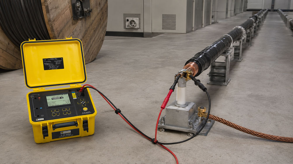
Long electrical cables do not behave like a simple high-resistance load during an insulation test. Electrical capacitance exists between conductors, shield and earth over the entire cable length. The longer the cable, the greater this capacitance generally becomes.
If a DC test voltage of, for example, 500 V, 1,000 V or several kilovolts is applied during insulation testing, this cable capacitance must first be charged. During this charging phase, a sometimes considerable capacitive charging current flows.
The displayed insulation resistance can therefore be significantly lower immediately after the start of the test and then increase continuously.
With long cables, an early reading must therefore not automatically be interpreted as poor insulation resistance. The cable must first be sufficiently charged and the measured value allowed to stabilize.
The end of the test is equally important. A cable charged to several hundred or several thousand volts stores electrical energy and must subsequently be discharged in a controlled manner. The test leads must therefore not be removed immediately after completion of the insulation test.
Suitable test instruments can be found under electrical measuring and test instruments at ICS Schneider.
Table of Contents
- Why does a long cable behave like a capacitor?
- How does cable capacitance increase with length?
- What happens during an insulation test?
- Which current components does the insulation tester measure?
- Understanding capacitive charging current
- Why long cables require more charging time
- Why the charging current of the test instrument matters
- When is the measured value stable?
- Defining a reproducible measurement time
- PI and DAR in time-dependent measurements
- Selecting the correct test voltage
- Preparing a long cable correctly for testing
- Measuring conductor against shield or earth
- How much energy can a cable store?
- Why the cable must be discharged after testing
- Voltage recovery due to dielectric absorption
- Automatic discharge by the test instrument
- Safety measures when testing long cables
- Practical example: 5 km cable at 5 kV
- Typical fault patterns
- Recommended test procedure
- Suitable insulation testers from ICS Schneider
- Conclusion
- FAQ
Why does a long cable behave like a capacitor?
An electrical cable contains conductive components that are separated from one another by insulating materials.
For example:
- conductor to conductor,
- conductor to shield,
- conductor to metallic sheath,
- conductor to earth.
Physically, this arrangement corresponds to a capacitor.
With short cables
the resulting capacitance is often so small that its influence is barely noticeable during a normal insulation test.
With long cables
however, the capacitance adds up over the entire cable length.
A locally small value can therefore result in a total capacitance in the range of:
several hundred nF
or:
several µF
.
For the insulation tester, the cable therefore initially represents a capacitive load that must be charged to the selected test voltage.
How does cable capacitance increase with length?
If the capacitance per unit length of the cable is known, the total capacitance can be estimated.
C = C' · L
where:
C= total capacitance,C'= capacitance per unit length,L= cable length.
Example
A cable has an assumed capacitance per unit length of:
0.20 µF/km
At a cable length of:
5 km
the total capacitance is:
C = 0.20 µF/km · 5 km
therefore:
C = 1.0 µF
However, the actual capacitance strongly depends on:
- cable design,
- conductor arrangement,
- insulation material,
- shielding,
- measurement connection
.
For a specific calculation, the cable manufacturer’s data should therefore be used.
What happens during an insulation test?
An insulation tester applies a defined DC voltage between the selected conductors or between conductor and earth.
The instrument measures the resulting current and calculates the insulation resistance from it.
In simplified form:
R = U / I
where:
R= insulation resistance,U= test voltage,I= measured current.
Immediately after switching on
this current does not consist exclusively of the actual leakage current through the insulation.
Several time-dependent current components overlap.
As a result, a resistance value calculated immediately after the start of the test is often not yet representative of the steady-state insulation condition.
Which current components does the insulation tester measure?
During a DC insulation test, several current components may essentially occur.
Capacitive charging current
It charges the electrical capacitance of the cable.
This component is highest at the beginning and then decreases.
Absorption or polarization current
The molecules of the insulating material align themselves in the applied electric field.
This current usually decreases much more slowly than the purely capacitive charging current.
Leakage current
After sufficient charging and polarization time, the actual current through the insulation and, where applicable, a surface leakage current remain.
This more stable component is particularly relevant for evaluating insulation resistance.
For the measuring instrument, the following therefore applies in simplified form
Itotal = Icharging + Iabsorption + Ileakage
As the test duration increases, the first two components become smaller.
The displayed resistance therefore often initially increases when the insulation is in good condition.
Understanding capacitive charging current
For a capacitance, the following generally applies:
I = C · dU/dt
The greater the cable capacitance, the more current is required to build up the test voltage at a given rate.
The required electrical charge is
Q = C · U
where:
Q= charge,C= capacitance,U= test voltage.
With limited output current from the test instrument
the theoretical charging time can be estimated approximately as:
t ≈ C · U / I
This equation describes only the capacitive charging process.
The actual required measurement time can be considerably longer due to:
- dielectric absorption,
- test-instrument regulation,
- leakage current,
- filtering
.
Why long cables require more charging time
The greater the cable capacitance, the more electrical charge the insulation tester must initially provide.
As a result, the test voltage may rise more slowly to its target value when testing long cables.
During this phase, the following can be observed
- test voltage is still increasing,
- current is initially relatively high,
- displayed insulation resistance increases continuously,
- measured value is not yet stable.
If a value is documented at this stage, a cable that is actually in good condition may incorrectly appear to have poor insulation.
This is particularly critical with
- long power cables,
- shielded cables,
- multi-core cables with high total capacitance,
- long motor cables,
- medium-voltage cables.
Why the charging current of the test instrument matters
Insulation testers differ not only in terms of their maximum test voltage and resistance measurement range.
The available output or charging-current capability can also be decisive for large capacitive test objects.
An instrument with a higher charging current
can generally charge a large cable capacitance to the required test voltage more quickly.
An instrument with a lower charging current
may still be able to measure the same test object, but it will require more time to build up the test voltage.
For large cable systems, the following should therefore be checked:
- maximum test voltage,
- maximum charging current,
- permissible capacitive load,
- automatic discharge,
- residual-voltage indication.
When is the measured value stable?
A measured value is not considered stable merely because the display does not visibly change for a few seconds.
With long cables, it should first be checked whether:
- the required test voltage has actually been reached,
- the charging current has sufficiently decayed,
- the resistance value is only drifting slightly.
Observe the test voltage
Test instruments that display the actual voltage applied to the test object in addition to the insulation resistance are particularly useful.
If, for example, a test voltage of:
1,000 V
is selected but the actual voltage is initially significantly lower, the system may still be in the charging phase.
Do not look only at a single resistance value
The time profile contains important information.
A continuously increasing resistance can represent normal charging and polarization behavior.
Defining a reproducible measurement time
If cables are to be compared regularly with one another or with previous measurements, the reading time should be defined.
For example
Insulation resistance after 60 seconds
instead of simply:
Insulation resistance = 2.4 GΩ
The advantage
Measurements become significantly more reproducible.
At minimum, the following should therefore be documented:
- test voltage,
- test duration,
- measurement connection,
- cable temperature or ambient temperature,
- measured insulation resistance.
For condition comparisons, the time profile of the insulation resistance can also be useful.
PI and DAR in time-dependent measurements
For certain insulation systems, time-dependent parameters such as DAR or PI are used.
DAR
The Dielectric Absorption Ratio compares resistance values at two defined points in time.
PI
The Polarization Index is typically calculated from the ratio of two resistance values measured at different test times.
In simplified form:
PI = R10 min / R1 min
Important
PI and DAR are not universal pass/fail criteria for every cable.
Their significance depends on:
- insulation material,
- cable type,
- temperature,
- application,
- manufacturer or test requirements
.
They should therefore only be used if the test procedure is intended for the specific equipment under test.
Selecting the correct test voltage
The cable length does not determine the required test voltage.
The test voltage depends on:
- rated voltage of the cable or circuit,
- cable design,
- insulation system,
- test objective,
- manufacturer specifications,
- applicable standard or test procedure.
A higher test voltage does not automatically mean a better test.
An unsuitable high DC voltage can subject equipment or connected electronics to impermissible stress.
Before testing, particular attention must be paid to
- electronic assemblies,
- transmitters,
- variable frequency drives,
- power supplies,
- surge-protection components
in accordance with the relevant test and manufacturer requirements, and they may need to be disconnected.
Preparing a long cable correctly for testing
Before starting the insulation test, the cable must be de-energized and disconnected from the normal circuit.
It should also be checked
- whether the cable has actually been isolated,
- whether connected loads have been disconnected,
- whether both cable ends are clearly identified,
- whether no persons are working at the remote cable end,
- whether the selected measurement connection matches the test objective.
Particularly important for long cable runs
The remote end of the cable may be outside the tester’s field of view.
It must therefore be ensured organizationally and technically that no one can access the conductors under test voltage during the test.
Measuring conductor against shield or earth
With shielded power cables, the insulation between conductor and metallic shield or earth is often of interest.
Depending on the test objective, measurements may be carried out, for example, as:
conductor → shield
or, with multi-core cables:
one conductor → remaining connected conductors + shield
Which connection is correct
depends on the cable and the specified test procedure.
The connection configuration must therefore be clearly documented before testing.
Otherwise, measurements from different tests may not be meaningfully comparable even though the same cable is being tested.
How much energy can a cable store?
The energy stored in a charged capacitance is:
E = 1/2 · C · U²
The quadratic dependence on voltage is decisive
If the test voltage is doubled, the stored energy is quadrupled at the same capacitance.
Example with 1 µF
| Test voltage | Stored energy |
|---|---|
| 500 V | 0.125 J |
| 1,000 V | 0.5 J |
| 5,000 V | 12.5 J |
| 10,000 V | 50 J |
This clearly shows why discharging is an essential part of the test procedure, particularly for long cables and high test voltages.
Why the cable must be discharged after testing
After the test voltage is switched off, the cable capacitance initially remains charged.
The voltage must therefore not be assumed to have disappeared simply because the insulation tester has ended the active measurement.
A controlled discharge must take place
Many modern insulation testers perform this function automatically via an internal discharge circuit.
The voltage at the test object then decreases gradually.
During this phase
- leave the test leads connected,
- do not touch the test object,
- observe the residual-voltage indication,
- only continue work after safe discharge has been confirmed.
Removing the test leads before the discharge is complete can result in the cable remaining charged.
Voltage recovery due to dielectric absorption
In addition to the pure cable capacitance, dielectric absorption of the insulating material can also be relevant.
During the test, energy is stored in the insulation system.
After an initial discharge, internal polarization processes may partially equalize again.
This can cause the voltage to rise again
even though the cable was discharged immediately beforehand.
This effect is often referred to as:
dielectric absorption
or:
voltage recovery
.
With large capacitive test objects
a longer discharge time may therefore be required.
For corresponding high-voltage tests, defined grounding of the test object after the measurement may additionally be required.
The exact procedure depends on:
- test voltage,
- cable type,
- stored energy,
- test instrument,
- applicable safety requirements.
Automatic discharge by the test instrument
An automatic discharge function increases safety and simplifies testing of capacitive equipment in particular.
After the test, a suitable instrument should
- switch off the test voltage,
- discharge the test object in a controlled manner,
- display or monitor the remaining voltage,
- warn the operator of hazardous residual voltage.
Important
Automatic discharge does not mean:
release TEST button → immediately remove test leads
.
The discharge time increases with the capacitance of the test object.
With a long cable, it can therefore be noticeably longer than, for example, with a short motor winding or a small electrical device.
Safety measures when testing long cables
An insulation test deliberately generates a high DC voltage.
The test setup must therefore be treated as an active electrical test.
Before the test
- isolate the system or cable,
- secure it against reconnection,
- verify absence of voltage,
- clearly identify the test object,
- secure remote cable ends,
- disconnect unsuitable connected equipment.
During the test
- do not touch test connections,
- use suitable high-voltage test leads,
- secure the test area against accidental access,
- monitor test voltage and measured value.
After the test
- end the test,
- leave the test leads connected,
- wait for automatic or prescribed discharge,
- check residual voltage,
- perform any prescribed additional grounding if required.
Only then should the cable be touched or reconnected.
Practical example: 5 km cable at 5 kV
As an example, a cable has a capacitance of:
0.25 µF/km
and a length of:
5 km
Total capacitance
C = 0.25 µF/km · 5 km
gives:
C = 1.25 µF
Test voltage
For this purely mathematical example, assume a test voltage permitted for the cable concerned of:
5,000 V DC
.
Required charge
Q = C · U
Q = 1.25 µF · 5,000 V
gives:
Q = 6.25 mC
Theoretical charging time at 5 mA
t ≈ Q / I
t ≈ 6.25 mC / 5 mA
ideally gives:
t ≈ 1.25 s
This is only the theoretical capacitive charging time.
The measurement may have to be continued for considerably longer until:
- the test voltage is stable,
- absorption currents have sufficiently decayed,
- the required test time has been reached.
Stored energy
E = 1/2 · C · U²
gives:
E ≈ 15.6 J
This example shows that with long cables, even a comparatively low capacitance can result in a relevant amount of stored energy at high test voltage.
Typical fault patterns
| Observation | Possible cause | Recommended check |
|---|---|---|
| Insulation resistance continuously increases during the test | Cable is still being charged or polarized | Extend test duration and observe actual test voltage |
| Measured value unusually low immediately after start | High capacitive charging current | Do not evaluate immediately; wait for stabilization |
| Test voltage reaches target value only slowly | High cable capacitance | Check capacitance and charging-current capability of the test instrument |
| Measurement fluctuates considerably | Test voltage not yet stable or interference present | Check voltage profile and connections |
| Repeat measurements differ significantly | Different test durations | Define a fixed reading time |
| Measured value initially differs during a repeated test | Cable was not completely discharged beforehand | Extend discharge time |
| Voltage still present at cable after completion of test | High cable capacitance or incomplete discharge | Monitor residual voltage and continue discharging |
| Voltage rises slightly again after initial discharge | Dielectric absorption | Discharge again or for a longer period |
| Insulation value unusually low and constant | Actual leakage current, moisture or damaged insulation | Check measurement connection, cable condition and environment |
| Measurement against shield differs from previous measurement | Different conductor combination used | Compare test configuration |
| Test instrument terminates test due to external voltage | Cable not completely de-energized | Check isolation and verify absence of voltage |
| Test instrument cannot build up high test voltage | Capacitive load too large or insulation resistance too low | Check instrument specifications and test object |
| Electronic assembly damaged after test | Test voltage applied to unsuitable connected equipment | Review test setup and manufacturer requirements |
Recommended test procedure
- Define the test objective: Specify which insulation is to be evaluated.
- Clearly identify the cable: Assign both cable ends correctly.
- Isolate the system: Completely disconnect the cable from the supply.
- Secure against reconnection: Prevent unintended energization.
- Verify absence of voltage: Check before connecting the insulation tester.
- Secure the remote cable end: Prevent access during the test.
- Check connected equipment: Disconnect sensitive electronics if necessary.
- Determine the test procedure: Take cable, system and manufacturer requirements into account.
- Select the test voltage: Use only a voltage permitted for the test object.
- Define the measurement connection: For example, conductor against shield or earth.
- Take cable capacitance into account: Use manufacturer data or existing measurement data.
- Select the test instrument: Consider test voltage, charging current and capacitive load.
- Connect the test leads: Use suitable and specified leads.
- Start the test: Do not touch the hazardous area.
- Observe the actual test voltage: Monitor voltage build-up.
- Wait for the charging phase to finish: Do not evaluate too early.
- Maintain a defined test duration: Create comparable measurement conditions.
- Document the measured value: Record resistance, voltage and time.
- Switch off the test voltage: End the test correctly.
- Leave the test leads connected: Allow automatic discharge.
- Observe residual voltage: Wait until a safe condition is reached.
- If required, perform additional discharge or grounding: Follow test and safety requirements.
- Verify absence of voltage again: Check before further work.
- Only then remove the test leads: Afterwards return the test object to its intended condition.
Suitable insulation testers from ICS Schneider
C.A 6528 – compact insulation tester for cables and electrical installations
The C.A 6528 is suitable for conventional maintenance and testing tasks on electrical installations, motors and cables.
Key functions include:
- test voltages of 250 V, 500 V and 1,000 V,
- insulation measurement up to 11 GΩ,
- manual, locked and timed measurement,
- simultaneous display of insulation value and actual test voltage,
- detection of hazardous external voltage,
- controlled discharge of the test object after measurement.
After completion of the insulation test, the voltage decrease of the discharging test object can be observed on the instrument.
This function is particularly important with long cables because a capacitive test object may require a longer discharge time.
C.A 6524 – insulation testing with PI and DAR
The C.A 6524 is designed for test voltages up to 1,000 V and offers a significantly extended resistance measurement range.
Functions include:
- test voltages from 50 to 1,000 V,
- insulation measurement range up to 200 GΩ,
- manual, locked and timed test mode,
- PI and DAR calculation,
- display of test voltage, test current and timer,
- measurement storage.
The instrument is therefore particularly suitable for testing tasks in which the time-dependent behavior of the insulation or defined measurement times are to be documented.
C.A 6550 – high-performance insulation tester up to 10 kV
For large insulation systems and applications requiring higher test voltages, the C.A 6550 is available.
Key features include:
- adjustable test voltage from 40 V to 10 kV,
- insulation measurement range into the TΩ range,
- maximum charging current of 5 mA,
- capacitance measurement,
- automatic discharge after testing,
- programmable test duration,
- PI, DAR and DD evaluation,
- graphical display of resistance, voltage and current over time.
The available charging current of up to 5 mA is particularly useful for larger capacitive test objects because it allows the required test voltage to be built up more quickly.
C.A 6555 – insulation testing up to 15 kV
The C.A 6555 extends this concept to test voltages up to 15 kV.
It also offers:
- high charging current for capacitive test objects,
- capacitance measurement,
- automatic discharge,
- PI, DAR and DD calculation,
- programmable test sequences,
- extensive measurement storage.
The fact that a test instrument can generate 10 or 15 kV does not mean that this voltage may be used on every cable. The permissible test voltage must always be defined for the specific test object.
Further instruments can be found under electrical measuring and test instruments at ICS Schneider.
Conclusion
When insulation-testing long cables, the electrical capacitance of the cable must always be considered in addition to the actual insulation resistance.
The longer the cable, the greater its capacitance can become
This increases the electrical charge that the insulation tester must initially provide.
A low initial value does not automatically mean poor insulation
During the charging and polarization phase, the total current is increased. The resulting calculated insulation resistance can therefore initially appear significantly lower.
The test voltage must be fully established
Only when the test voltage is stable and after a defined measurement time can results be meaningfully evaluated and compared.
The charging current of the test instrument can be decisive
Large capacitive test objects can be brought to the required test voltage more quickly with a suitably powerful test instrument.
The test voltage does not depend on cable length
It must be selected according to cable type, rated voltage, manufacturer specifications and the applicable test procedure.
Energy remains stored after the test
A long cable can behave like a charged capacitor.
Automatic discharge must be allowed to complete
The test leads must not be removed until the test object has been safely discharged.
Voltage can recover even after an initial discharge
Dielectric absorption can cause voltage to build up again, particularly in large insulation systems.
For practical applications
Clearly isolate and secure the cable → define the test object and measurement connection → determine the permissible test voltage → take cable capacitance into account → select a suitable insulation tester → start the test → wait until the full test voltage is established → perform the measurement for a defined period → document the measured value → switch off the test voltage → leave the test leads connected → wait for automatic or prescribed discharge → check residual voltage → only then remove the test setup.
FAQ: Insulation Testing of Long Cables
Why does insulation testing take longer with a long cable?
Because the cable has electrical capacitance that must first be charged to the selected test voltage.
Why does a cable have capacitance?
Conductors, shield and earth form conductive surfaces that are insulated from one another and therefore behave similarly to a capacitor.
Does capacitance increase with cable length?
Yes. With the same cable design, the total capacitance increases approximately in proportion to length.
How is the total capacitance calculated?
If the capacitance per unit length is known, approximately C = C’ × L applies.
Why is the insulation resistance often lower at the beginning?
At the beginning, a capacitive charging current and an absorption or polarization current flow in addition to the actual leakage current.
Why does the insulation resistance increase during the test?
The transient current components decrease as charging and polarization time increase. This reduces the total current and increases the calculated resistance.
When may I read the insulation resistance?
After the required test voltage has been reached and at the specified or defined test time.
Should the measurement duration be documented?
Yes. Particularly for repeat measurements, a defined test duration is important so that results remain comparable.
Why is the charging current of the insulation tester important?
A higher available charging current can charge large cable capacitances to the required test voltage more quickly.
How can the theoretical charging time be estimated?
With approximately constant charging current, t ≈ C × U / I can be used. However, the actual measurement time can be considerably longer due to absorption processes.
What does Q = C × U mean?
The equation describes the electrical charge stored by a capacitance at a given voltage.
How is the stored energy calculated?
With E = ½ × C × U².
Why is the test voltage so critical in the energy formula?
Because energy increases with the square of the voltage. Doubling the voltage quadruples the stored energy.
Is a long cable immediately de-energized after switching off the test voltage?
No. The cable capacitance may remain charged and must be discharged in a controlled manner.
May I remove the test leads immediately after testing?
No. During automatic discharge, the test leads should remain connected until the test instrument indicates a safe condition.
What is an automatic discharge function?
After completion of the measurement, the test instrument connects the capacitive test object to an internal discharge circuit and thereby reduces the residual voltage in a controlled manner.
Why can discharging a long cable take longer?
Because increasing capacitance means that more electrical charge and potentially more energy are stored.
Can voltage reappear after discharge?
Yes. Due to dielectric absorption, voltage can build up again after an initial discharge in certain insulation systems.
What is dielectric absorption?
During the test, polarization processes build up in the insulating material and only decay gradually after the test voltage is switched off.
What is DAR?
DAR is a time-dependent ratio of insulation resistance values measured at two defined times.
What is PI?
The Polarization Index is a ratio of time-dependent insulation resistance values, often the resistance after 10 minutes divided by the resistance after 1 minute.
Is a high PI automatically good for every cable?
No. Its significance depends on insulation material, cable design and the specified test procedure.
Which test voltage should be used for a cable?
The test voltage depends on cable type, rated voltage, manufacturer specifications and the applicable test or safety procedure.
Should I simply use a higher test voltage for a long cable?
No. Cable length is not a criterion for increasing the test voltage.
Why may electronic devices need to be disconnected?
An insulation-test voltage may exceed the permissible input voltage of connected electronics and damage them.
How is a shielded cable tested?
Depending on the test objective, for example between one conductor and shield or earth. The exact connection configuration must correspond to the prescribed test procedure.
Why must the remote cable end also be secured?
Because the test voltage is present along the entire cable and, with long cables, the opposite end is often outside the tester’s field of view.
Can an insulation tester detect that external voltage is still present?
Suitable instruments have voltage monitoring and prevent or warn against insulation testing on an energized test object.
Which instrument is suitable for conventional cable testing up to 1,000 V test voltage?
The C.A 6528 is designed for insulation tests at 250 V, 500 V and 1,000 V and provides controlled discharge after the measurement.
Which instrument provides PI and DAR evaluation up to 1,000 V?
The C.A 6524 offers test voltages from 50 to 1,000 V as well as PI and DAR functions.
Which instrument is suitable for large capacitive test objects and higher test voltages?
The C.A 6550 provides test voltages up to 10 kV and a maximum charging current of 5 mA.
Which version is available for test voltages up to 15 kV?
The C.A 6555 extends the test-voltage range up to 15 kV. These high voltages may only be used if they are specified for the particular test object.
Where can I find further insulation testers?
Further solutions can be found under electrical measuring and test instruments at ICS Schneider.