


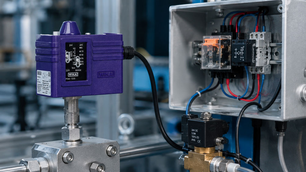
A pressure switch is intended to switch a solenoid valve, contactor or relay when the set pressure is reached. The nameplate may state, for example, “10 A at 230 V AC”, while the connected coil requires only 0.6 A. Nevertheless, the contacts may burn out after a short time or weld together when switching on. This apparent contradiction arises because the rated current alone does not describe the actual electrical load on the switching contact.
Coils, solenoid valves, contactors and motors are inductive loads. When switched off, they release the energy stored in their magnetic field as a voltage spike. An arc can form between the opening contacts, removing material, altering the contact surface and significantly reducing service life. Suitable arc suppression or an interposing relay can control this load – provided the protective circuit, switching voltage and required release time are considered together.
Why the Printed Rated Current Is Not Enough
The specified maximum voltage and maximum current always apply under defined test conditions. They do not automatically mean that every type of load may be switched at this current. With a resistive heater, current and voltage are largely in phase. A coil, however, generates dynamic loads during switching on and off that place greater stress on the contact.
At least the following information is required for correct selection:
- switching voltage and current type, AC or DC,
- continuous current and inrush current of the load,
- type of load and, where applicable, utilization category,
- switching frequency and expected number of switching cycles,
- normally open, normally closed or changeover function,
- ambient temperature, vibration and atmosphere,
- permissible coil release time,
- protective circuitry already integrated into the load.
The electrical service life is not a fixed property of the pressure switch. It depends heavily on the actual load and switching process. For this reason, Omron also recommends in its safety precautions for relay contacts that inductive loads be tested under actual operating conditions and that the specified contact ratings are not exceeded.
What Happens When a Coil Is Switched Off
An energized coil stores energy in its magnetic field. In simplified form:
E = ½ × L × I2
Here, L represents the inductance and I the coil current. When the pressure switch opens the circuit, the inductance attempts to maintain the current flow. Because the current decreases very quickly, a high counter-voltage can be generated. This voltage can ionize the air gap between the contacts as they open – creating an electrical arc.
The arc prolongs the current flow, heats the contact surfaces and transfers material from one contact to the other. Possible consequences include:
- contact erosion and increasing contact resistance,
- contact welding and failure to switch off,
- interference pulses in adjacent signal and control lines,
- unstable switching or sporadic system faults,
- significantly reduced electrical service life.
The protective circuit provides a defined path for dissipating the stored energy and limits the voltage across the contact. However, it only provides reliable protection if it is matched to the current type, coil and switching function.
Distinguishing Between Resistive, Inductive and Capacitive Loads
| Load type | Typical examples | Main contact load |
|---|---|---|
| Resistive | Heating resistor, purely resistive load | Current during steady-state operation; comparatively favorable switching behavior |
| Inductive | Relay, contactor and solenoid valve coils, motors | Switch-off overvoltage, arcing and, in some cases, high inrush current |
| Capacitive | Power supply input, capacitor, LED driver | Very high short-duration inrush current and possible contact welding |
| Incandescent lamp | Signal lamp with filament | High inrush current caused by the cold filament |
Even if two loads draw the same current during normal operation, they can place completely different stresses on the contact. For motors and larger contactors, simply classifying the device as a “coil” is often insufficient. Inrush current, power factor, utilization category and manufacturer approval must also be checked separately.
Why DC Is More Difficult to Switch Than AC
With alternating current, the current naturally passes through zero during every cycle. This helps extinguish an electrical arc. With direct current, there is no natural zero crossing. The arc can therefore persist for longer, particularly at higher voltages and with inductive loads.
An AC contact rating must therefore not be transferred directly to a DC application. Even if the numerical values for voltage and current appear lower, the permissible DC switching capacity may be considerably lower. Only the DC contact rating specified for the particular pressure switch, or written manufacturer approval, is decisive.
Polarity can also be relevant for certain DC contacts. Contacts must not be connected in series or parallel in order to increase the permissible voltage or current unless the manufacturer explicitly approves such a configuration. With contacts connected in parallel, exactly simultaneous current sharing cannot be guaranteed.
How to Read Contact Ratings Correctly in the Data Sheet
A good data sheet distinguishes between different current types and load categories. For the WIKA PSM-520 available from the ICS shop, for example, the electrical rating specified by the manufacturer is up to 10 A at 230 V AC for a resistive AC-1 load, while 6 A at 230 V AC is specified for an inductive AC-15 load. The lower value is the decisive one for the inductive application – not the more prominent maximum rating.
In addition to switching capacity, the following data must also be checked:
- maximum voltage and maximum current must not be exceeded individually,
- the specified electrical service life applies only to the corresponding test load,
- the thermal continuous current is not automatically the permissible switching capacity,
- a minimum contact load may be relevant for reliable switching of small signals,
- degree of protection, terminal assignment and permissible conductor cross-section must suit the installation.
If no suitable rating is specified for the actual load, an interposing relay or contactor with clearly suitable contacts is usually the more robust solution.
Protecting DC Coils with a Flyback Diode
For a DC coil, a flyback diode connected in antiparallel with the coil is a simple and effective protective measure. When the coil is energized, the diode remains reverse-biased. When the contact opens, the diode carries the coil current and allows the stored energy to decay within the coil circuit. This greatly limits the switch-off voltage.
Four points are particularly important:
- The polarity of the diode must match the supply voltage.
- Reverse voltage, forward current and energy rating must be adequately dimensioned.
- The diode should be connected as close as possible to the coil.
- If the supply polarity is reversed, a simple flyback diode can cause a short circuit; fuse protection and the connection concept must therefore be designed accordingly.
For DC loads, Omron considers the diode a particularly effective contact protection measure. At the same time, it increases the release time of relays and solenoid valves because the current decays slowly. This effect must be taken into account for safety-related or time-critical functions.
When a Valve or Relay Must Release Quickly
A simple flyback diode limits the voltage very effectively, but it also results in the slowest decay of the magnetic energy. If a solenoid valve must close quickly or a contactor must release rapidly, a combination of diode and Zener diode or a suitable TVS solution may be appropriate. The higher permitted clamping voltage allows the magnetic field to collapse more quickly.
However, the protective voltage must not exceed the contact rating or the insulation limits of the coil, wiring or connected electronics. Faster release is achieved at the cost of a higher voltage spike. The design must therefore be based on the coil data and the approvals of the manufacturers involved. For safety functions, it must also be checked whether the modified release time affects the required response time.
Selecting RC Networks and Varistors for AC Loads
A simple diode is not suitable for alternating voltage. For AC coils, RC networks or varistors are commonly used:
- RC network: A capacitor and resistor limit the rate of voltage rise and suppress the arc. The values must be matched to the coil and switching voltage.
- Varistor: Becomes conductive above its response voltage and limits voltage spikes. Its voltage rating, pulse energy and ageing characteristics must be taken into account.
- Preassembled suppression module: Provides a defined and touch-safe solution for a specific coil voltage and is often the simplest option.
Depending on the circuit, an RC network can allow a small current to flow through the load even when the contact is open. This can prevent sensitive relays, small contactors or electronic inputs from fully releasing. In addition, the capacitor may cause a brief charging current when the contact closes again. In its guidance on contact protection circuits, Omron explicitly recommends checking the effect and modified release time in the actual application.
For mains voltage applications, the capacitor, resistor, insulation distances and enclosure must be approved for the application. An arbitrary capacitor from an electronics assortment is not a suitable substitute for a specified suppression module.
Positioning Protective Circuits Correctly
Protection is most effective when the conductor loop between the coil and protective component is kept short. A flyback diode, varistor or RC module should therefore be installed as close as possible to the inductive load. This also reduces radiated interference affecting adjacent control lines.
Depending on the circuit, an RC network may be connected either in parallel with the load or in parallel with the contact. The two arrangements have different effects on leakage current, EMC and switch-on loading. The position should therefore not be chosen out of habit, but according to the circuit diagram and manufacturer recommendation.
The protective circuit for the coil does not replace protection of the load circuit. Conductor protection, short-circuit protection, safe isolation, overvoltage protection and grounding must be designed separately. Work on electrical installations must only be carried out by qualified personnel with the system de-energized and secured against being switched on again.
When an Interposing Relay Is Recommended
An interposing relay reduces the load on the pressure switch: its contact only switches the relatively small coil current of the interposing relay. The actual load is switched via relay or contactor contacts designed for the purpose. This is particularly useful for:
- high load or inrush currents,
- applications where there is no clear approval for the specific load,
- frequent switching cycles,
- multiple circuits that need to be switched,
- applications requiring galvanic isolation,
- providing an easily replaceable wear component in the control cabinet.
The interposing relay does not eliminate the inductive load completely, because its own coil is itself an inductive load. It therefore also requires suitable protective circuitry. However, the pressure switch contact now only switches a small and precisely known coil current. On the load side, relay contacts are selected whose AC/DC switching capacity, utilization category and service life are suitable for the actual load.
For very frequent switching, a solid-state relay may be an alternative. Leakage current, voltage drop, power dissipation, short-circuit behavior and safe shutdown must then be checked. A semiconductor output is not automatically suitable for every DC or AC load.
Normally Open, Normally Closed and Fail-Safe Logic
A changeover contact usually provides COM, NO and NC terminals. Which contact should be used depends not only on whether the load is intended to switch on at high or low pressure. The behavior in the event of a cable break, power failure or disconnected plug is also important.
For alarm and shutdown functions, an energized-to-run principle is often used: the interposing relay is energized during normal operation and releases in the event of a limit condition, cable break or power failure. This allows certain faults to be detected. Whether this logic is actually fail-safe must, however, be determined from the risk assessment and the complete safety circuit. Using the normally closed contact does not automatically turn a standard pressure switch into a safety function.
Switching Frequency, Hysteresis and Pressure Pulsation
Even a correctly dimensioned contact protection circuit can wear prematurely if the pressure switch chatters around the switching point. Pressure pulsations, insufficient hysteresis, an unfavorable installation point or a rapidly cycling pump can generate a very high number of switching cycles within a short period of time.
Depending on the application, possible remedies include:
- suitable switching differential or hysteresis,
- a pressure measurement point with stabilized flow conditions,
- a restrictor or pulsation damper, provided this is permissible for the process,
- a time delay in the control system,
- an electronic pressure switch with adjustable hysteresis and delay.
A time delay must not be added to a protective function without careful consideration. Required response time, permissible maximum pressure and fault conditions must still be taken into account.
Practical Example: Safely Controlling a 24 V Solenoid Valve
A mechanical pressure switch is intended to control a 24 V DC solenoid valve at 6 bar. The valve coil draws 0.7 A during operation. The DC contact data of the pressure switch do not provide clear approval for this inductive load. In addition, the valve must close within a defined time when the pressure drops.
- Do not switch the load directly: The pressure switch controls the low-current 24 V DC coil of an interposing relay.
- Protect the relay coil: The coil is fitted with a suppression module suitable for the relay. Its influence on the release time is checked.
- Switch the valve using a suitable contact: The relay contact is selected according to its DC switching capacity for a solenoid valve coil, not merely according to its thermal continuous-current rating.
- Protect the valve coil: Because rapid closing is required, the suppression circuit approved by the valve manufacturer is used. A simple diode is not installed without checking its effect first.
- Protect and test the circuit: The load and control circuits are protected with suitable fuses. Switching behavior, release time, temperature rise and repeated switching are then tested under actual pressure conditions.
The interposing relay reduces the electrical load on the pressure switch contact, which is generally more difficult to replace. At the same time, the load side can be clearly dimensioned and remains easier to maintain.
Planning and Commissioning Checklist
- Determine the load type, supply voltage and actual current consumption, including inrush current.
- Check the AC/DC contact ratings and suitable utilization category of the pressure switch.
- Define the required switching function, hysteresis and maximum switching frequency.
- Select direct switching or an interposing relay based on the application.
- Select the protective circuit according to the type of current, coil data and permissible release time.
- Install the protective component close to the coil and route the wiring in an EMC-compatible manner.
- Dimension conductor and short-circuit protection as well as safe electrical isolation.
- Clearly document the COM, NO and NC assignments in the circuit diagram.
- Check operation at the minimum and maximum supply voltage.
- Verify switching time, contact condition and temperature under the actual load.
Common Mistakes
- Using the resistive rated current: The inductive load is only approved for a lower current.
- Using an AC rating for DC: The absence of a natural current zero crossing is ignored.
- Incorrectly polarized flyback diode: A short circuit occurs when the supply is switched on.
- Using a diode without checking the release time: The solenoid valve or contactor releases too slowly.
- Arbitrarily dimensioning an RC network: Leakage current, switch-on pulses or insufficient suppression cause additional problems.
- Installing the suppressor too far away: The long conductor loop continues to radiate interference.
- Using an interposing relay without coil protection: The pressure switch is once again switching an unprotected inductive load.
- Connecting contacts in parallel: Non-simultaneous switching results in uneven current sharing.
- Ignoring pressure-induced contact chatter: A high switching frequency shortens service life even with a small load.
- Testing only without a load: The actual switch-off behavior of the load remains unknown.
Suitable Pressure Switches
For conventional pump, compressor and monitoring applications, the WIKA PSM-520 is a suitable mechanical solution. The switching point can be adjusted on site. Particularly relevant to this subject is the separate specification of the contact ratings: up to 10 A at 230 V AC for resistive loads and 6 A at 230 V AC for inductive AC-15 loads. This model is therefore also the first choice for the accompanying article image.
For harsh process environments and applications with special enclosure or approval requirements, the WIKA PXA available in the shop, with flameproof enclosure, may be suitable. The contact version, electrical switching capacity and explosion protection must be selected to suit the specific application.
If the pressure value is primarily intended to be transmitted to a PLC and the load is switched via the control system, an electronic pressure switch such as the WIKA PSD-4 may be more suitable. However, its switching output may likewise only be loaded within the specified output ratings; a transistor output does not replace a correctly dimensioned relay for larger coils.
An overview of the available mechanical and electronic versions can be found in the Pressure Switches / Differential Pressure Switches category.
Conclusion
When switching a coil, the operating current alone does not determine whether a pressure switch is suitable. Current type, load category, switch-on behavior, switch-off overvoltage, switching frequency and required release time must all be evaluated together. A high resistive contact rating does not constitute general approval for solenoid valves, contactors or motors.
For DC coils, a flyback diode is usually the most effective simple method of contact protection, although it can delay release. RC networks or varistors are typically used for AC coils. An interposing relay reduces the load on the pressure switch and makes the load side easier to dimension and replace. The decisive factor remains testing the complete circuit under actual operating conditions.
FAQ: Pressure Switches with Inductive Loads
Can a pressure switch with a 10 A contact directly switch a 2 A solenoid valve?
Not automatically. The 10 A rating may apply to a resistive AC load. For the solenoid valve, the current type, inductive contact rating, inrush current and protective circuitry must be checked.
Where is the flyback diode connected?
It is connected in antiparallel and as close as possible to the DC coil. During normal operation, it must remain reverse-biased. Its polarity and electrical ratings must suit the supply and the coil.
Why does a solenoid valve release more slowly when a flyback diode is used?
After switching off, the diode allows the coil current to continue flowing in a closed circuit. The magnetic field therefore decays slowly and with only a low overvoltage.
Can a flyback diode also be used with a 230 V AC coil?
No. For alternating voltage, RC networks, varistors or suitable AC suppression modules are used depending on the load and manufacturer approval.
Is an RC network better connected in parallel with the contact or with the coil?
This depends on the voltage, load, required EMC performance and permissible leakage current. Both arrangements have different side effects. The selection should be based on the manufacturer recommendation and testing in the actual circuit.
Does an interposing relay completely protect the pressure switch?
It significantly reduces the load on the pressure switch, but the relay coil itself is also inductive and may require protective circuitry. In addition, the relay contacts must be suitable for the actual load.
Why is a contact more likely to weld when switching on?
A high inrush current may be the cause, for example with motors, contactors, lamps or capacitive inputs. The current can briefly be considerably higher than the steady-state operating value.
How can contact chatter at the pressure switch be prevented?
By using suitable hysteresis, a pressure measurement point with stabilized conditions, pulsation damping where appropriate, and a permissible time delay. The selected measure must remain compatible with the required response time.