


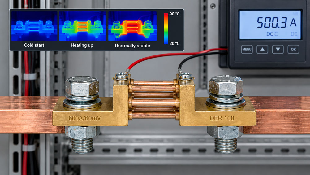
A DC circuit is monitored using a measuring shunt. Immediately after switch-on, the measuring instrument indicates, for example, 500 A. After several minutes of continuous operation, the indication rises to 503 A despite the load apparently remaining unchanged. Cables, power supply and load are operating stably. What could be causing the change?
One possible cause is self-heating of the shunt. Although a measuring shunt has a very low resistance, the full load current flows through it. This produces power dissipation. As the temperature rises, the electrical resistance of the shunt material can also change slightly.
Since the measuring instrument determines the current from the voltage drop across the shunt, a temperature-dependent resistance directly changes the current indication. In addition, installation location, air circulation, adjacent busbars and control-cabinet temperature influence the thermal equilibrium.
For precise shunt current measurement, it is therefore not sufficient to consider only rated current and rated voltage drop. Power dissipation, temperature coefficient, installation conditions and thermal stabilization are also part of the measuring chain.
How does current measurement with a shunt work?
A measuring shunt is a very low-resistance precision resistor installed in series with the current circuit to be measured.
The load current produces a small voltage drop across the resistor.
According to Ohm’s law:
U = I × R
The current can therefore be determined from:
I = U / R
A shunt rated:
500 A / 60 mV
has a calculated resistance of:
R = 0.060 V / 500 A = 0.00012 Ω
or:
120 µΩ
At 500 A, a voltage drop of 60 mV is generated across this resistance. The connected measuring instrument can, for example, scale this signal to an indication of 0…500 A.
This current measurement assumes that the actual resistance of the shunt is sufficiently stable and known.
Why does a low-resistance shunt heat up at all?
Even a very small resistance converts electrical power into heat.
The power dissipation is:
P = I² × R
For the example shunt with:
R = 120 µΩ
and:
I = 500 A
the result is:
P = 500² × 0.00012 Ω = 30 W
This 30 W of power must be continuously dissipated to the environment or conducted away through the connections and busbars.
A shunt can therefore become significantly warmer than its surroundings during continuous operation despite its very low resistance.
What does the temperature coefficient of resistance mean?
The electrical resistance of a real material depends on temperature.
The temperature coefficient – often referred to as TCR, or temperature coefficient of resistance – describes in simplified form how strongly the resistance changes with temperature.
Over a small temperature range, this can be approximated by:
R(T) ≈ R₀ × [1 + α × (T - T₀)]
Where:
R(T)= resistance at the current temperature,R₀= resistance at the reference temperature,α= temperature coefficient,T - T₀= temperature change.
Precision shunts use materials or designs intended to keep this temperature influence as small as possible.
However, small does not automatically mean zero.
For an actual calculation, the specified temperature coefficient of the specific shunt must therefore be used.
How does a change in resistance become a current measurement error?
A typical indicator is scaled to the nominal value of the shunt.
For example:
60 mV = 500 A
This relationship is based on the intended resistance value.
If the actual resistance increases due to temperature, the same real current produces a slightly larger voltage drop.
The measuring instrument interprets this larger voltage drop as a higher current.
For example, assume:
R cold = 120.00 µΩ
and after heating:
R warm = 120.24 µΩ
This corresponds to a resistance change of:
+0.2 %
With the real current unchanged, the voltage drop also increases by approximately 0.2 %.
A measuring system without corresponding compensation would therefore also indicate approximately 0.2 % too high.
The numerical values are intended only to illustrate the principle. For a specific shunt, the specified temperature data of that shunt are decisive.
Why is operation at rated current thermally demanding?
Power dissipation increases with the square of the current.
If a shunt is operated at its rated current, the maximum continuous power dissipation intended for this operating condition is generated.
The design must be capable of dissipating this heat to the environment or through the electrical connections.
At a minimum, the following should therefore be considered when selecting a shunt:
- continuous current,
- maximum operating current,
- duty cycle,
- ambient temperature,
- mounting conditions,
- permissible overload.
A shunt with a sufficiently high rated current must therefore be designed not only electrically, but also thermally.
How much does heating decrease at partial load?
Because power dissipation is proportional to the square of the current, it decreases disproportionately when the current is reduced.
If the same 500 A shunt is operated at only:
250 A
the power dissipation is:
P = 250² × 0.00012 Ω = 7.5 W
The current has been halved, but the power dissipation is only one quarter of the original value.
| Current | Relative current | Relative power dissipation |
|---|---|---|
| 500 A | 100 % | 100 % |
| 400 A | 80 % | 64 % |
| 250 A | 50 % | 25 % |
| 100 A | 20 % | 4 % |
This is why a shunt can behave thermally very differently at 20 % of rated current than during continuous operation close to rated current.
Why does a shunt require thermal stabilization time?
After switch-on, the temperature of the shunt does not immediately jump to its final value.
First, power dissipation is generated in the resistance element. Then the following components heat up:
- the resistance element,
- connection blocks,
- busbars,
- bolted connections and
- the air immediately surrounding the shunt.
At the same time, heat is released to the environment.
After a certain period, a thermal equilibrium is established:
generated heat ≈ dissipated heat
Only then does the shunt temperature remain largely constant under unchanged operating conditions.
For high-accuracy measurements, it may therefore be appropriate to consider a measured value as the reference or steady-state value only after sufficient thermal stabilization.
What role does cooling play?
The operating temperature of a shunt depends on how effectively the dissipated heat can be removed.
Possible heat-transfer paths include:
- heat conduction through the connection bolts,
- heat conduction into cable lugs or busbars,
- natural convection to the surrounding air,
- forced-air cooling,
- thermal radiation.
A freely mounted shunt in a well-ventilated control cabinet can therefore reach a different equilibrium temperature from the same component inside a small, enclosed housing.
Neighbouring heat sources also influence the situation.
Good cooling does not directly improve the electrical accuracy class of the shunt, but it can reduce the temperature rise and therefore reduce temperature-dependent resistance changes.
Why does the installation position influence the measurement result?
With natural convection, heated air rises.
The physical arrangement therefore affects:
- how effectively air can flow past the shunt,
- whether warm air accumulates,
- whether several shunts heat one another,
- whether heat sources are positioned directly below the shunt.
Manufacturer specifications concerning installation position and minimum clearances should therefore be observed.
In particular, several high-current shunts should not be mounted close together without considering the thermal conditions.
What role do busbars and connection cables play?
The high-current connections are both electrical and thermal interfaces.
Massive copper busbars can conduct heat away from the shunt.
At the same time, bolted connections and cable lugs have their own contact resistances.
A poor high-current connection can therefore:
- generate additional power dissipation,
- cause local heating,
- thermally influence the shunt,
- cause voltage drops outside the actual measuring resistor.
For thermal diagnostics, the resistance element itself should therefore not be considered in isolation.
Hot connection bolts can indicate a contact problem even if the shunt itself is correctly dimensioned.
Why must sense leads be connected separately?
The voltage drop across a shunt is typically only a few tens or hundreds of millivolts.
The measuring leads should therefore be connected directly to the designated sense terminals.
The high-current connection and the voltage sensing point serve different purposes:
- High-current connection: carries the load current,
- Sense connection: measures only the defined voltage drop across the shunt.
If the measurement voltage is instead taken, for example, from the cable lugs or from a point further away on the busbar, additional contact and conductor resistances can become part of the measurement signal.
These resistances can also heat up and introduce additional temperature-dependent errors.
The separate voltage measurement therefore corresponds to the principle of a four-wire or Kelvin measurement.
What happens at high control-cabinet temperatures?
A shunt does not heat up from a fixed room temperature, but from its actual ambient temperature.
If the air temperature inside the control cabinet is already significantly above normal room temperature, the shunt begins operation from a higher temperature level.
Additional heat sources can include:
- power supplies,
- frequency converters,
- contactors,
- power semiconductors,
- other high-current busbars.
The nominal room temperature of the building should therefore not be used as the only basis for design.
The relevant value is the actual ambient temperature at the installation point under maximum system load.
What is the effect of short-term overcurrents?
A short-term overcurrent can produce a significantly higher instantaneous power dissipation.
If the current briefly doubles, for example, the calculated power dissipation increases to four times its previous value.
Because of the thermal mass, the temperature does not immediately increase proportionally during a very short pulse.
However, if such load peaks occur frequently, the average temperature can increase significantly.
The following must therefore be considered when selecting a shunt:
- peak current,
- pulse duration,
- repetition rate,
- permissible short-term overload.
A selection based only on the normal continuous current may be insufficient in applications with strong charging, starting or discharging currents.
Practical example: 500 A shunt heats up during continuous operation
A shunt rated:
500 A / 60 mV
is used for current measurement in a DC test bench.
The actual load current is confirmed by an independent reference to be approximately:
400 A
.
Immediately after switch-on, the shunt indication agrees very well with the reference.
After 20 minutes, however, the shunt measuring system indicates a slightly higher value.
Investigation shows that:
- the load current is stable,
- the sense leads are connected correctly,
- the shunt becomes noticeably warmer,
- the indication stabilizes in parallel with the shunt temperature.
The effect is also reproducible: after the shunt has completely cooled down, the same behaviour starts again after the next switch-on.
The diagnosis therefore points to a thermal influence rather than random electrical interference.
It is then checked whether the observed deviation lies within the permissible specification for the actual shunt and measuring system.
This example shows that a reproducible change during the warm-up phase can be normal thermal behaviour of the measuring chain – the decisive factor is whether it remains within the specified limits.
Systematically diagnosing temperature-related measurement deviation
- Check the actual load current using a suitable reference.
- Check the rated current and rated voltage drop of the shunt.
- Calculate the power dissipation at the current operating current.
- Record the shunt temperature or temperature profile.
- Document the measured value during the warm-up phase.
- Check whether the measured value and temperature drift in correlation with one another.
- Check the sense connections.
- Check the high-current connections for heating.
- Check air circulation and installation position.
- Take neighbouring heat sources into account.
- Refer to the temperature coefficient or manufacturer data.
- Repeat the measurement after the shunt has completely cooled down.
Systematic design and testing
- Determine the normal continuous current.
- Determine the maximum continuous current.
- Identify short-term current peaks.
- Select the appropriate shunt rated current.
- Select the rated voltage drop to match the measuring instrument.
- Calculate shunt resistance and power dissipation.
- Check the thermal installation conditions.
- Observe the manufacturer’s specifications for clearance and installation position.
- Dimension the high-current connections adequately.
- Connect the sense leads separately to the measurement terminals.
- Operate the measuring system under typical continuous load.
- Observe the temperature and measured-value trends.
- Document the measured value after thermal stabilization.
- Check behaviour at the maximum intended continuous current.
Common mistakes
- Considering only the rated current: Power dissipation and thermal installation conditions are then not evaluated.
- Ignoring the temperature coefficient: A change in resistance directly changes the mV/A relationship.
- Measuring immediately after switch-on: The shunt may not yet have reached its thermally stable operating condition.
- Equating display resolution with overall accuracy: Temperature drift of the shunt is unaffected by display resolution.
- Connecting sense leads to the high-current cable lugs: Additional contact voltage drops can become part of the measurement signal.
- Ignoring a poor high-current connection: Local heating at the connection can additionally influence the shunt thermally.
- Mounting shunts too close together: Mutual heating can increase operating temperature.
- Equating control-cabinet temperature with room temperature: The actual environment around the shunt can be significantly warmer.
- Changing active cooling afterwards: A different airflow can also change the thermal measuring condition.
- Considering only continuous current: Repeated current peaks can increase the average thermal load.
- Interpreting temperature drift as a defect: It should first be checked whether the effect is reproducible and within specification.
DER 060 / 100 / 150 as measuring shunts for high DC currents
ICS Schneider offers the DER 060, DER 100 and DER 150 series of shunt resistors for indirect measurement of high DC currents.
The shunts generate an mV voltage drop proportional to the load current, which can be evaluated by a connected measuring instrument.
The DER 100, for example, is available for primary currents of:
1 ... 6000 A
.
The available rated voltage drops are:
60 mV,100 mVor150 mV
.
The product description specifies accuracy class 0.5.
For a specific thermal design, the technical data of the selected shunt version, the operating current and the actual installation conditions must also be taken into account.
Especially at high continuous currents, selection should not be based solely on the maximum measurable current. Power dissipation, temperature rise, connection cross-sections and cooling are part of the overall design.
Suitable products can be found under DER 100 shunt resistor and under shunt resistors at ICS Schneider.
Conclusion
A measuring shunt is not a thermally neutral component. Although its resistance is very low, the full load current generates power dissipation that heats the shunt.
Because power dissipation increases with the square of the current, the thermal situation becomes particularly relevant during continuous operation close to the rated current.
As the temperature rises, the resistance of the shunt can change slightly. Since the current indication is based on the relationship between current and the mV voltage drop, this resistance change directly becomes a measurement error.
How warm the shunt actually becomes depends not only on its electrical load. Connection cross-sections, busbars, installation position, air circulation, control-cabinet temperature and neighbouring heat sources influence the thermal equilibrium.
For high-accuracy or reproducible measurements, it should therefore also be considered whether the measurement is taken immediately after switch-on or only after thermal stabilization.
For reliable shunt current measurement, the following therefore applies: select rated current and voltage drop appropriately, calculate power dissipation, consider thermal installation conditions, connect the sense leads correctly and, for demanding applications, evaluate the measured value only after a defined or stable thermal condition has been reached.
FAQ: Heating and temperature errors in current shunts
Why does a shunt become warm?
The full load current flows through the low-resistance element. According to P = I² × R, electrical power is therefore dissipated and converted into heat.
Can a shunt become hot despite its very low resistance?
Yes. At several hundred or several thousand amperes, even a resistance in the micro-ohm or milliohm range can generate considerable power dissipation.
Does temperature influence the current measurement?
Yes. If the resistance of the shunt changes with temperature, the voltage drop at the same real current also changes, and therefore so does the current indication calculated by the measuring instrument.
What does temperature coefficient mean for a shunt?
The temperature coefficient describes how strongly the electrical resistance changes with temperature. For accurate calculations, the value specified for the particular shunt version must be used.
Why is the error larger at high current?
Power dissipation increases with the square of the current. As a result, self-heating increases much more strongly at high load.
How much power dissipation does a 500 A / 60 mV shunt generate?
At rated current, the electrical power dissipation is P = U × I = 0.060 V × 500 A = 30 W.
Does a shunt need to warm up before an accurate measurement?
For applications with high accuracy requirements, it may be appropriate to wait until the thermally stable condition has been reached. Manufacturer data and the requirements of the particular application are decisive.
Does a fan improve measurement accuracy?
A fan does not change the fundamental accuracy class of the shunt. However, it can reduce the operating temperature and therefore reduce temperature-dependent resistance changes. The permissible installation conditions must still be observed.
Why are separate sense connections important?
They measure the voltage drop directly across the defined shunt resistance. This largely separates additional voltage drops at high-current connections and conductors from the actual measurement.
Can a loose cable lug influence the measured value?
Yes. Increased contact resistance can generate additional heat. If the measurement voltage is also taken at an unfavourable point, the additional voltage drop can directly affect the measured value.
Why should the control-cabinet temperature be considered?
It determines the starting or ambient temperature of the shunt. If the ambient temperature is already high, the shunt will reach a correspondingly higher operating temperature under load.
Which shunts does ICS Schneider offer?
ICS offers, among others, the DER 060, DER 100 and DER 150 shunt resistors. The series is intended for high DC currents; for the DER 100, for example, primary currents from 1 to 6000 A and rated voltage drops of 60, 100 or 150 mV are available.