


A laboratory analysis can determine particle count, water content, viscosity, ageing products and wear metals with high accuracy. Nevertheless, the result can provide a misleading picture of the condition of a hydraulic system if the oil sample itself was not taken representatively.
This is particularly critical for cleanliness analyses. A single dust particle from the environment, contamination in the sampling hose or a few milliliters of old oil from a rarely used measuring line can significantly influence the result. Conversely, a sample from a quiet area of a reservoir can show a considerably cleaner or differently composed condition than the oil actually flowing through the working line.
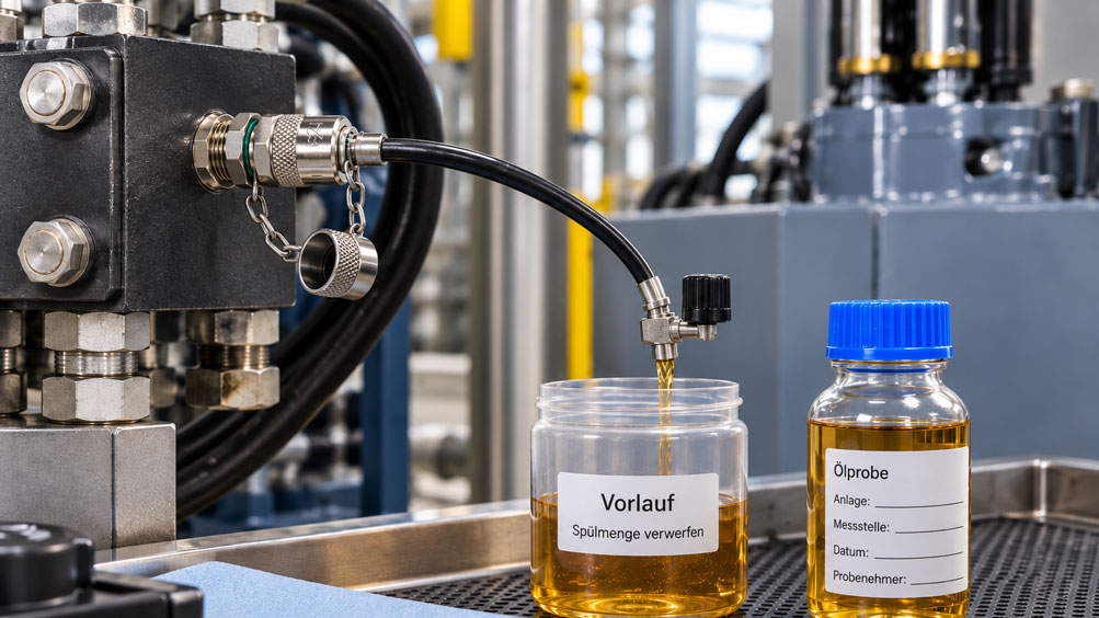
A permanently installed MINIMESS test point offers a significant advantage for sampling. It provides defined access to the operating hydraulic system without having to open a pipe fitting for every sample. Using a suitable MINIMESS hose, the oil can be routed in a controlled manner from the selected sampling point to the sample bottle.
However, the test point alone does not make the sample representative. The location of the test point, the operating condition of the machine, the flush volume, the cleanliness of the hose and sampling container, and a reproducible procedure are all decisive.
The flush volume in particular is often oversimplified. A blanket instruction such as “let 100 ml run off” is not technically appropriate for every system. Before taking the actual sample, the oil contained in the test point, adapters and connected hose, or which has remained there since the previous sampling, must first be removed.
The amount of oil required depends on the sampling system and the procedure used. Published industrial sampling instructions specify flush volumes ranging from several hundred milliliters to approximately one liter for suitable sampling valves. For unsuitable or unknown sampling valves, considerably larger flushing volumes may sometimes be required.
For recurring condition monitoring, flushing should therefore not be performed by feel each time. A defined sampling procedure should specify the sampling point, operating condition, flush volume, hose, bottle type and sample volume.
The key point is: A good oil sample does not begin in the laboratory, but at the machine. The MINIMESS test point provides clean and reproducible access to the system – but the sample only becomes representative through the correct sampling point, sufficient flushing and consistently clean working practices.
Table of Contents
- Why sampling determines the laboratory result
- Why MINIMESS is suitable for oil sampling
- Selecting the correct sampling point
- Why the system should be in a representative operating condition during sampling
- What does flush volume mean?
- Why there is no universal flush volume
- Consider the hose and adapters as dead volume
- Use the correct sample bottle
- Should the sample bottle be rinsed or not?
- How to take an oil sample via MINIMESS step by step
- Why the bottle should not be completely filled
- Safely route high-pressure oil to the sample bottle
- Consider seals and media compatibility
- Special considerations for particle counting and cleanliness classes
- Why samples should always be taken from the same sampling point
- Sample before or after the filter?
- Why a reservoir sample provides different information
- Clearly document the sample
- Systematically identify typical sampling errors
- Understanding ISO 4021 and the current standards situation
- Suitable MINIMESS components from ICS Schneider
- Conclusion
- Frequently asked questions about oil sampling via MINIMESS
1. Why sampling determines the laboratory result
In an oil condition analysis, only a comparatively small quantity of fluid is examined. However, this sample is intended to provide information about many liters or even several hundred liters of hydraulic oil throughout the entire system.
For this conclusion to be valid, the fluid taken must represent the condition of the oil at the defined sampling point as accurately as possible.
Additional contamination during sampling immediately results in a poorer measurement result. Automatic particle counting is particularly sensitive. Dust from the surroundings, fibers from a cleaning cloth or residues in a hose are not distinguished by the particle counter from actual system contamination.
Old oil that has remained in a branch line or sampling hose for an extended period is equally problematic. Its particle distribution, temperature and possibly its water content may no longer correspond to the current condition of the circulating system oil.
The quality of the laboratory cannot correct these errors afterwards. The laboratory reliably analyzes the oil contained in the bottle – regardless of whether that oil was actually representative of the system.
2. Why MINIMESS is suitable for oil sampling
A MINIMESS test point is a mechanically actuated system access point. Without the matching coupling connected, the test point remains closed.
When a suitable MINIMESS mating coupling is connected, the internal valve element is opened. This creates defined access to the medium.
The test point can therefore be used not only for pressure measurement, but also for venting, filling, draining and sampling.
A major advantage is that the sampling point remains permanently installed. The same location can be used for every recurring oil analysis without having to open a process fitting again.
This simultaneously reduces the risk of introducing dirt into the hydraulic system through assembly work.
Using a suitable MINIMESS microbore hose, the oil can then be routed in a controlled manner to a suitable sample bottle or analysis system.
3. Selecting the correct sampling point
Not every accessible point in a hydraulic system provides the same information.
For a representative examination of the circulating fluid, a sample from a flowing main line is generally more meaningful than oil from a stagnant dead zone.
ISO 4021 therefore describes sampling from a main flow line of an operating system as the preferred method for investigating particulate contamination. A reservoir sample is an alternative when no suitable sampling point is available.
The optimum location also depends on the question that is to be answered.
| Objective of the investigation | Recommended sampling-point strategy | What is being assessed? |
|---|---|---|
| General condition of the circulating system oil | Defined, well-flowing system line | Representative condition at this operating point |
| Evaluate filter performance | Sampling points upstream and downstream of the filter | Difference between contaminated and clean side |
| Assess cleanliness of the supply to a sensitive component | Line to the component | Fluid actually supplied to the component |
| Investigate wear in a specific section of the system | Return line downstream of the relevant section | Oil returning from the component or circuit |
| Assess reservoir contents | Targeted reservoir sample | Condition of the oil in the reservoir, not necessarily identical to the main flow |
The sampling point should therefore be defined when the condition-monitoring concept is established and should not be changed arbitrarily later.
4. Why the system should be in a representative operating condition during sampling
An oil sample should not represent just any condition of the system, but a defined and comparable operating condition.
After an extended shutdown, particles may have settled, air bubbles may have accumulated and temperature gradients may have developed. A sample taken immediately after start-up can therefore look different from a sample taken during normal continuous operation.
For contamination investigations, various established sampling procedures therefore recommend operating the system for a sufficient period before sampling so that the fluid is distributed throughout the system and the desired stable operating condition is reached.
General guidance often mentions an operating period of approximately 30 minutes. However, this time is not a universal constant for every machine. A small test bench may stabilize much faster, while a large hydraulic system may require more time.
For trend analysis, it is more important that recurring samples are taken under operating conditions that are as comparable as possible.
5. What does flush volume mean?
The flush volume is the fluid that is initially discarded or collected separately after opening the sampling point before the actual sample bottle is filled.
This flushing serves an important purpose: It displaces the medium and possible contaminants from the sampling path.
Depending on the setup, this includes the internal volume of the test point, mating coupling, adapters and connected hose.
At a sampling point that is rarely used, deposits or oil that no longer represents the current condition of the system may also be present in these areas.
The actual sample should only be taken once this area has been sufficiently flushed with fresh system oil.
6. Why there is no universal flush volume
The frequently asked question “How much oil should I let run off first?” cannot be answered with a single value that applies to every system.
Different established sampling procedures already specify different values for suitable sampling valves. Depending on the procedure, flush volumes ranging from several hundred milliliters to at least approximately one liter may be used.
For less suitable valves or valves with unknown particle-release characteristics, significantly larger flushing volumes may sometimes be required.
These differences demonstrate that the flush volume must not be considered in isolation.
It depends, among other things, on hose length, hose cross-section, additional adapters, test-point design, frequency of use, intended analysis and the defined sampling method.
A useful basic principle is therefore: The entire sampling path should have been exchanged several times with current system fluid before the analysis sample enters the bottle.
For recurring condition monitoring, a fixed operational flush volume should therefore be defined and then used consistently for every sampling operation.
7. Consider the hose and adapters as dead volume
A MINIMESS DN2 hose has a small internal volume. Nevertheless, this volume should not be completely ignored during a cleanliness analysis.
It is also not only the fluid volume inside the hose that matters. The internal surface can also carry particles or residual oil from previous applications.
It is particularly problematic to use the same mobile sampling hose successively on different machines with different oils without a defined cleaning and flushing procedure.
For regular trend analyses, a dedicated or clearly cleaned sampling hose is therefore advantageous.
Additional adapters should also be reduced to the necessary minimum. Every additional internal volume increases the volume that must be flushed and provides additional surfaces on which residues may remain.
The hose material, fittings, operating pressure, temperature and medium must also be compatible with one another.
8. Use the correct sample bottle
For particle counting, the cleanliness of the sample bottle itself is part of the measurement system.
An ordinary beverage bottle or arbitrary workshop container is therefore unsuitable.
Sample containers with defined cleanliness, or cleanliness appropriate to the intended analysis, and a securely closing cap should be used.
The bottle should remain closed until immediately before sampling.
When opening it, the inside of the cap, bottle neck and interior must not come into contact with fingers, cleaning cloths or contaminated surfaces.
After filling, the bottle should be closed again immediately.
Especially in very clean hydraulic systems, contamination from an unsuitable bottle can be greater than the actual particle contamination of the system.
9. Should the sample bottle be rinsed or not?
There are different recognized procedures regarding pre-rinsing of the sample bottle.
Some sampling instructions require the bottle to be partially filled one or more times with system oil, closed, agitated and the rinsing oil then discarded.
Other procedures use certified pre-cleaned sampling containers and explicitly specify that the bottle should not be rinsed with the first quantity of system oil.
For this reason, different procedures should not be combined into one general rule.
The operating instruction of the analysis laboratory or the selected sampling procedure is decisive.
Above all, a trend-monitoring program should not rinse the bottle during one sampling event and then use a different procedure at the next. A consistent sampling method improves the comparability of the results.
10. How to take an oil sample via MINIMESS step by step
Before sampling, first check whether the selected MINIMESS test point actually represents the required system position and whether pressure, temperature, medium, hose and fittings are suitable for the procedure.
The system is brought into the operating condition defined for condition assessment. For recurring trend samples, this condition should be as comparable as possible with previous sampling events.
The area around the dust cap and connection point is cleaned of external dirt without introducing contamination into the test point.
The suitable sampling hose is then connected.
The oil that initially exits is not routed directly into the analysis bottle, but is collected separately as the defined flush volume. During this process, the sample flow should remain as continuous as possible.
After sufficient flushing, the prepared sample bottle is opened only immediately before filling.
The actual sample is filled without allowing the hose end to touch the inside of the bottle or the bottle neck.
Once the specified fill level has been reached, the bottle is closed immediately.
The sample flow is then stopped, or the MINIMESS hose is disconnected according to the intended coupling procedure, and the test point is fitted with its protective cap again.
Finally, the sample and accompanying data are clearly identified.
11. Why the bottle should not be completely filled
For many oil and particle analyses, the sample bottle is intentionally not filled to the top.
A free headspace allows the sample to be homogenized again before analysis.
Particles settle during storage and transport. Before particle counting, the fluid must therefore be prepared or homogenized again according to the laboratory procedure.
Common sampling procedures often specify filling approximately three quarters to around 80% of the bottle volume.
However, the specific fill level depends on the requirements of the laboratory and the intended analysis.
An unnecessarily large air volume is not automatically advantageous either, particularly if oxidation or other oil-chemical properties are also to be examined.
12. Safely route high-pressure oil to the sample bottle
The fact that a MINIMESS test point can be connected under system pressure does not mean that hydraulic oil should be discharged directly from full line pressure into an open laboratory bottle.
There is an important difference between the permissible operating pressure of the coupling and the safe sampling pressure at the hose outlet.
Pressurized fluid can spray uncontrollably, knock over the sample bottle and create a risk of injury. With hot oil, temperature also presents an additional hazard.
For samples taken from high-pressure lines, a sampling setup specifically designed for this purpose must therefore be used to reduce flow and pressure to a safe level in a controlled manner.
Although microbore hoses limit the volumetric flow because of their small cross-section, they do not replace a risk assessment or any required pressure reduction.
The hose, coupling, adapter and, where applicable, restrictor components must be rated for the maximum system pressure and medium temperature that can occur.
13. Consider seals and media compatibility
MINIMESS test points are available with different sealing materials.
Depending on the version, classic product series use materials such as NBR, FKM or EPDM.
These materials are not equally suitable for every medium.
NBR or FKM is often used for conventional mineral-oil hydraulics. Water-glycol fluids, synthetic media or special fluids may require a different material selection.
A chemically unsuitable seal can swell, become brittle or lose its sealing function.
For recurring oil sampling, attention should therefore not be limited to the thread size of the coupling. Seal material, temperature range and medium are also part of the system design.
14. Special considerations for particle counting and cleanliness classes
Automatic particle counting detects very small solid particles and evaluates them according to size classes.
The method is therefore particularly sensitive to external contamination introduced during sampling.
An apparently poor ISO cleanliness code may be caused by actual wear or inadequate filtration – but it can also be caused by a contaminated bottle, an insufficiently flushed hose or an unsuitable sampling point.
If an unexpectedly poor result is obtained, a filter change or extensive system flushing should therefore not be initiated immediately.
It should first be checked whether the sampling point and sampling procedure were unchanged and whether the result can be confirmed by a professionally repeated sample.
ISO 11500 is relevant for automatic particle counting from bottle samples. It describes the determination of particulate contamination in a liquid sample using an automatic particle counter based on the light-extinction principle.
15. Why samples should always be taken from the same sampling point
For condition monitoring, the trend is often more important than a single absolute laboratory value.
An increase in particle count, rising wear-metal concentrations or changing water content can indicate the beginning of a change within the system.
However, a trend is only reliable if the individual samples are comparable.
If one sample is taken from the return line today, the next from the reservoir and another later from a pressure line, not only do the oil values change, but the meaning of the sampling point changes as well.
Fixed sampling points should therefore be defined and clearly identified for each system.
A permanently installed MINIMESS test point makes exactly this repeatability easier to achieve.
In addition to the sampling point, the operating condition, oil temperature and sampling procedure should also be kept as consistent as possible or documented.
16. Sample before or after the filter?
Whether a sample should be taken upstream or downstream of a filter depends on the intended information.
A sample on the upstream side shows the particle contamination being supplied to the filter. It can, for example, provide information about wear and contamination entering from the system.
A sample on the downstream side, on the other hand, shows the cleanliness actually supplied to the downstream circuit.
Two permanently defined sampling points can therefore be useful when evaluating filter performance.
However, the results must not subsequently be confused with one another.
A very clean value downstream of the filter does not mean that hardly any wear particles are being generated upstream. Conversely, a contaminated upstream sample does not automatically prove that downstream consumers are being supplied with the same contamination level.
The sampling report should therefore always state the exact location from which the sample was taken.
17. Why a reservoir sample provides different information
A reservoir sample is not fundamentally worthless, but it answers a different question from a sample taken from a flowing line.
Different flow conditions exist in the reservoir. Larger particles can settle, while lighter contaminants or air may preferentially occur in other areas.
The insertion depth of a sampling hose also influences the result.
For this reason, ISO 4021 prefers sampling from a main flow line when investigating particulate contamination. Sampling from the reservoir is considered an alternative when no suitable sampling point is available.
For recurring laboratory analyses, a well-positioned MINIMESS test point in a suitable line is therefore often more reproducible than a sample taken manually from the reservoir each time.
18. Clearly document the sample
A laboratory value without clear identification loses much of its usefulness.
At minimum, the machine or system, sampling point, date, operating hours and oil used should be clearly documented.
For detailed trend analysis, oil temperature, operating condition, filter condition, time of the last oil change or top-up and any special events are also useful.
Changes to the sampling method should also be included in the documentation.
If, for example, a different hose was used for the first time or the flush volume was changed, this can be important when assessing an unusual result later.
If several MINIMESS test points are installed on the same system, the sampling points should be clearly identified so that upstream side, downstream side, pressure line and return line are not confused.
19. Systematically identify typical sampling errors
| Observation | Possible cause | Recommended check |
|---|---|---|
| Particle value suddenly significantly worse than before | Actual contamination or contaminated sampling procedure | Repeat sampling professionally under identical conditions |
| First sample poor, immediately following sample significantly cleaner | Sampling point or hose not sufficiently flushed | Check flush volume and dead volume |
| Results fluctuate strongly from one sampling date to another | Different sampling points or operating conditions | Standardize the sampling procedure |
| Sample contains visible air bubbles | Excessive pressure reduction, unsuitable sample flow or air ingress in the system | Check sampling pressure and system condition |
| Sample is significantly colder than the current system oil | Stagnant oil from a long sampling line | Flush the sampling path for longer |
| Values change abruptly after changing the sampling hose | Hose contamination or residual foreign oil | Check hose assignment and cleaning procedure |
| Cleanliness value downstream of filter very good, upstream value conspicuous | Can be a normal filter effect | Clearly assign sampling points and maintain separate trends |
| Reservoir sample and line sample differ significantly | Different sampling locations and flow conditions | Do not directly equate them; consider the meaning of the respective sampling point |
20. Understanding ISO 4021 and the current standards situation
ISO 4021 is a central technical reference for taking hydraulic fluid samples from lines in an operating system.
The currently published edition is ISO 4021:1992. It has most recently been confirmed and describes sampling for the analysis of particulate contamination.
The central principle remains current: A sample should preferably be taken from a main flow line in such a way that the particulate contamination of the sample represents the fluid at the sampling point.
In 2026, a new edition is being revised as ISO/DIS 4021. The draft is intended to replace the 1992 edition, but at the present time it is not yet the published successor standard.
ISO 11500 is additionally relevant for the actual automatic particle counting of liquid samples.
For operational work instructions, the requirements of the analysis laboratory, machine manufacturer and the sampling or analysis equipment used should also be taken into account.
21. Suitable MINIMESS components from ICS Schneider
ICS Schneider Messtechnik offers MINIMESS test points, microbore hoses, adapters and accessories for pressure measurement, diagnostics, filling, venting and sampling. An overview can be found under MINIMESS Couplings and Hoses.
21.1 MINIMESS 1620
The MINIMESS 1620 is the classic standard series with an M16 × 2 coupling thread.
The test point is designed as a mechanically actuated system access point for analysis and testing tasks and enables, among other things, pressure monitoring, venting, filling, draining and sampling during operation of the hydraulic system.
Depending on the version, different process connections, materials and sealing materials are available.
The series is available for operating pressures of up to 630 bar. This pressure specification describes the load capacity of the suitable test point and does not mean that an open sample bottle may be exposed to this pressure.
21.2 MINIMESS 1215
The MINIMESS 1215 provides the same basic operating principle in a particularly compact design.
This series is also designed for sampling, pressure monitoring, filling, draining and venting and is particularly suitable where installation space is limited.
21.3 MINIMESS 1604
The MINIMESS 1604 has a larger free cross-section with DN4 and is particularly designed for faster filling and draining.
Sampling is also possible. However, when taking an oil sample, it must be taken into account that the larger cross-section can produce a different sample flow from a typical DN2 microbore line.
21.4 MINIMESS Hoses
The MINIMESS hoses are available in different DN2 and DN4 versions.
They are used not only for pressure transmission to pressure gauges and sensors, but also for venting and direct sampling from the system.
Depending on the version, different hose materials, fittings, pressure ratings and temperature ranges are available.
For oil sampling, a configuration should be selected that matches the medium, system pressure, temperature range and desired sample flow.
21.5 Application Engineering by ICS Schneider
For configuring a suitable sampling solution, relevant information includes the existing MINIMESS series, process thread, maximum system pressure, oil type, temperature, required hose length and sampling procedure.
It should also be known whether a conventional laboratory sample is to be taken, a portable particle counter is to be connected or a permanently installed online analysis system is to be implemented.
22. Conclusion
A MINIMESS measuring point provides excellent conditions for reproducible oil sampling because the same defined system access point can be used for every analysis.
However, the quality of the sample does not depend on the coupling alone.
The most important requirement is a suitable sampling point in an area where the oil condition actually represents the question being investigated.
Before taking the actual sample, the test point, adapters and hose must be sufficiently flushed with current system fluid. There is no universal flush volume that is equally correct for every machine and every sampling system.
The flush volume must match the dead volume and the defined procedure. For recurring analyses, it should be documented and then used consistently.
The cleanliness of the sample bottle is equally important. Especially for particle counting, a single contaminated component can influence the result more strongly than the actual change in the hydraulic oil.
The operating condition of the system must also be reproducible. A sample taken from a warm, operating system cannot automatically be compared with one taken immediately after an extended shutdown.
For high-pressure systems, safety must also be taken into account. The permissible pressure rating of the MINIMESS test point must not be confused with a permissible open sampling pressure. The oil flow must be reduced to a suitable level in a controlled and safe manner.
For reliable oil condition monitoring, the following sequence therefore applies:
Define a representative sampling point → bring the system into a defined operating condition → keep the sampling area clean → connect a suitable MINIMESS hose → flush the defined volume → fill a clean sample bottle according to the specified procedure → close it immediately → document the sampling point and operating data → always compare results using the same sampling strategy.
Standardizing this procedure significantly increases the value of every laboratory analysis. The question is then no longer whether an unusual result may have been caused by the sampling process, but whether the condition of the machine has actually changed.
23. Frequently asked questions about oil sampling via MINIMESS
23.1 Can I take an oil sample through a MINIMESS test point?
Yes. Classic MINIMESS test points are explicitly designed for sampling from fluid-power systems as well.
23.2 Can the sample be taken while the system is operating?
With an appropriately rated test point and a safe sampling setup, sampling during operation is possible and is often advantageous for obtaining a representative sample from the main flow.
23.3 How much oil should I flush before taking the sample?
There is no single universal value. The required flush volume depends on the test point, hose, adapters and the sampling procedure used. Published procedures specify values ranging from several hundred milliliters to at least approximately one liter for suitable sampling points.
23.4 Is it sufficient to flush the internal hose volume once?
Not necessarily. In addition to the pure hose volume, the test point, mating coupling, adapters and possible deposits or stagnant oil must also be taken into account.
23.5 Can I always use the same MINIMESS hose for different oils?
Technically, repeated use is possible, but it can cause cross-contamination between different systems. For reproducible laboratory analyses, a defined cleaning procedure or dedicated hose assignment is required.
23.6 Does the sample bottle need to be rinsed beforehand?
This depends on the sampling procedure used and the laboratory requirements. Some procedures require rinsing with system oil, while others use pre-cleaned bottles and intentionally avoid rinsing. The procedure should not change within a trend-monitoring program.
23.7 Why should the bottle not be completely filled?
A defined headspace makes subsequent homogenization of the sample easier for many analysis methods. A fill level of approximately 75 to 80% is frequently used. The requirements of the analysis laboratory remain decisive.
23.8 May I place the inside of the cap on a surface?
Contamination of the inside should be avoided. The cap and bottle opening must not come into contact with hands, the workbench, cleaning cloths or other potentially contaminated surfaces.
23.9 Is a sample taken directly from the reservoir just as good?
Not necessarily. For particulate contamination, a representative sample from a flowing main line is preferred. A reservoir sample can reflect different flow and sedimentation conditions.
23.10 Should I take the sample before or after the filter?
This depends on the question being investigated. Upstream of the filter, the incoming contamination can be assessed; downstream of the filter, the oil cleanliness actually supplied to the downstream circuit can be evaluated.
23.11 Can I directly compare the two results?
Yes, if the filter performance is specifically being investigated. For long-term condition trends, however, upstream and downstream sampling points should be maintained as separate measurement series.
23.12 Why should the machine be running before sampling?
This allows the oil to circulate throughout the system and particles to be captured under the intended operating condition. After an extended shutdown, sedimentation and temperature differences can alter the result.
23.13 Does the system always have to run for exactly 30 minutes?
No. Approximately 30 minutes is mentioned in various general sampling procedures but is not a universal requirement for every machine. The decisive factor is a defined, representative operating condition that is comparable between repeated samples.
23.14 Can I discharge an oil sample directly from a 300-bar line into the bottle?
Not in an uncontrolled manner. A test point suitable for high system pressure does not mean that an open bottle or the operator may be exposed to this pressure. The sample flow must be depressurized in a controlled manner using a suitable setup.
23.15 Is a DN2 hose suitable for oil sampling?
MINIMESS DN2 microbore hoses can be used for sampling. However, the specific hose and fitting configuration must be suitable for the medium, pressure and temperature range.
23.16 Can insufficient flushing worsen the ISO cleanliness code?
Yes. Residues and particles in the sampling path can enter the bottle and falsely indicate a higher contamination level.
23.17 Can an oil sample also appear too clean?
Yes. A non-representative sampling point, such as a quiet area where sedimentation occurs, can show a different particle contamination level from the fluid actually flowing through the relevant section of the system.
23.18 Why should the same test point always be used?
Only then can successive laboratory values be meaningfully compared as a trend. Different sampling points can represent different conditions within the same system.
23.19 Which standard covers sampling from hydraulic lines?
ISO 4021 covers taking fluid samples from the lines of an operating hydraulic system for analysis of particulate contamination. ISO 4021:1992 is currently still the published edition; a new edition is undergoing standardization in 2026.
23.20 Which standard is relevant for automatic particle counting from a bottle sample?
ISO 11500 describes the determination of particulate contamination in a liquid sample using an automatic particle counter based on the light-extinction principle.
23.21 Which MINIMESS series is suitable for sampling?
Several classic MINIMESS series such as 1215, 1615, 1620 and 1604 can generally be used for sampling. Selection depends on the existing coupling system, pressure, available installation space, required flow rate and process connection.
23.22 What information does ICS Schneider require for a sampling setup?
Useful information includes the existing MINIMESS series or coupling thread, system pressure, oil type, minimum and maximum temperature, required hose length, existing process connection and whether a laboratory bottle, portable particle counter or another analysis device is to be connected.