


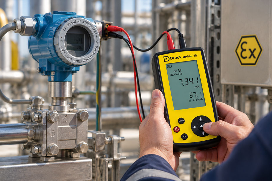
A 2-wire transmitter has only two electrical connection wires. These same two wires supply the field device with power while simultaneously transmitting its measured value as a 4–20 mA current signal. This simple and robust technology is one of the reasons why 2-wire transmitters are so widely used in the process industry.
When testing with a process or loop calibrator, however, this principle often causes confusion. Modern calibrators can measure current, actively source current, simulate a loop-powered transmitter and provide their own 24 V loop supply. These functions may look similar on the display, but electrically they perform completely different tasks.
Anyone wishing to test an existing 2-wire transmitter must measure its actual output current while also ensuring that the transmitter is supplied with sufficient power. If, on the other hand, only the PLC input is to be tested, the real transmitter is often removed from the measurement loop and replaced by a defined mA signal from the calibrator.
The term “simulation” is also not unambiguous. A process calibrator can, for example, simulate a Pt100 to test the input of a temperature transmitter. It can also simulate a complete 2-wire transmitter and behave like a current-regulating field device within an existing 24 V current loop. These are two completely different test tasks.
Loop power must also be considered. A loop-powered 2-wire transmitter cannot generate a valid 4–20 mA current without a supply voltage. On the workbench, the calibrator’s integrated 24 V loop-power function is therefore often required. In an operating plant, however, the loop may already be powered by a PLC, an isolating power supply or a separate power supply.
If it is not first established which power supply is already present, two active voltage sources can be connected against each other, or a current loop that is actually passive may remain completely unpowered.
The key point is: To test a 2-wire transmitter, its output current is measured while the transmitter is supplied correctly at the same time. “Sourcing mA” and “simulating a transmitter”, by contrast, primarily test the downstream current loop or PLC input – not the actual transmitter.
Table of Contents
- How does a 2-wire transmitter work?
- Distinguishing measuring, sourcing, simulating and loop power
- When is mA measured?
- When is the 24 V loop supply required?
- What does mA Source or sourcing current mean?
- What does mA Simulation or Sink mean?
- Do not confuse sensor simulation with transmitter simulation
- The correct test setup for a 2-wire transmitter
- Why an input signal is also required for calibration
- How to perform a 5-point test correctly
- How to calculate measurement deviation correctly
- Check available loop voltage and load
- Using HART and a 250 Ω resistor correctly
- Test the transmitter and PLC input separately
- Choose stabilization and measurement time correctly
- Consider the measurement uncertainty of the complete test
- Document as-found and as-left conditions traceably
- Systematically diagnose typical faults
- Suitable calibration equipment from ICS Schneider
- Conclusion
- Frequently asked questions about testing 2-wire transmitters
1. How does a 2-wire transmitter work?
With a 2-wire transmitter, the same two conductors are used both to power the field device and to transmit the measurement signal.
A typical current loop consists of a DC power supply, the 2-wire transmitter, an analog input of the PLC or control system, and the connecting cables. All components are electrically connected in series. The same loop current therefore flows through all elements.
The transmitter regulates this current according to its process measured value. With a linear 4–20 mA signal, 4 mA typically corresponds to the lower range value and 20 mA to the upper range value.
A pressure transmitter with a range of 0 … 10 bar, for example, ideally outputs 4 mA at 0 bar, 12 mA at 5 bar and 20 mA at 10 bar.
The transmitter normally does not generate its own supply voltage. It draws the energy required for operation from the current loop while simultaneously regulating the loop current.
This characteristic must be taken into account when connecting a calibrator. A removed 2-wire transmitter will only operate on the workbench if a suitable loop supply is available.
2. Distinguishing measuring, sourcing, simulating and loop power
A modern process calibrator can provide several current functions that are not electrically equivalent.
| Function | What does the calibrator do? | Typical application |
|---|---|---|
| Measure mA | Measures the actual current present in a current loop | Check the output of a real transmitter |
| mA Source | Actively generates a defined current | Test a passive PLC input, display or controller |
| mA Simulate / Sink | Regulates the current in an externally powered loop like a 2-wire transmitter | Replace the real transmitter and test the existing current loop |
| 24 V Loop Power + mA measurement | Powers the 2-wire transmitter and simultaneously measures its current | Test a transmitter on the workbench or without plant power |
| Simulate RTD / TC / Ω / mV | Generates an input signal for a transmitter | Test the input and transfer function of a temperature transmitter |
Selecting the correct operating mode therefore starts with the test task, not with the calibrator.
The first question is: Is the existing transmitter to be tested, or is the calibrator intended to replace the transmitter?
The second question is: Is a loop supply already present?
Only then should the appropriate calibrator function be selected.
3. When is mA measured?
The mA measurement function is used when the actual output current of an existing transmitter is to be determined.
Since the same current flows through all series-connected components in a current loop, the current calibrator is normally inserted into the loop in series as well.
For this purpose, an existing current loop must be opened at a suitable point and then closed again through the calibrator’s mA measurement input.
A current meter must not simply be connected in parallel across the 2-wire transmitter like a voltage meter. The mA input has a much lower internal resistance and would therefore significantly alter the circuit or, in the worst case, effectively short-circuit it.
If the system is already powered by a 24 V supply, an isolating power supply or an active PLC input, the calibrator does not require an additional loop-power function for this pure current measurement.
It simply measures the current that the actual transmitter sets in the existing loop.
4. When is the 24 V loop supply required?
When a 2-wire transmitter is tested outside the plant, the electrical power supply that would normally be provided by the installation is often missing.
A process or loop calibrator with an integrated loop supply can provide this function.
In Loop Power mode, the calibrator typically supplies a nominal DC voltage to the current loop while simultaneously measuring the current regulated by the transmitter.
This creates a complete small 4–20 mA current loop on the workbench consisting of the calibrator and the device under test.
This operating mode is particularly convenient because no separate 24 V power supply is required.
However, it must not additionally be enabled if the current loop is already being powered by another active device, unless the specific calibrator and test setup explicitly allow this.
Two voltage sources in the same loop can result in incorrect readings, protective shutdowns or impermissible electrical loading.
5. What does mA Source or sourcing current mean?
In Source mode, the calibrator itself generates a defined current.
It therefore does not behave like a 2-wire transmitter under test, but rather as an active current source.
This operating mode is particularly suitable for testing a passive analog input.
If, for example, a passive PLC input is supplied with 4.000 mA, 12.000 mA and 20.000 mA, it can be checked whether the PLC correctly calculates 0%, 50% and 100% from these values.
The actual process sensor and the actual transmitter are not involved in this test.
A correct PLC reading therefore only proves that the input card, wiring and scaling from the injection point onward are functioning correctly.
If, however, the PLC input itself provides loop power, it must be checked before using Source mode whether an active current source may be connected at all. In an already powered loop, Simulate or Sink mode is often the correct choice.
6. What does mA Simulation or Sink mean?
In Simulate or Sink mode, the calibrator behaves electrically in a similar way to a loop-powered 2-wire transmitter.
The calibrator does not provide the loop voltage itself. An external voltage source powers the circuit while the calibrator regulates the current to the desired value.
This allows the actual transmitter to be removed or electrically disconnected from the system and replaced by the calibrator.
The existing plant power supply, wiring, isolation barrier, display and PLC input remain part of the test.
If, for example, 4, 12 and 20 mA are simulated and the PLC displays the expected values, the fault is very unlikely to be located in this part of the current loop.
However, transmitter simulation does not test the removed or bypassed transmitter.
This distinction is essential for troubleshooting.
7. Do not confuse sensor simulation with transmitter simulation
The term simulation is used for two fundamentally different processes with process calibrators.
In sensor simulation, the calibrator generates an input signal for the transmitter.
For a Pt100 temperature transmitter, for example, a defined resistance can be simulated. For a thermocouple transmitter, the calibrator generates a defined thermoelectric voltage including the intended cold-junction handling.
The real transmitter remains the device under test. Its 4–20 mA output is then measured and compared with the simulated sensor input.
With transmitter simulation, the opposite takes place. The real transmitter is removed from the signal path and the calibrator assumes its electrical role within the 4–20 mA loop.
In this case, it is no longer the transmitter that is being tested, but rather the downstream measurement loop.
A multifunction process calibrator is particularly powerful when it can simultaneously simulate a sensor input and measure the mA output of the transmitter.
8. The correct test setup for a 2-wire transmitter
A complete transmitter test fundamentally requires two pieces of information: a known input value and the resulting output current.
The specific test setup therefore depends on the measuring principle.
For a pressure transmitter, a known reference pressure is applied. At the same time, the 4–20 mA current is measured.
For a temperature transmitter, a Pt100, resistance, mV or thermocouple signal can be simulated. The current output is then measured as well.
The same basic principle applies to other measured variables: The input must be applied using a sufficiently well-known reference quantity, and the output must be determined independently.
If no plant power supply is available, a suitable calibrator can also provide the loop supply at the same time.
This allows the input and output of the transmitter to be compared rather than merely checking the function of the current loop.
9. Why an input signal is also required for calibration
A common mistake is to measure only the current mA value of a transmitter and use this alone to assess its calibration.
A measured current of, for example, 12.01 mA does not by itself indicate whether the transmitter is operating correctly.
It must also be known which actual process or reference value is present at the transmitter input.
For a 0 … 100 °C temperature transmitter, 12 mA would only be correct if the input actually corresponds to exactly 50 °C.
The same applies to 5 bar for a 0 … 10 bar pressure transmitter.
A complete calibration therefore always compares the known transmitter input with its measured output.
A pure loop calibrator can check the electrical output very effectively. For a complete process calibration, however, a suitable reference or input simulation is additionally required.
10. How to perform a 5-point test correctly
For a linear transmitter, a multi-point test is significantly more informative than merely checking zero and full scale.
A commonly used procedure consists of five evenly distributed test points across the measuring range.
| Process value | Ideal 4–20 mA output | Typical test |
|---|---|---|
| 0% | 4.000 mA | Lower range value / zero point |
| 25% | 8.000 mA | Lower intermediate point |
| 50% | 12.000 mA | Mid-range point |
| 75% | 16.000 mA | Upper intermediate point |
| 100% | 20.000 mA | Upper range value / span |
For measured variables where hysteresis may occur, it is useful to approach the test points not only in the increasing direction but also subsequently in the decreasing direction.
At each point, sufficient time must first be allowed for the input signal and transmitter output to stabilize.
Only then should the mA value be documented.
The test points and permissible deviations should be defined before calibration begins. This prevents the assessment criteria from being adjusted only after the result is known.
11. How to calculate measurement deviation correctly
For a linear 4–20 mA transmitter, the theoretical output current can be calculated from the relative input value.
In simplified form:
Iexpected = 4 mA + 16 mA × process fraction
For a process fraction of 50%, this gives:
Iexpected = 4 mA + 16 mA × 0.5 = 12 mA
The current deviation is calculated as:
ΔI = Imeasured − Iexpected
Depending on the test plan, this deviation can then be stated in mA, as a percentage of the 16 mA output span, or converted back into the physical process unit.
The selected form of representation should be used consistently for all test points.
For transmitters with a non-linear output function, characteristic correction or special scaling, the simple linear relationship must not be used without verification.
12. Check available loop voltage and load
A 2-wire transmitter requires a certain minimum voltage at its terminals so that its electronics can operate correctly and regulate the required loop current.
However, the full 24 V supply voltage is not automatically available at the transmitter.
The PLC input, cable resistance, isolating power supplies, Ex barriers, displays and, where applicable, a HART resistor all cause additional voltage drops.
For purely resistive loads:
U = I × R
A resistance of 250 Ω already causes a voltage drop of 5 V at 20 mA.
For a reliable current loop, the following simplified condition must therefore be met:
Usupply ≥ Utransmitter,min + Uloads + Ucable
Testing at high output currents is particularly important because the voltage drop across resistive loads increases with current.
A loop can therefore appear to function correctly at 4 mA but reach its limit at 20 mA because the remaining voltage margin is too small.
13. Using HART and a 250 Ω resistor correctly
With HART-capable 2-wire transmitters, digital communication is superimposed on the analog 4–20 mA signal.
A suitable loop impedance is required for reliable HART communication. In many test setups, a resistor of approximately 250 Ω is used for this purpose.
Some process calibrators have an internally switchable HART resistor.
If a suitable external resistor or sufficient loop impedance is already present, an additional 250 Ω resistor should not be switched in without checking the circuit.
Every additional resistance increases the electrical load of the loop and reduces the voltage available at the transmitter.
With an intelligent HART transmitter, the test can be usefully extended: In addition to the analog output current, the process value, LRV, URV, unit, damping and diagnostic status can be checked digitally.
However, the HART signal does not replace the analog test. A digitally correct process value does not prove that the 4–20 mA output is also correctly scaled.
14. Test the transmitter and PLC input separately
Systematic troubleshooting separates the measurement chain into individual sections.
The actual transmitter can be tested first. For this purpose, a defined input value is applied, the transmitter is powered and its actual current is measured.
If this output is correct but the PLC displays an incorrect process value, the cause is probably located downstream of the transmitter.
The transmitter can then be electrically disconnected and the PLC input tested with the calibrator.
For a passive input, the calibrator can, for example, actively source defined currents. In an already powered 2-wire loop, the calibrator can simulate the transmitter in Sink mode.
If the PLC correctly displays 0%, 50% and 100% at 4, 12 and 20 mA, the analog input and scaling are fundamentally plausible.
This makes it possible to distinguish whether the fault lies in the sensor or transmitter, the current loop, or the PLC evaluation.
15. Choose stabilization and measurement time correctly
A process calibrator can capture electrical values very quickly. However, the process sensor under test may respond significantly more slowly.
With pressure transmitters, for example, pressure volumes, hoses and the mechanical sensing element must stabilize after a pressure change.
With temperature transmitters, the thermal stabilization of the reference sensor or calibrator often determines the required waiting time.
In addition, electronic damping may be configured in the transmitter. A high damping value deliberately causes the 4–20 mA output to respond more slowly to an input change.
If the value is documented too early, this time delay can incorrectly be interpreted as a calibration deviation.
A defined stability criterion or sufficient waiting time should therefore be used before recording each measured value.
16. Consider the measurement uncertainty of the complete test
The accuracy of the process calibrator’s mA input is only one part of the total test uncertainty.
For a pressure transmitter, for example, the pressure reference, pressure generation, stability, temperature and, where applicable, height differences between the reference and device under test must also be considered.
For a temperature transmitter, resistance or thermocouple simulation, wiring configuration, cold junction and, where applicable, external reference sensors influence the result.
The transmitter under test also has its own specification, which may vary depending on temperature range, turndown and operating conditions.
For a reliable calibration decision, the suitability of the complete reference chain for the required tolerance must therefore be assessed.
A highly accurate mA calibrator alone cannot turn an inadequate process reference into a high-quality transmitter calibration.
17. Document as-found and as-left conditions traceably
Before any adjustment is made, the original values of the transmitter should first be documented.
These so-called as-found data show how the measuring point was actually operating before the intervention.
If a transmitter is adjusted immediately after the first test point shows a deviation, important information about its previous drift or characteristic is lost.
A traceable test therefore first documents all specified as-found points.
Only then is it decided whether an adjustment is required and permissible.
After adjustment, the complete relevant test sequence is performed again. These results form the as-left condition.
Documentation should include at least identification of the device under test, measuring range, test points, reference values, measured output values, deviations, test equipment used, date and result assessment.
For digital or HART-capable devices, the device configuration and relevant parameters can additionally be documented.
18. Systematically diagnose typical faults
| Observation | Possible cause | Recommended check |
|---|---|---|
| Transmitter indicates 0 mA or no current | No supply, open loop or incorrect polarity | Check loop power, continuity and connections |
| Calibrator measures nothing although plant power is present | mA meter connected incorrectly | Check whether the mA input is actually connected in series |
| A fault occurs when Loop Power is enabled | The loop is already externally powered | Identify the existing voltage source and correct the test mode |
| PLC does not respond to mA Source | Active PLC input or existing loop supply | Check whether Simulate/Sink should be used instead |
| Transmitter operates at 4 mA but cannot reach 20 mA | Insufficient available loop voltage or excessive load | Determine voltage drops at high current |
| HART communication does not work | Missing or unsuitable loop impedance | Check HART resistor and total loop load |
| HART process value correct, analog current incorrect | Analog output incorrectly adjusted or scaled | Compare digital PV and measured mA output separately |
| Transmitter current correct, PLC value incorrect | PLC scaling, analog input or wiring | Replace transmitter and simulate or source a defined mA value |
19. Suitable calibration equipment from ICS Schneider
ICS Schneider Messtechnik offers loop, multifunction and pressure calibrators for testing 2-wire transmitters and complete 4–20 mA measurement loops. An overview can be found under Calibration Technology and Process Calibrators / Electrical Calibrators.
19.1 Druck UPS4E Loop Calibrator
The Druck UPS4E is specifically designed for testing and troubleshooting 4–20 mA current loops.
It can measure or source currents from 0 … 24 mA and provides an integrated 24 V DC loop supply.
This makes it particularly suitable for the fundamental tasks associated with 2-wire transmitters: measuring an existing loop current, powering and measuring a removed transmitter, and generating defined current values for testing downstream devices.
An integrated 250 Ω resistor supports test setups with HART communication.
Step, ramp and span functions simplify recurring 4–20 mA tests.
An intrinsically safe version is available for work in hazardous areas, provided that the entire test task and the intrinsically safe circuit are suitable for this purpose.
19.2 Druck DPI620G Multifunction Process Calibrator
The DPI620G is particularly useful when not only the 4–20 mA output but also the input of a process transmitter is to be tested with the same instrument.
The calibrator can measure and source electrical quantities and, depending on configuration, supports mA, mV, V, resistance, RTD, thermocouple and frequency, among others.
This makes it possible, for example, to apply a simulated Pt100 or thermocouple signal to a temperature transmitter while simultaneously evaluating its 4–20 mA output.
An internal 24/28 V loop supply enables operation of loop-powered transmitters without a separate power supply.
Depending on the DPI620G version, HART and other communication functions are also available. This allows analog measured values and digital device parameters to be checked together on intelligent transmitters.
19.3 Druck DPI610E / DPI610E-IS for Pressure Transmitters
For 2-wire pressure transmitters, the DPI610E / DPI610E-IS is particularly useful because pressure reference, pressure generation and electrical test functions can be combined in one portable system.
This allows a defined pressure to be generated while simultaneously checking the 4–20 mA output of the pressure transmitter.
Depending on the version, vacuum, pneumatic or hydraulic pressure generation as well as HART communication and documentation functions are available.
For a complete pressure-transmitter test, there is therefore no need to combine a separate pressure instrument, separate hand pump and separate loop calibrator.
19.4 Which calibrator is suitable for which task?
Anyone mainly testing 4–20 mA loops, troubleshooting faults or checking PLC inputs will often only require a compact loop calibrator such as the UPS4E.
If temperature transmitters, resistance, mV, frequency or other electrical process signals must also be simulated and evaluated at the same time, a multifunction process calibrator such as the DPI620G is more suitable.
For pressure transmitters, an integrated pressure calibrator such as the DPI610E can significantly simplify the complete test setup.
The decisive factor is therefore not the largest possible number of functions, but which input quantity must be generated at the transmitter and which output signal must be tested at the same time.
20. Conclusion
Testing a 2-wire transmitter is electrically straightforward once the individual functions of the calibrator are clearly distinguished from one another.
A 2-wire transmitter requires a loop voltage and regulates its 4–20 mA current within that loop.
If the real transmitter is to be tested, its actual output current must therefore be measured. If no external power supply is available, the calibrator additionally provides the loop supply.
Source mode performs a different task. In this mode, the calibrator actively generates a current and is particularly suitable for testing passive displays or analog inputs.
In Simulate or Sink mode, by contrast, the calibrator replaces a loop-powered transmitter within an externally powered current loop.
The term simulation must also be used unambiguously. A Pt100 or thermocouple simulation generates the input quantity for a transmitter. An mA transmitter simulation, on the other hand, replaces the transmitter’s output function within the current loop.
For a complete calibration, current measurement alone is not sufficient. The transmitter must be subjected to a known input quantity and its output compared against it.
In addition, the supply voltage and loop load must be sufficiently dimensioned. A 2-wire transmitter still requires enough voltage for its own electronics even at 20 mA.
With HART devices, the required loop impedance must also be taken into account. A 250 Ω resistor already causes a voltage drop of 5 V at 20 mA and must therefore be included in the voltage budget.
For a reproducible test, the following sequence therefore applies:
Define the test task → identify the existing loop supply → select the correct calibrator mode → generate the input value reproducibly → measure the output current → test several points upward and downward → check loop voltage and load → document as-found and as-left conditions.
Following this sequence avoids the most common mistake when working with process calibrators: connecting an electrically correct calibrator in the wrong operating mode and thereby confusing transmitter testing, loop testing and PLC input testing.
21. Frequently asked questions about testing 2-wire transmitters
21.1 What is a 2-wire transmitter?
A 2-wire transmitter uses the same two wires for its power supply and its 4–20 mA output signal. It is therefore powered from the current loop.
21.2 Does a 2-wire transmitter always require an external power supply?
It requires a loop voltage. This can be supplied by the plant, an isolating power supply, an active analog input or, during testing, by a calibrator with a Loop Power function.
21.3 What does mA Measure mean?
The calibrator measures the actual current present in the loop. This function is used to check the output current of a real transmitter.
21.4 Must the calibrator be connected in series when measuring current?
Yes. The current measurement path is normally inserted in series into the 4–20 mA loop.
21.5 Can I connect the mA input in parallel with the transmitter?
This should not be done for a normal current measurement. Unlike a high-impedance voltage input, a current measurement input significantly affects the loop and must be connected in series for the intended current measurement.
21.6 What does Loop Power mean?
Loop Power means that the calibrator provides the supply voltage for a loop-powered transmitter. With suitable instruments, its output current can be measured at the same time.
21.7 When do I need the Loop Power function?
Typically when testing a removed 2-wire transmitter on the workbench or when no other suitable loop supply is available at the measuring point.
21.8 What does mA Source mean?
In Source mode, the calibrator actively generates a defined current. This function is suitable, for example, for testing a passive PLC input or display.
21.9 What does mA Simulate or Sink mean?
In this mode, the calibrator regulates the current in an externally powered loop and therefore behaves electrically in a similar way to a loop-powered 2-wire transmitter.
21.10 Does Simulate mode require an external power supply?
Generally yes, if the calibrator is operating in pure Sink or transmitter-simulation mode. The loop voltage is then supplied by the plant or a separate power supply.
21.11 Am I testing the real transmitter in Simulate mode?
No. The calibrator replaces the transmitter. This primarily tests the loop supply, wiring, input card and scaling of the downstream measurement chain.
21.12 What is the difference between sensor simulation and transmitter simulation?
With sensor simulation, the calibrator generates, for example, a Pt100, resistance, mV or thermocouple signal for the input of a real transmitter. With transmitter simulation, the calibrator instead replaces the transmitter’s 4–20 mA output.
21.13 Is an mA measurement sufficient to calibrate the transmitter?
No. For a complete check, the actual or simulated input quantity must also be known. Only the comparison between a defined input and the measured output evaluates the transmitter’s transfer function.
21.14 Which mA values correspond to 0, 25, 50, 75 and 100%?
For a linear 4–20 mA characteristic, these points correspond to 4, 8, 12, 16 and 20 mA.
21.15 Why does a transmitter sometimes fail to reach 20 mA?
One possible cause is insufficient available loop voltage. High loop loads, long cables, isolating power supplies or additional resistors can consume so much voltage that the transmitter can no longer regulate the required current.
21.16 Why does the loop work at 4 mA but not at 20 mA?
The voltage drop across resistive loads increases proportionally with current. The voltage margin can therefore be sufficient at 4 mA but already too low at 20 mA.
21.17 What is the purpose of a 250 Ω resistor with HART?
It provides a suitable loop impedance for HART communication. Whether an additional resistor is required depends on the existing test setup and the loop impedance already present.
21.18 Do I still need to test the 4–20 mA signal when using HART?
Yes. The digital process value and the analog output are two different parts of the transmitter. A correct HART value does not automatically confirm a correctly adjusted 4–20 mA output.
21.19 Why are as-found values important?
They document the condition of the transmitter before adjustment. This makes it possible to assess whether and how much the measuring point has drifted since the previous test.
21.20 What information does ICS Schneider require to select a process calibrator?
Useful information includes the transmitter types to be tested, input quantities such as pressure, Pt100, thermocouple, mV or resistance, required 4–20 mA functions, required loop power, HART requirements, desired accuracy and documentation functions and, where applicable, requirements for ATEX or IECEx.