


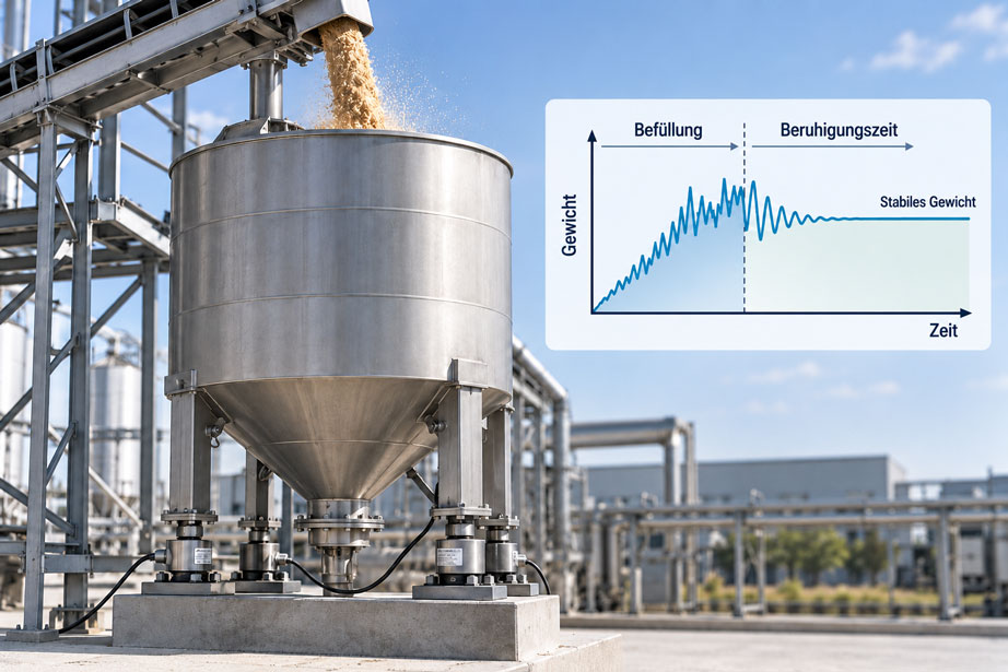
A silo mounted on load cells initially appears to be a classic static weighing system. The dead weight of the vessel and the mass of the material inside act on the load cells, whose signals are used to calculate the current total mass.
During filling, however, the situation is significantly more dynamic. The material does not immediately come completely to rest. It falls through an inlet pipe, strikes material already present or internal components, changes its direction of motion and causes the silo body to vibrate.
At this moment, the load cells do not only detect the weight force of the material that has already come to rest. Time-dependent forces from the material flow and from movement of the mechanical structure also act on them.
As a result, the weight displayed during filling may temporarily be above or below the later stable final value. A rapidly fluctuating measured value does not automatically mean that the load cells are inaccurate.
The filling technology also plays an important role. A freely falling material stream generates different dynamic forces from a slowly rotating screw conveyor. Pneumatic conveying can introduce additional vibrations and forces into the silo through inlet pipes, venting systems and connected pipework.
The measurement dynamics also do not end immediately when the material supply is switched off. Material may continue to fall from the inlet, the silo body may continue to oscillate and the bulk material may continue to settle inside the vessel.
A stable weight value can only be accepted after a sufficient settling time.
Strong digital filtering can significantly stabilize the displayed value. However, it does not eliminate mechanical disturbances. If the filtering is too strong, the scale responds so slowly that the displayed value noticeably lags behind the actual filling process.
The key point is: When weighing a silo during filling, material impact, mechanical vibrations, load-cell sizing, force shunts, signal filtering and the required settling time must be considered together. The value indicated while material is entering the silo is not automatically identical to the later static final weight.
Table of Contents
- How does a silo weighing system work?
- Why does an essentially static scale become dynamic during filling?
- How does material impact affect the weight reading?
- Why does material flow generate an additional force?
- How do vibrations occur in a silo?
- What does settling time mean?
- Use a stability criterion instead of a fixed waiting time
- Correctly coordinate signal filtering and settling time
- When is the weight value usable during filling?
- Control filling by weight and account for material in flight
- Size load cells for static and dynamic loads
- Consider load distribution between multiple load cells
- Avoid force shunts through pipework and attachments
- Design flexible connections correctly
- Consider temperature and thermal expansion
- Correctly assess pneumatic filling and pressure forces
- Correctly calibrate and test the silo scale
- Systematically diagnose typical fault patterns
- Suitable weighing technology from ICS Schneider
- Conclusion
- Frequently asked questions about weighing a silo during filling
1. How does a silo weighing system work?
With a gravimetric silo or vessel weighing system, the weight of the complete vessel is measured by load cells.
Depending on the design, the silo may stand on three or four weighing points, for example. Each of these points contains a load cell or a suitable weighing module that converts the applied force into an electrical signal.
The weighing electronics evaluate the individual signals together and determine the total load from them.
The basic weight force can be described in simplified form as:
FG = m × g
where m is the mass of the silo including its contents and g is gravitational acceleration.
To determine the actual material quantity, the empty weight or tare of the silo is first determined. The difference between gross weight and tare gives the net weight of the bulk material.
This principle is particularly attractive because the medium itself does not have to be detected directly by a level sensor. Density changes, angle of repose or an uneven material surface initially have no direct influence on the pure mass determination.
However, the prerequisite is that the actual weight force is transferred completely and reproducibly through the intended load cells into the foundation.
2. Why does an essentially static scale become dynamic during filling?
Once the system has fully settled, a silo scale is essentially a static weight measurement.
During filling, however, the mass changes continuously. At the same time, part of the material is still in motion.
The incoming bulk material has velocity and therefore momentum. When it impacts, it is decelerated or redirected. This creates an additional dynamic force in addition to the weight force.
The vessel itself also reacts dynamically to this excitation. The steel structure, supports, load cells, platform and foundation have finite stiffness and mass and can therefore vibrate.
Additional excitation can be caused, for example, by screw conveyors, rotary valves, pneumatic conveying lines, vibrators, knockers or neighboring machines.
During filling, the weighing electronics therefore do not receive a completely steady weight signal, but rather a time-dependent force profile.
| Influence | During filling | After sufficient settling |
|---|---|---|
| Weight of the filled material | Increases continuously | Constant |
| Material impact | Additional dynamic force possible | No longer present |
| Silo body vibration | Can be significant | Decays |
| Material still falling | Possible during and shortly after shut-off | Finished |
| Signal filtering | Causes time delay | Barely noticeable with a constant value |
3. How does material impact affect the weight reading?
When material falls into a silo from above, it has a vertical velocity immediately before impact.
When it strikes the silo bottom or bulk material already present, this velocity is reduced. The required change in momentum creates an additional force on the structure.
During active material inflow, the load cells can therefore temporarily detect a greater vertical force than would result from the mass of the material already at rest alone.
Individual larger pieces of material can generate short force peaks. A continuous bulk-material stream tends to produce a superimposed dynamic force with additional fluctuations.
The magnitude of this effect depends, among other things, on fall height, mass flow rate, inlet velocity, material properties, impact angle and the existing fill level.
A blanket correction in kilograms is therefore not meaningful.
For pure inventory measurement, the stabilized weight value after the filling process has ended is generally the more reliable quantity. If filling is to be controlled by weight during the filling process itself, the dynamic behavior must instead be deliberately taken into account in the control strategy.
4. Why does material flow generate an additional force?
The physical relationship can be described in simplified form using the change in momentum of the incoming material.
For a continuous mass flow, the additional force can approximately be described as
Fdynamic ≈ ṁ × Δv
.
Here, ṁ is the mass flow rate and Δv is the change in the relevant velocity component.
This formula is not intended as a general correction equation for a silo scale. In a real system, material stream, impact surface, redirection, bulk-material bed and time-dependent behavior are considerably more complex.
However, it explains why falling material can generate an additional force even though the same quantity of material, a few seconds later at rest, acts on the scale only with its normal weight force.
Particularly large deviations can occur if the filling material is concentrated onto a small area or if the material flow fluctuates periodically.
5. How do vibrations occur in a silo?
Together with its support structure and load cells, the silo forms a mechanical system with specific natural frequencies.
Every material impact can excite this system. Conveying equipment and connected plant components can also transmit mechanical vibrations.
A typical signal profile after a sudden load change therefore does not consist of an immediate jump to the final weight value. Instead, the measured value may initially overshoot and then oscillate around the later final value.
The lower the mechanical damping, the longer this settling process lasts.
Very flexible or tall silo structures can react considerably more slowly than compact vessel scales.
The current fill level also changes the dynamic system. As the material mass increases, the total mass, center of gravity and, in some cases, the natural frequencies change as well.
The settling time can therefore be different with an almost empty silo than with a nearly full vessel.
6. What does settling time mean?
The settling time is the period between the end of a dynamic disturbance and the point at which the weight value is sufficiently stable for the respective application.
With a silo, this phase does not necessarily begin exactly when the conveying system receives its electrical stop signal.
After a screw conveyor is stopped, for example, material may still remain in the screw or drop pipe. With pneumatic conveying, material transport may likewise not stop instantaneously.
The remaining material must first enter the silo and lose its motion.
Afterwards, mechanical vibrations must decay and the digital signal filtering must follow the new weight value.
The actually required settling time is therefore a property of the complete system and not just of the load cell.
A general rule such as “the value is always stable after three seconds” would therefore not be technically reliable.
7. Use a stability criterion instead of a fixed waiting time
A fixed delay time is easy to program, but it does not take into account that dynamic behavior can change with fill level, material flow and operating condition.
A stability criterion is often more robust.
In this approach, the weight value is monitored over a defined time window. The scale is only considered settled when the value changes by less than a specified tolerance within this window.
The basic principle is:
Accept the measured value when the weight change within a defined time is smaller than the permissible stability threshold.
The actual threshold must match the required process accuracy.
A 50 t silo can tolerate a different fluctuation from a 100 kg dosing scale.
Care should also be taken to ensure that extremely strong filtering does not create apparent stability even though the actual weight is still changing significantly.
8. Correctly coordinate signal filtering and settling time
Weighing electronics use digital filters to reduce mechanical vibrations and electrical interference.
Stronger filtering makes the display more stable, but it also increases the time delay.
This relationship is particularly important during filling.
If the weight signal is smoothed very heavily, the weight visible to the control system can lag several seconds behind the actual mass.
For pure inventory indication, such a delay may be acceptable. If filling is stopped based on a target weight, however, it can lead to significant overfilling.
Filtering should therefore not simply be set for maximum smoothing, but rather matched to the process dynamics.
Ideally, the mechanical cause of strong vibrations should first be reduced. Only then should the required electronic filtering be defined.
9. When is the weight value usable during filling?
Whether a weight value can already be used during filling depends on the specific task.
For a rough level indication, a sufficiently filtered live value may be completely adequate.
For precise inventory determination or a reference measurement, the stabilized value after filling is usually more suitable.
For gravimetric dosing, by contrast, the measured value must be available quickly enough during material inflow so that the supply can be reduced or stopped in time.
The measurement task should therefore be clearly defined during the plant design stage.
| Application | Requirement for the weight value | Typical strategy |
|---|---|---|
| Inventory monitoring | Stable, long-term weight value | Moderate filtering, final value after settling |
| Process visualization during filling | Quickly visible weight increase | Shorter filter time, accept fluctuations |
| Dosing by weight | Fast and reproducible control value | Dynamic control and in-flight compensation |
| Calibration / reference testing | As static and stable as possible | Stop filling and wait for complete settling |
10. Control filling by weight and account for material in flight
If the filling process is stopped based on the measured weight, it is often not sufficient to switch off the material supply exactly when the target value is reached.
There is a time delay between the stop signal and the actual end of material inflow.
A screw conveyor still contains material. Bulk material may already be traveling through a drop pipe toward the silo. With pneumatic conveying, additional material may still remain inside the conveying line.
This remaining mass is often referred to as material in flight.
For precise filling processes, dosing is therefore often initially performed at a high material flow rate and then switched to a lower fine-feed rate as the target value is approached.
The final shut-off occurs before the target weight is reached so that the remaining material brings the vessel as close as possible to the target value.
The optimum shut-off point depends on the conveying technology, material, mass flow and process dynamics and must be optimized using real filling cycles.
11. Size load cells for static and dynamic loads
When selecting a load cell, the maximum static material mass must not be the only factor considered.
The cell also carries the dead weight of the silo as well as attachments, pipework and, where applicable, agitators or filter units, provided that their weight is actually transferred into the weighing system.
Dynamic loads are added during filling.
Material impact, vibrations and possible shock loads can temporarily generate forces higher than the purely static total weight.
The required rated-load reserve depends on the design and the expected load cases. There is no universal safety factor that is equally correct for every silo weighing system.
In addition to rated load, permissible limit load, breaking load, transverse forces, tilting moments and the mounting module used must therefore also be considered.
For larger silos, suitable weighing modules with functions for lift-off, transverse-force and overturning protection are often used.
12. Consider load distribution between multiple load cells
A silo with four load cells does not necessarily distribute its total load equally at exactly 25% per measuring point in reality.
Manufacturing tolerances, foundation height, center of gravity, asymmetric attachments and uneven material distribution can change the load distribution.
During filling, this distribution can additionally shift dynamically.
If the material stream strikes the bulk material off-center, for example, the silo body can briefly experience a tilting moment.
As a result, one individual load cell can be loaded more heavily even though the total weight remains well below the nominal weighing range.
Sizing must therefore consider the worst realistic load case at the individual load cell rather than simply dividing the total mass by the number of weighing points.
A clean mechanical design and correctly installed weighing modules are decisive for this.
13. Avoid force shunts through pipework and attachments
A silo scale can only correctly determine the forces that are actually transferred through the intended load cells into the foundation.
Any additional mechanical connection between the weighed silo and the non-weighed surroundings can bypass part of the force around the load cells.
Typical force shunts are caused by rigid pipelines, screw conveyors, cable trays, vent lines, grounding straps, protective structures or mechanical stops.
It is particularly critical that such forces do not necessarily remain constant.
A pipeline can deform due to temperature, vessel movement or internal pressure and thereby transfer different forces to the silo.
The scale may then indicate zero correctly when empty and still show a significant measurement deviation at a different temperature or during filling.
Force shunts are therefore among the most important mechanical sources of error in vessel and silo weighing systems.
14. Design flexible connections correctly
Pipelines and material feeds should be connected so that they restrict the necessary movement of the weighed system as little as possible.
Flexible hose sections, suitable expansion joints or sufficiently compliant piping sections can be used for this purpose.
However, “flexible” does not automatically mean “force-free”.
An expansion joint also has a defined spring stiffness. If it is installed under tension or strongly deflected, it can transfer significant forces into the silo.
The piping should therefore be designed so that thermal expansion and small weighing movements can be accommodated without relevant additional vertical force.
Inlet and outlet lines deserve particular attention because they often have comparatively large diameters.
15. Consider temperature and thermal expansion
Silos and vessels can operate at temperatures significantly different from their surroundings.
The steel structure changes its dimensions as a result. Connected pipelines also expand or contract.
If the weighing system is mechanically constrained too rigidly, additional horizontal or vertical forces can result.
Weighing modules for vessel applications therefore often need not only to carry the vertical load but also to allow defined small vessel movements.
Otherwise, a system calibrated correctly at room temperature may exhibit a different zero point or load distribution under hot process conditions.
For large silos, the direction of thermal movement should therefore already be considered during the mechanical design stage.
16. Correctly assess pneumatic filling and pressure forces
With pneumatic conveying, conveying air enters the silo together with the bulk material.
This can generate flow, pressure fluctuations and mechanical excitation. Filter cleaning or venting equipment can create additional periodic forces.
The internal pressure of a completely considered vessel must not simply be interpreted as additional weight. Pressure forces within the closed system fundamentally act on different surfaces of the structure.
Measurement errors arise in particular when these pressure or flow forces are supported through external connections, rigid pipework, venting components or other non-weighed structures.
For pneumatically filled silos, special attention should therefore be paid not only to the vessel itself but also to the mechanical connection of the filling and venting lines.
Cleaning of large filters can also produce a clearly visible transient deflection in the weight signal even though the actual material mass does not change accordingly.
17. Correctly calibrate and test the silo scale
The calibration or adjustment of a silo scale should generally be performed under conditions that are as stable and defined as possible.
Active filling with material impact and strong vibrations is not a suitable condition for assessing the static accuracy of the scale.
Ideally, defined test loads or an appropriately qualified substitute method are used.
For large silos, applying complete test loads is often very time-consuming. Depending on the device, modern weighing electronics therefore also provide theoretical or alternative adjustment methods.
However, these do not automatically replace a plausibility check of the complete mechanical installation.
After commissioning, particular attention should be paid to whether zero point, load indication and repeatability remain stable under different real operating conditions.
For dynamic filling applications, the weight profile over several typical filling cycles is also very informative.
Trace functions in the weighing electronics can help compare material impact, settling behavior, filter response and the later stable final value over time.
18. Systematically diagnose typical fault patterns
| Observation | Possible cause | Recommended check |
|---|---|---|
| Weight rises sharply during filling | Material impact or shock load | Check fall height, inlet position and signal profile |
| Measured value continues oscillating for a long time after shut-off | Mechanical natural movement or low damping | Inspect support structure, weighing points and mechanical excitation |
| Final weight is regularly above the shut-off value | Material in flight or excessively slow signal filtering | Determine remaining material quantity and delay between scale and shut-off |
| Scale responds very slowly during filling | Filtering too strong | Compare raw signal or trace with filtered value |
| Zero point changes with temperature | Pipe forces or thermal stress | Check flexible connections and weighing modules |
| Weight changes when a screw conveyor starts although no material is being fed | Mechanical force transfer from the conveyor | Inspect connection between conveying equipment and silo |
| One load cell is significantly more heavily loaded | Uneven load distribution or installation error | Compare individual load-cell signals |
| Scale is correct statically but implausible during filling | Dynamic forces rather than calibration error | Assess static final value and temporal filling profile separately |
19. Suitable weighing technology from ICS Schneider
ICS Schneider Messtechnik offers load cells, mounting modules and SIWAREX weighing electronics for vessel, silo and dosing applications. An overview can be found under Weighing Technology and Load Cells.
19.1 SIWAREX WP231 for Silo and Vessel Scales
The SIWAREX WP231 is designed for non-automatic weighing and force-measurement tasks. Siemens explicitly lists level monitoring of silos and bunkers among its applications.
The module can be integrated into SIMATIC S7-1200 or operated without a SIMATIC CPU.
The weighing electronics provide an internal resolution of up to four million divisions, a measuring time of 10 ms or an update rate of 100 Hz, and extensive diagnostic capabilities.
For analyzing dynamic processes, recording weight curves is particularly useful. This allows the filling process, settling behavior and stable final value to be compared.
Limit values can also be monitored and signaled.
19.2 SIWAREX WP251 for Dosing and Filling Processes
The SIWAREX WP251 is more specifically designed for automatic dosing and filling processes.
It can independently control corresponding weighing operations and provides a measuring rate of 100/120 Hz.
This makes the module particularly suitable for applications in which the material supply is not only monitored but controlled depending on the current weight.
A trace function is also available, allowing stored process variables and states to be analyzed.
Such time-based recording can be particularly helpful when optimizing coarse/fine dosing, shut-off point and material in flight.
19.3 Load Cells and Weighing Modules for Silos and Vessels
Under Load Cells, ICS offers solutions for vessel, silo, platform and process scales.
Depending on rated load and design, compression, shear-beam, ring or rocker-column principles may be suitable for silos.
The actual load cell should be considered together with a suitable mechanical weighing module.
Such modules support defined force introduction and, depending on their design, can provide functions for accommodating transverse forces as well as lift-off and overturning protection.
For system design, not only total weight and number of weighing points are relevant, but also load distribution, center of gravity, dynamic filling forces, temperature, environment, required accuracy and, where applicable, ATEX/IECEx requirements.
19.4 Application Engineering by ICS Schneider
For designing a silo or vessel weighing system, relevant information includes the empty weight of the vessel, maximum product mass, number and position of supports, center-of-gravity location, filling method, maximum mass flow, fall height, discharge system, existing pipework, process temperature, environmental conditions and required weighing accuracy.
For filling controlled by weight, the required cycle time, target quantity, permissible dosing deviation, coarse/fine-feed concept and expected material in flight must additionally be considered.
20. Conclusion
A silo mounted on load cells is a classic gravimetric measuring point once it has settled. During filling, however, it becomes a dynamic mechanical system.
The incoming material does not only continuously increase the static mass. When the material flow is decelerated, additional forces arise that can be directly visible in the weighing signal.
At the same time, material impact, conveying systems and connected pipework excite the silo body and cause vibrations.
The value displayed during filling must therefore not automatically be equated with the later static weight.
After the material supply is switched off, it must also be taken into account that material from screws, pipes or pneumatic conveying lines may continue to enter the silo.
A reliable stable final value is only available once this material in flight has ended, the mechanical structure has settled sufficiently and the signal filtering has followed the new value.
An appropriate settling time should therefore not be understood solely as a fixed number of seconds. A stability criterion that evaluates the actual weight change within a defined time window can be significantly more robust.
The mechanical design is just as important as the signal processing. Rigid pipework, conveying equipment or other force shunts can bypass forces around the load cells or introduce additional forces into the silo.
Stronger digital filtering cannot eliminate such errors.
For reliable silo weighing, the following sequence therefore applies:
Define the vessel and maximum load → size load cells including dynamic loads → minimize force shunts → design flexible connections correctly → capture filling dynamics → configure filtering appropriately → account for material in flight → define a stability criterion → verify the static final value → optimize filling cycles using trace data.
The most important practical principle is therefore: During filling, the system does not only measure mass, but force. Only after sufficient settling does this force once again largely correspond to the static weight force of the silo and its contents.
21. Frequently asked questions about weighing a silo during filling
21.1 Can a silo be weighed during filling?
Yes. The weight value can be recorded continuously. During filling, however, the signal also contains dynamic influences from material impact, vibrations and signal processing.
21.2 Why does the silo scale indicate more weight during filling?
One possible reason is the additional force caused by the change in momentum of the impacting material. The material flow is decelerated on impact and therefore exerts a dynamic force on the structure in addition to its later static weight force.
21.3 Is material impact always relevant?
No. Its significance depends on fall height, mass flow, velocity, impact direction, material and mechanical design. In some systems the effect is small, while in others it is clearly visible.
21.4 What is the settling time of a silo scale?
It describes the time after a dynamic load change until the weight value is sufficiently stable for the respective application.
21.5 Does settling time begin immediately when the conveyor is switched off?
Not necessarily. Material may still be present in screw conveyors, drop pipes or pneumatic conveying lines and continue to enter the silo.
21.6 How long must I wait after filling?
There is no universal time. The required duration depends on the mechanical design, material, filling system, filtering and required accuracy.
21.7 Can I use a stability criterion instead of a fixed waiting time?
Yes. In this case, the weight value is only accepted once its change remains below a defined tolerance within a specified time window.
21.8 Does stronger filtering help against vibrations?
It makes the indication more stable but does not eliminate the mechanical cause. Stronger filtering also increases the time delay of the weight signal.
21.9 Can excessive filtering lead to overfilling?
Yes. If filling is stopped based on a strongly delayed weight value, the actual mass may already be significantly higher before the control system detects the target value.
21.10 What does material in flight mean?
It refers to material that is still traveling through a screw conveyor, drop pipe or conveying line after the stop signal and subsequently enters the silo.
21.11 How can material in flight be compensated?
In dosing applications, the supply is often stopped before the target value is reached or switched from coarse to fine feed beforehand. The required offset is determined from real filling cycles.
21.12 Why are flexible pipe connections important?
Rigid lines can bypass part of the weight force around the load cells or introduce additional forces into the silo. Flexible or mechanically compliant connections reduce this force shunt.
21.13 Is an expansion joint completely force-free?
No. An expansion joint also has a defined stiffness and can transmit forces if installed under stress or strongly deflected. Its installation condition must therefore be taken into account.
21.14 Why can the loads on multiple load cells differ?
Possible causes include center-of-gravity location, asymmetric attachments, foundation tolerances and uneven material distribution. Additional dynamic moments can occur during filling.
21.15 Can a single load cell be overloaded even though the total weight is permissible?
Yes. With unfavorable load distribution or dynamic forces, one individual measuring point can be loaded significantly more heavily than the calculated average.
21.16 Why does the zero point change with temperature?
One possible cause is thermal forces from the vessel or connected pipework. Load cells and electronics also have temperature-dependent characteristics that must be considered in the design.
21.17 Does pneumatic filling influence the scale?
Yes. Material flow, conveying air, pipe forces, pressure fluctuations and filter cleaning can generate dynamic influences. The vessel’s internal pressure itself must not be simplistically interpreted as additional weight.
21.18 Which weighing electronics are suitable for a simple silo scale?
The SIWAREX WP231 is explicitly intended, among other applications, for level monitoring of silos and bunkers and is suitable for classic vessel and silo weighing tasks.
21.19 Which weighing electronics are suitable for automatic filling and dosing processes?
The SIWAREX WP251, for example, is designed for automated dosing and filling processes. It combines fast weight-value processing with corresponding functions for these types of process sequences.
21.20 How should a silo scale be calibrated?
The static accuracy should be checked under conditions that are as stable as possible using defined test loads or a qualified adjustment procedure. Dynamic filling forces should then be evaluated separately using real process cycles.
21.21 What information does ICS Schneider require for system design?
Useful information includes empty weight, maximum product mass, number and position of weighing points, vessel geometry, filling system, mass flow, fall height, discharge principle, connected pipework, temperature, required accuracy, required measurement dynamics, desired interface and, where applicable, hazardous-area requirements.