


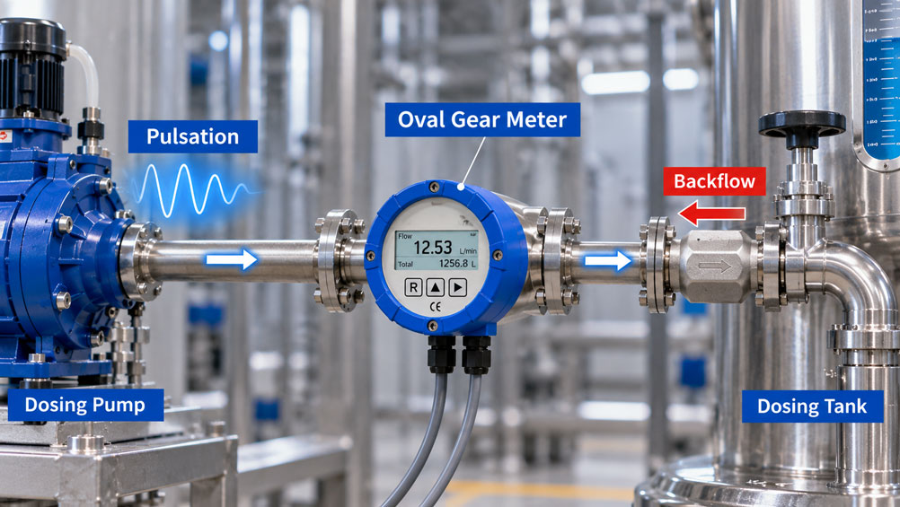
A dosing pump does not always deliver a completely uniform liquid flow. With piston, diaphragm or other cyclically operating pumps, the flow rate rises and falls within each pump stroke.
The average value may, for example, remain constant at 5 l/min while the actual instantaneous flow rate fluctuates significantly above and below this value within short periods of time.
For an oval gear meter, such pulsating flow is generally less problematic than for many flow-velocity-dependent measuring principles.
The reason lies in the measuring principle: Two oval gears divide the liquid flow into defined partial volumes. Each rotational movement therefore corresponds to a specific displaced liquid volume.
Nevertheless, this does not mean that pulsations are irrelevant to the overall measurement and dosing task.
Strong pressure fluctuations change the load on the oval gears and bearings. The instantaneous flow rate can fluctuate significantly. After a valve is shut off, elastic lines or pressure accumulators can continue to deliver liquid. During pressure equalization, the direction of flow may even reverse briefly.
This backflow is particularly important for dosing applications.
An oval gear meter can generally also rotate mechanically in reverse. Whether the connected electronics detect this reverse flow as negative volume, however, depends on the pulse transmitter and signal evaluation being used.
A single pulse channel initially transmits only individual events. A single pulse does not indicate the direction in which the oval gear has moved.
For unambiguous direction information, suitably designed measuring systems can, for example, evaluate two phase-shifted signals.
In a dosing system, three quantities must therefore be distinguished: the actual forward flow, any possible backflow and the volume total counted by the electronics.
The key point is: An oval gear meter is generally very well suited to pulsating flow. For precise dosing, however, pump pulsation, pressure fluctuations, filtering of the instantaneous value, material in flight, possible backflow and the direction detection of the electronics used must all be considered together.
Table of Contents
- How does an oval gear meter work?
- What does pulsating flow mean?
- Why oval gear meters generally handle pulsations well
- Distinguishing instantaneous flow from total volume
- Why pressure fluctuations still matter
- Why the differential pressure across the meter is decisive
- When do pulsations become too severe?
- When is a pulsation damper useful?
- How can backflow occur after dosing?
- Can an oval gear meter measure backflow?
- Why a single pulse output cannot clearly detect direction
- How does direction-sensitive pulse evaluation work?
- How reverse movement can create apparent volume
- Correctly assessing dosing accuracy
- Consider valve cutoff and material in flight
- Correctly dimension K-factor and pulse resolution
- Why the instantaneous flow display should not be filtered too strongly
- When can a check valve be useful?
- Continue to consider viscosity and gas bubbles
- Correctly design installation and pipework
- Systematically diagnose typical faults
- Suitable oval gear meters from ICS Schneider
- Conclusion
- Frequently asked questions about oval gear meters with pulsating flow
1. How does an oval gear meter work?
An oval gear meter belongs to the positive displacement flow meter category.
Its measuring chamber contains two counter-rotating oval gears.
As the gears rotate, defined partial volumes are enclosed between the oval gears and the measuring chamber housing and transported from the inlet side to the outlet side.
Each complete rotational movement therefore corresponds to a defined liquid volume.
A magnetic or other suitable pulse transmitter detects the movement of the oval gears.
The number of pulses can be used to calculate the total volume.
The instantaneous flow rate can additionally be determined from the pulse frequency.
The measuring principle therefore measures the displaced volume comparatively directly and does not require the same development of a flow profile as many velocity-based measuring principles.
2. What does pulsating flow mean?
With pulsating flow, the volumetric flow rate is not constant over time.
A diaphragm pump is a typical example.
During the delivery stroke, the flow rate increases. During the subsequent movement phase, it can decrease significantly.
Similar behavior occurs with piston pumps, dosing pumps and certain gear-pump or peristaltic-pump applications.
Depending on the pump principle, speed, number of pumping elements and system resistance, the pulsation can vary considerably.
The time-averaged flow can nevertheless remain completely constant.
A system may, for example, continuously deliver an average of 5 l/min even though the instantaneous flow briefly reaches 2 l/min and then 8 l/min within each pump cycle.
For the measurement, it must therefore be clarified whether the mean flow rate, instantaneous value or exact delivered total quantity is the quantity that is actually relevant.
3. Why oval gear meters generally handle pulsations well
An important advantage of the positive displacement principle is that a defined volume is measured mechanically.
The totalized volume is therefore less dependent on whether the liquid flows through the meter at a constant or fluctuating velocity.
Oval gear meters are therefore frequently used in start-stop processes and applications with pulsating flow.
However, this does not mean that the pulsation intensity can be unlimited.
Every acceleration and deceleration of the liquid also changes the forces acting on the oval gears.
Very fast or very strong pulsations can therefore generate mechanical loads far above those occurring during smooth continuous flow.
The manufacturer’s limits for pressure, flow and permissible differential pressure must therefore also be observed during dynamic peaks.
4. Distinguishing instantaneous flow from total volume
A pulsating pump can produce a very unstable instantaneous-flow display even though the measured total volume is correct.
The reason lies in the signal processing.
For total volume, the electronics count individual pulses over a longer period.
A higher flow rate temporarily generates more pulses, while a lower flow rate generates fewer.
For the instantaneous flow display, however, the current flow rate must be calculated from the time interval between pulses or the number of pulses within a short time window.
During pulsating operation, this value follows the pump strokes.
An unstable display therefore does not automatically mean that the volume measurement is inaccurate.
| Measured quantity | Effect of pulsation | Practical significance |
|---|---|---|
| Total volume | Often comparatively stable | Particularly relevant for batch and dosing quantities |
| Instantaneous flow | Can fluctuate strongly | Shows the actual pump dynamics |
| Filtered flow | Smoother average value | Easier to display, but slower response |
| Pulse sequence | Time intervals fluctuate | Direct information about rotor movement |
When troubleshooting, the first step should therefore always be to determine which of these quantities is actually abnormal.
5. Why pressure fluctuations still matter
Flow pulsations and pressure pulsations are often linked within a pipeline.
When a pump accelerates the liquid, the pressure increases depending on the resistance of the system.
When the liquid flow is subsequently decelerated, the pressure changes again.
Reflections and pressure surges caused by valves, hose volumes, accumulators and long pipelines can also occur.
The oval gear meter is therefore not only exposed to changing flow, but simultaneously to a dynamic pressure field.
The maximum occurring system pressure is relevant for the housing.
For the movement of the oval gears, the pressure difference between the inlet and outlet also plays a decisive role.
6. Why the differential pressure across the meter is decisive
The oval gears rotate because the pressure on the inlet side is higher than on the outlet side.
This differential pressure generates the torque required to overcome friction and flow resistance inside the meter.
As viscosity and flow rate increase, the required pressure drop typically increases as well.
With a pulsating pump, this differential pressure also changes over time.
The decisive load is therefore not only the static line pressure.
A meter can, for example, be exposed to high pressure on both sides while experiencing only a small differential pressure.
Conversely, a strong pump stroke can temporarily generate a high differential pressure across the measuring chamber.
For critical applications, it can therefore be useful to monitor the pressure upstream and downstream of the meter separately.
7. When do pulsations become too severe?
A general pulsation limit expressed as a percentage cannot be specified for every oval gear meter.
The relevant factors are frequency, amplitude, medium, viscosity, meter size and mechanical design.
Very rapid pressure changes with high peaks are particularly critical.
The oval gears are continuously accelerated and decelerated.
Under unfavorable conditions, the flow may even briefly come to a standstill or reverse direction within a single cycle.
This increases mechanical stress and noise.
In applications with pronounced hydraulic pressure surges or high-frequency pulsation, it should therefore be checked whether the specific device is approved for this type of load.
If necessary, the pulsation must already be reduced hydraulically.
8. When is a pulsation damper useful?
A pulsation damper stores part of the displaced liquid volume during a pressure peak and releases it again during a low-pressure phase.
This reduces pressure and flow fluctuations.
The oval gear meter receives a more uniform liquid flow.
This can provide several advantages:
The mechanical load on the measuring chamber decreases, the instantaneous value becomes more stable, and valves and pipework are subjected to less pressure-surge stress.
A pulsation damper is not a universal accessory that can simply be installed anywhere in the pipeline.
Volume, pre-charge pressure, installation position and material must be matched to the pump and medium.
For critical dosing systems, its position should therefore be defined together with the pump manufacturer and system designer.
9. How can backflow occur after dosing?
Backflow means that the liquid temporarily moves opposite to the normal direction of flow.
There are several possible causes.
After a dosing valve closes, for example, a previously expanded elastic hose can contract again.
A pressure accumulator can push liquid back.
A difference in height between two vessels can also cause reverse flow after the pump has been switched off.
With pulsating pumps, a brief reverse movement can also occur within a pump cycle if valves or check elements do not close completely.
For a simple flow display, this movement may hardly be noticeable.
For precise volumetric dosing, however, it can be decisive.
10. Can an oval gear meter measure backflow?
Mechanically, many oval gear meters can generally also be driven by reverse flow.
However, this does not automatically mean that the connected electronics can output a negative flow value.
This capability depends on the sensor and signal version.
A direction-sensitive system requires additional information about the direction in which the oval gears are rotating.
Suitable flow meters can, for example, use two pulse channels for this purpose.
The phase relationship between the two signals indicates the direction of movement.
With a device that has only one pulse channel, however, it must be checked carefully how the evaluation electronics handle pulses generated during reverse movement.
A general statement such as “the oval gear meter measures bidirectionally” is therefore not sufficient for a dosing control system.
11. Why a single pulse output cannot clearly detect direction
A simple Hall, reed, NPN or PNP pulse output generates an electrical pulse at specific positions of the oval gear.
The control system therefore detects:
The oval gear has moved through a defined angle.
However, a single such signal does not clearly indicate whether the movement occurred in the forward or reverse direction.
A brief reverse movement can therefore also generate pulses.
If all pulses are added only positively by the PLC, the displayed total volume may be greater than the actual net transported volume.
This behavior is particularly relevant in systems that experience pressure equalization or visible line movement after each dosing cycle.
12. How does direction-sensitive pulse evaluation work?
For direction information, two sensors can be used whose signals are phase-shifted relative to one another.
During forward movement, signal A may occur before signal B, for example.
During reverse movement, this sequence is reversed.
The control system can use this information to determine the direction of rotation.
Forward movements are counted positively and reverse movements negatively.
This allows the actual net transported volume to be calculated.
This type of quadrature evaluation is explicitly used in various positive displacement flow meters for bidirectional measurement.
For the specific ICS device or electronics option, however, it must always be checked which signal type is actually available.
13. How reverse movement can create apparent volume
A simplified example illustrates the possible effect.
Assume that a meter generates 100 pulses per liter.
By the cutoff point, 98 pulses have been counted. This corresponds to:
0.98 l.
After the cutoff signal, another 0.05 l flows forward due to material in flight.
Then, because of pressure equalization, 0.02 l flows back.
The actual net transferred volume is therefore:
0.98 l + 0.05 l – 0.02 l = 1.01 l.
If a single-channel evaluation were to count both forward and reverse pulses only positively, it could instead display, in simplified form:
0.98 l + 0.05 l + 0.02 l = 1.05 l.
The example is deliberately simplified, but it illustrates the basic problem.
For dosing processes with relevant backflow, it must therefore be clarified whether the measurement system can detect the flow direction unambiguously or whether reverse flow should be prevented by design.
14. Correctly assessing dosing accuracy
The measuring accuracy of the oval gear meter is only one component of the overall dosing accuracy.
A meter may, for example, have a specified measurement deviation of ±0.5% of reading while the finished batch deviates considerably more from the target value.
Possible additional causes include:
Pump pulsation, cutoff delay, valve closing time, material in flight, backflow, pulse-signal resolution and PLC cycle time.
For a dosing system, the question should therefore not only be:
“How accurate is the flow meter?”
The decisive question is:
“How accurately does the required net quantity actually reach the target vessel?”
This quantity should be verified during commissioning using a gravimetric method or another suitable reference measurement.
15. Consider valve cutoff and material in flight
A dosing valve does not close without a time delay.
Several milliseconds or considerably longer may pass between the electrical cutoff command and the complete end of flow.
During this time, liquid continues to be delivered.
In addition, liquid that is already located between the valve and the discharge point or is being moved by stored pressure energy continues to flow.
For this reason, precise dosing systems are often switched off before the final target quantity is reached.
The required cutoff advance is determined from actual dosing cycles.
With strongly varying pump pulsation, this material in flight may vary from batch to batch.
Coarse/fine dosing or reduced delivery rate before the endpoint can then significantly improve repeatability.
16. Correctly dimension K-factor and pulse resolution
The pulse resolution determines the smallest individual volume quantity that the control system can detect.
If a meter has a K-factor of 100 pulses/l, for example, one pulse corresponds to:
1 / 100 l = 0.01 l = 10 ml.
With a purely pulse-based cutoff, a target quantity cannot then be resolved with arbitrary precision.
With a K-factor of 1,000 pulses/l, by contrast, one pulse corresponds to only 1 ml.
Sufficiently high pulse resolution is therefore particularly important for small dosing quantities.
In addition, the PLC must be capable of reliably recording all pulses even at maximum flow.
The maximum occurring pulse frequency must not exceed the input specification of the counter module or PLC being used.
17. Why the instantaneous flow display should not be filtered too strongly
A pulsating volumetric flow produces a correspondingly pulsating instantaneous value.
Averaging can make the display considerably more stable.
This is often useful for operators and process visualization.
However, filtering that is too strong can conceal relevant process information.
A defective pump valve or increasing pulsation amplitude, for example, may hardly be visible in a heavily smoothed average value.
A filtered instantaneous value should also not be confused with the actual pulse counting used for total volume.
For precise batch quantities, direct counting of the volume pulses is often more important than a smoothed flow display.
18. When can a check valve be useful?
If backflow is neither required nor desired by the process, a suitable check valve can provide a design solution.
It prevents liquid from flowing in the reverse direction after shutdown.
This can also simplify dosing evaluation.
However, the valve itself causes a pressure loss and has an opening pressure.
At very low flow rates or with highly viscous media, this additional resistance can be relevant.
The dynamic behavior of the valve must also match the pump pulsation.
A chattering or slow-closing check valve can even intensify the pulsation.
The selection should therefore be made together with the hydraulic design of the dosing line.
19. Continue to consider viscosity and gas bubbles
Even in an article focused on pulsation, the properties of the medium remain relevant.
Viscosity influences pressure loss, internal leakage across gaps and the drive pressure required for the oval gears.
A change in temperature can therefore simultaneously change the hydraulic dynamics of the measuring line by altering viscosity.
Gas bubbles are particularly problematic.
An oval gear meter is fundamentally designed to measure liquid volume.
If a compressible gas bubble is carried along, it can alter the dynamic behavior and affect the volume measurement.
On the suction side of a pump, insufficient inlet conditions, degassing and cavitation should therefore be avoided in particular.
The meter should remain completely filled with liquid during measurement.
20. Correctly design installation and pipework
One advantage of oval gear meters is that, unlike many velocity-based flow-measurement principles, they normally do not require long straight inlet and outlet runs for flow-profile development.
However, this does not mean that the rest of the pipework is irrelevant.
The medium should be sufficiently clean upstream of the meter.
Particles can become trapped between the moving components and the measuring chamber and cause both measurement errors and mechanical damage.
Depending on the application, a suitable filter may therefore be useful.
Its pressure drop must be taken into account, particularly at high viscosity and maximum flow.
With a pulsating pump, the positions of the pulsation damper, valves and check elements as well as flexible pipe sections should also be considered.
For dosing accuracy, it is ultimately also important where the cutoff valve is installed relative to the meter and the actual dosing point.
21. Systematically diagnose typical faults
| Observation | Possible cause | Recommended check |
|---|---|---|
| Instantaneous value fluctuates strongly, total quantity is correct | Normal pump pulsation | Evaluate pulse sequence and average value separately |
| Dosed quantity is always too high | Material in flight or delayed valve closing | Record cutoff point and final quantity together |
| Displayed quantity increases despite visible backflow | Single-channel pulse evaluation does not detect direction | Check signal type and direction information |
| Dosed quantity varies from batch to batch | Variable pulsation, material in flight or backflow | Record pump pressure, pulses and valve signal simultaneously |
| Meter produces unusual noise | Strong pressure pulsation, gas content or mechanical loading | Check differential pressure and medium condition |
| Flow drops to zero during each pump stroke | Very pronounced pulsation | Investigate pump characteristics and pulsation damping |
| Additional pulses occur after pump shutdown | Material in flight, pressure equalization or backflow | Record pulse signal and pressure profile after shutdown |
| Meter wears unusually quickly | Hydraulic shocks, particles or operation outside limits | Check filter, differential pressure and pressure peaks |
22. Suitable oval gear meters from ICS Schneider
ICS Schneider Messtechnik offers oval gear and gear flow sensors for volume measurement, dosing and process monitoring. An overview can be found under Gear Flow Sensors / Oval Gear Meters.
22.1 HySense QO400
The HySense QO400 is a compact oval gear flow sensor based on the positive displacement principle.
Depending on the size, the product family covers flow ranges from 0.03 to 660 l/min.
ICS specifies a measurement accuracy of ±0.5% of reading and a viscosity range up to 3,000 mPa·s.
Depending on the version, the medium temperature can be up to 125 °C and the maximum operating pressure is specified as up to 68 bar.
The sensor is available with a PNP output and M12 x 1 connection.
For applications involving relevant backflow, however, it must be checked separately whether the specific signal and evaluation version provides direction information.
22.2 Flowal Plus Oval Gear Meter
The Flowal Plus is designed for measuring volume and volumetric flow in a wide range of industrial applications.
The measuring element consists of a measuring chamber with oval gears and can be combined with a pulse transmitter or multifunction electronics.
Different material combinations allow adaptation to various liquids.
For dynamic dosing applications, the specific combination of measuring chamber, pulse transmitter and evaluation electronics should be selected according to the required pulse resolution and direction information.
22.3 Flowal OF
The Flowal OF is a compact flange-mounted version with multifunction electronics.
ICS specifies flow ranges from 1 to 700 l/min and a measurement accuracy of ±0.5% of reading.
The series is designed for Newtonian, non-abrasive liquids such as water, oils, alkalis, acids, greases, alcohols, fuels, solvents, paints and coatings.
With the MFE-3, a temperature sensor can also be integrated to compensate for temperature-dependent volume changes and calculate mass.
22.4 Further Technical Article
The effects of viscosity, pressure loss, filtering and basic pump pulsation are discussed in greater detail in the article “Oval Gear Meters for Viscous Media: Correctly Designing for Viscosity, Pressure Loss and Pulsation”.
This article complements that topic by focusing on backflow, direction detection and the effects on the actual dosing quantity.
23. Conclusion
Oval gear meters are generally very well suited to pulsating and intermittent liquid flows.
The positive displacement principle measures defined partial volumes and therefore enables precise totalization even when the flow velocity changes.
An unstable instantaneous-flow display does not therefore automatically mean an inaccurate total quantity.
Nevertheless, very strong or high-frequency pulsations must not be ignored.
They generate changing differential pressures and continuously accelerate and decelerate the oval gears. Hydraulic pressure surges can additionally increase the mechanical load.
If necessary, suitable pulsation damping can stabilize the measuring line.
Backflow is particularly important in dosing processes.
After shutdown, elastic lines, accumulators, differences in height or pump dynamics can cause temporary reverse flow.
Whether this reverse flow is correctly subtracted from the measured volume depends on the signal technology.
A single pulse channel fundamentally does not provide unambiguous information about the direction of rotation. True direction-dependent volume counting therefore requires appropriately designed sensor and evaluation electronics.
The accuracy of a dosing process is also not determined solely by the meter’s specified accuracy.
Pulse resolution, valve closing time, PLC processing, material in flight, pressure equalization and backflow are also part of the error budget.
For reliable design, the following sequence therefore applies:
Determine pump characteristics → check pulsation amplitude and pressure peaks → select the oval gear meter to suit flow and viscosity → evaluate K-factor and pulse frequency → investigate possible backflow → define the required direction detection → determine valve material in flight → if necessary, design a pulsation damper or check valve → verify actual dosing cycles using a reference quantity → optimize the cutoff point based on the actual net quantity.
The most important practical principle is therefore: With pulsating flow, it is not decisive whether the instantaneous-flow display appears completely stable. What matters is whether every actual volume transfer – including possible backflow – is correctly evaluated by the measurement and dosing logic.
24. Frequently asked questions about oval gear meters with pulsating flow
24.1 Are oval gear meters suitable for pulsating flow?
Yes. The positive displacement principle is generally very well suited to fluctuating, pulsating and intermittent liquid flows.
24.2 Why does the displayed instantaneous flow still fluctuate?
Because the actual flow rate of the pulsating pump fluctuates. The oval gear meter reproduces this change through the time-varying pulse frequency.
24.3 Can the total quantity still be correct?
Yes. With clearly forward-directed flow, the accumulated pulse count can provide a very stable volume measurement even though the instantaneous value fluctuates strongly.
24.4 Can excessive pulsation damage an oval gear meter?
Yes. Very strong or high-frequency pulsations and hydraulic pressure surges can increase the mechanical load. The permissible operating conditions of the specific meter must be observed.
24.5 What does a pulsation damper do?
It reduces pressure and flow fluctuations and can therefore reduce both mechanical stress and fluctuations of the instantaneous value.
24.6 Is static system pressure or differential pressure more important?
Both are relevant. The system pressure must remain below the permissible housing pressure. The differential pressure across the measuring chamber, however, largely determines the driving torque and hydraulic loading of the oval gears.
24.7 Can an oval gear meter run backwards?
Many positive displacement meters can mechanically rotate under reverse flow. Whether this produces a correctly negative measured signal depends on the specific sensor and electronics version.
24.8 Can a single PNP pulse output detect flow direction?
A single pulse channel does not initially provide unambiguous information about the direction of rotation. Reliable direction detection requires a signal evaluation system designed for that purpose.
24.9 How can flow direction be detected electronically?
One possibility is the use of two phase-shifted pulse signals. The sequence of these signals allows the evaluation electronics to determine the direction of rotation.
24.10 What happens if backflow is not detected?
With simple positive pulse counting, pulses generated by reverse movement may also be added to the total volume. The displayed quantity can then differ from the actual net transferred quantity.
24.11 Why does backflow occur after shutdown?
Possible causes include pressure equalization, elastic hoses, accumulators, differences in height, pump movement or valves that do not close completely.
24.12 Can a check valve solve the problem?
It can prevent unwanted reverse flow. However, opening pressure, pressure loss, viscosity and dynamic behavior must be suitable for the application.
24.13 What determines dosing accuracy?
In addition to the measuring accuracy of the meter, particularly pulse resolution, valve closing time, material in flight, pump dynamics, PLC cycle time and possible backflow.
24.14 What does the K-factor mean?
The K-factor describes the number of pulses generated per unit of volume, for example pulses per liter.
24.15 Why is high pulse resolution important for small dosing quantities?
The smaller the volume represented by one pulse, the more precisely a pulse-based dosing control system can resolve the required quantity.
24.16 Should the instantaneous flow be heavily filtered?
Moderate averaging can be useful for display purposes. However, excessive filtering can conceal actual pump dynamics and fault patterns.
24.17 Does an oval gear meter require straight inlet runs?
Unlike many velocity-based flow-measurement principles, long straight inlet sections are normally not required for flow-profile development.
24.18 Must oval gear meters be protected against particles?
Yes. Particles can become trapped between the moving components and the measuring chamber. Suitable filtration may therefore be advisable depending on the application.
24.19 Is the HySense QO400 suitable for pulsating applications?
The QO400 operates according to the positive displacement principle and is therefore generally of interest for dynamic volume measurements. However, the specific pulsation load, pressure peaks and required direction detection must be checked for the individual application.
24.20 What data does ICS Schneider require for selection?
Useful information includes minimum, average and maximum flow, pulsation frequency or pump type, normal and maximum pressure, possible pressure peaks, medium, viscosity at minimum and maximum temperature, required dosing quantity, required dosing accuracy, possible backflow, desired output signal, PLC input and information about the valve, filter and any existing pulsation damping.