


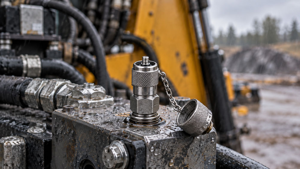
A MINIMESS test point may remain installed for years on a hydraulic power unit, construction machine or outdoor test line. It is used only occasionally, yet must provide clean, safe access for pressure measurement whenever servicing is required. In the meantime, rain, condensation, road salt, dust and temperature fluctuations affect the test coupling. The long periods without operation make these conditions particularly deceptive: moisture and dirt can accumulate beneath the protective cap even though the rest of the hydraulic system appears to function normally.
The problem is not limited to external rust. A contaminated coupling head can damage the sealing and valve area during connection or introduce particles into the measurement path. Corrosion at the screw-in connection can compromise long-term leak tightness, while an aged microbore hose can make the next measurement mechanically unsafe. A plausible measured value alone says nothing about the condition of the connection.
This technical article explains how to select, install, protect against moisture and inspect MINIMESS test points in outdoor systems. It focuses on the interaction between the material, protective cap, check valve, seals and test hose, as well as the limitations of connecting under pressure. Pressure and temperature specifications never apply universally to the entire MINIMESS product family, but only to the particular configuration for which they have been verified.
Table of Contents
- What a MINIMESS Test Point Must Withstand Outdoors
- Understanding the Coupling Principle and Pressure Sealing
- Distinguishing the Three Main Damage Mechanisms
- Corrosion Caused by Water, Salt and Damaged Surfaces
- Coated Steel or Stainless Steel: Making the Right Choice
- What the Dust Cap Actually Does
- Controlling Condensation and Moisture Beneath the Cap
- Designing the Installation Location for Weather Exposure and Servicing
- Correctly Matching the Coupling Series and Mating Connection
- Checking the Screw-In Thread and Process Seal
- Matching Seal Material to the Medium and Temperature
- Assessing Operating Pressure and Pressure Peaks Across the Complete Assembly
- Accounting for Frost, Heat Exposure and Temperature Changes
- Correctly Specifying Microbore Hoses for Outdoor Use
- Distinguishing Hose Behaviour from the Reliability of the Measured Value
- Checking the Test Point Before Every Connection
- Connecting Under Pressure and Disconnecting Safely
- Diagnosing Typical Damage and Measurement Problems
- Organising Inspection, Replacement and Documentation
- Improving New and Existing Outdoor Test Points
- Suitable MINIMESS Products from ICS Schneider
- Conclusion: Managing Cleanliness, Materials and Pressure Limits Together
- Frequently Asked Questions About MINIMESS Test Points Outdoors
1. What a MINIMESS Test Point Must Withstand Outdoors
A permanently installed test point must remain closed during normal plant operation and provide defined access to the fluid circuit when needed. Outdoors, it must also remain mechanically operable, clean and leak-tight after long periods without use. A coupling may be suitable in terms of pressure rating when new, yet still have the wrong material or cap configuration for an unprotected location exposed to salt.
The requirements therefore depend on more than the maximum hydraulic pressure. Rainfall, possible exposure to salt or chemicals, ambient temperature, connection frequency and accessibility for cleaning are also decisive. A test point on a dry hydraulic block beneath an engine cover must be assessed differently from one mounted externally on a chassis in an area exposed to spray water.
Two operating conditions should therefore be considered separately during specification: most of the time, when the protective cap is fitted, and the short measurement phase with a hose connected. The permanently installed test point is not the same component as the temporarily connected measurement line. Each has its own material and pressure limits.
2. Understanding the Coupling Principle and Pressure Sealing
A conventional MINIMESS test point is a mechanically released check valve. Without the appropriate mating coupling, its internal valve and sealing arrangement closes off access to the process. When a compatible connecting fitting is screwed on as intended, the valve opens mechanically, establishing the measurement path to the hose or instrument. The designated sealing points provide leak tightness.
The protective cap must be distinguished from this function. It protects the outside of the coupling from contamination and damage. Certain versions may provide supplementary securing or sealing functions. However, it does not replace the properly functioning internal shutoff of the test point. If process medium repeatedly appears at the valve opening after disconnection, the cap must not be regarded as a repair for the defect.
During connection, the coupling thread, opening travel, seal geometry and mating fitting must all match. A connection that can be screwed on for a few turns is not necessarily compatible. A connection made stiff by corrosion, in particular, must not be forced to fit by applying extra torque.
3. Distinguishing the Three Main Damage Mechanisms
External corrosion initially attacks exposed surfaces, threads, wrench flats and cap attachments. As damage progresses, operation can become more difficult; damaged sealing surfaces or connection areas may eventually impair function. Visible discolouration, however, does not automatically mean that internal pressure is being lost. The location and extent of the corrosion are decisive.
Contamination and moisture in the coupling area primarily threaten the next connection operation. Fine sand, swarf and dried deposits can become trapped between sealing partners. Damp particles also adhere more readily to tight contours. When the mating coupling is attached, this can cause leakage or damage to the sealing area.
Damage to the hose and mating fitting often becomes apparent only during testing. Abrasion, kinks, corrosion on end fittings and aged hose materials are separate risks. An intact test point does not justify using a hose assembly of unknown condition or one that is visibly damaged. The three damage mechanisms are therefore recorded separately during inspection.
4. Corrosion Caused by Water, Salt and Damaged Surfaces
Water alone does not cause the same degree of exposure under all conditions. Long periods of wetness, salt deposits and repeated wet-dry cycles are particularly critical. Spray mist, road salt, seawater and cleaning chemicals alter the electrochemical conditions at the surface. Moisture can remain for extended periods in threads, beneath a cap with poor drainage or at contact points between different components.
Coated surfaces require particular attention around tool engagement points and edges. Damage occurs there through repeated use of wrenches, rubbing against brackets or mechanical impacts. If corrosion starts at such a point, simply removing visible rust is not sufficient. It is necessary to determine whether the thread, sealing area and load-bearing cross-section still meet the permissible condition.
The corrosion resistance of a coating documented in a salt-spray test describes a laboratory test under specified conditions. It does not guarantee service life under real outdoor conditions. A test point subjected to road salt, mud, frost and movement may experience stresses different from those in a test chamber. A corrosion test rating therefore cannot replace suitable installation design or regular condition inspections.
5. Coated Steel or Stainless Steel: Making the Right Choice
Hydrotechnik describes zinc-nickel coating as corrosion protection for MINIMESS components made of free-cutting steel. This is a suitable starting point for many conventional hydraulic applications. In outdoor locations with persistent salt exposure or aggressive cleaning agents, however, it should be checked whether the conditions require a stainless steel version or a special offshore configuration.
Manufacturer documentation for the MINIMESS 1620 series includes versions made from stainless steel 1.4571, among others. Stainless steel is not immune to corrosion regardless of environmental conditions. In particular, chloride-containing water and sheltered crevices can be problematic even for suitable stainless steels. The specific material, contacting components, surface finish and complete configuration, including the cap and retaining elements, are decisive.
A single stainless steel test point may provide only a partial solution if the screw-in block, adapter or adjacent bracket is made of a different material. Galvanic corrosion can play a role where dissimilar metals are in electrically conductive contact and moisture is also present. Material selection must therefore consider the entire installed assembly. Hydrotechnik offers separate, appropriately designed special solutions for direct seawater exposure.
6. What the Dust Cap Actually Does
A correctly specified protective cap largely protects the sensitive coupling area from dust, splashed dirt and accidental mechanical contact while it is not in use. Depending on the product, MINIMESS test points are available with metal or plastic caps. After measuring, the cap is correctly refitted; its thread compatibility and any provision for preventing it from coming loose form part of the selection process.
For versions with a metal cap, an O-ring may, for example, serve as an anti-vibration retainer. Without a corresponding manufacturer specification, this must not be taken as proof of a defined water- or pressure-tight seal for the complete cap connection. Nor is a protective cap automatically an electrically rated IP protective enclosure. Actual protection against moisture depends on geometry, seals, condition and installation orientation.
A missing, damaged or incorrectly fitted cap is therefore a maintenance finding. An unsuitable replacement cap may damage the thread or fail to protect the coupling head adequately despite appearing to cover it. Where vibration or frequent removal is involved, the retaining chain or other intended cap fastening should also be checked. The protective cap must not impose any additional load on the test point.
7. Controlling Condensation and Moisture Beneath the Cap
Moisture at a test point does not come only from direct rainfall. After cold nights, dew and condensation can form as the surrounding air becomes warmer and more humid. Cleaning operations or dirt carried into the area can also introduce water around the coupling head. Covering a connection while it is still wet can allow moisture to remain in small crevices for longer.
Before connecting, check whether the area beneath the protective cap is dry and clean. Visible water and loose deposits are removed using a method compatible with the materials and medium, without pushing dirt into the valve. Sealing surfaces must not be scraped with hard tools. Cleaning and preservation products may only be used if they have been approved for the specific test point and existing elastomers or their compatibility has otherwise been demonstrated.
The solution is not to completely enclose every coupling in an arbitrary additional cover. A cover without adequate drainage can actually retain moisture. A protected installation location, a suitable cover and a design that does not direct water onto the coupling head are more effective. If the test point regularly remains wet, the cause at the installation location should be eliminated rather than simply increasing the cleaning effort.
8. Designing the Installation Location for Weather Exposure and Servicing
A good installation location is, wherever possible, outside direct jets of spray water and dirt, remains accessible for cleaning and measurement connections, and prevents accidental contact with moving machine components. There must be sufficient clearance to unscrew the protective cap completely. A connected mating coupling must also not be pressed against housings, pipes or sharp edges.
Where feasible, a suitable bracket or enclosure can protect the test point from direct precipitation. Drainage, ventilation and the ability to carry out a safe visual inspection must be considered at the same time. A recessed connection that collects water and dirt may be less suitable than a somewhat more exposed connection with good drainage, even if it uses a high-grade material.
Retrofitted protective measures must not impair the pressure-bearing installation. Protective plates, for example, must not serve as supports for the temporary measurement hose. If a test point is relocated to a more accessible position, the pressure rating, adapters, pipework supports and, where applicable, any change to the dynamic measurement response must be reassessed.
9. Correctly Matching the Coupling Series and Mating Connection
Several coupling series are marketed under the MINIMESS name. The test hose connection must match exactly the series installed on the hydraulic block. This is especially important on older machines because the process thread at the screw-in end can easily be confused with the coupling thread. For example, an M12 × 1.5 screw-in thread on a test point does not establish that its coupling side belongs to the 1215 series.
| Series | Coupling Side | Nominal Size | Maximum Operating Pressure of the Series | Important Selection Note |
|---|---|---|---|---|
| 1620 | M16 × 2 | DN2 | up to 630 bar | Select a mating coupling specifically for 1620 |
| 1615 | M16 × 1.5 | DN2 | up to 630 bar | Do not confuse it with M16 × 2 |
| 1215 | small series-specific coupling thread | DN2 | up to 630 bar | Identify the coupling and screw-in sides separately |
| 1604 | larger series-specific coupling system | DN4 | up to 400 bar | A larger nominal size does not mean a higher pressure rating |
These values represent the highest possible series ratings, not approval for every order variant. Screw-in thread, sealing method, material, seal and temperature may reduce the permissible pressure. The supplementary ICS technical article Selecting the Correct MINIMESS Series: Identifying 1215, 1615, 1620 or 1604 provides guidance on identification.
10. Checking the Screw-In Thread and Process Seal
The process-side seal is independent of the external hose coupling. Depending on the item, MINIMESS test points may be installed with a sealing edge, profiled sealing ring, O-ring or an approved thread sealing method. A parallel thread does not automatically seal along its thread flanks. The correct tapped hole and associated sealing geometry must be observed for the specific version.
Particularly when retrofitting an existing hydraulic block, the thread depth, counterbore, sealing surface and screw-in length must be correct. The installation torque also depends on the connection design and installation conditions. Blindly retightening a corroded test point can damage sealing surfaces or overload the block. The manufacturer’s specifications for the selected connection type are decisive.
If moisture or oil is visible at the screw-in thread, first distinguish between process leakage and liquid introduced from outside. Removing or replacing the pressure-bearing connection must only take place after the affected system has been safely isolated, secured and completely depressurised. The ability to connect under pressure does not extend to loosening the process-side screw connection.
11. Matching Seal Material to the Medium and Temperature
For the MINIMESS 1620 series, the manufacturer specifies NBR and FKM seals, among others, as well as additional seal variants in corresponding configurations. The seal must be compatible with both the process medium and its operating temperature. A seal suitable for mineral-oil hydraulics must not automatically be considered approved for every fire-resistant, biodegradable or water-based fluid.
For example, the referenced 1620 series data sheet specifies -25 … +100 °C for NBR and -20 … +200 °C for FKM. Where a plastic cap is fitted, the permissible upper temperature may be limited to +100 °C regardless of the FKM configuration. These figures apply only to the relevant variants and do not establish the limits of the connected hose or measuring instrument.
Outdoor use also requires consideration of low ambient temperatures combined with a warmer process medium. A cold connection that has not been used for a long time may display different elastomer behaviour during service than after warming up. Cleaning chemicals may also attack the external area even though they are not part of the process medium. Only suitable, approved seals and spare parts must be used for replacement.
12. Assessing Operating Pressure and Pressure Peaks Across the Complete Assembly
The maximum permissible pressure of the measurement arrangement is limited by its weakest relevant component. These include the test point, mating coupling, hose assembly, adapters and measuring instrument. A test point rated for pressures of up to 630 bar does not turn a connected hose assembly with a lower rating into a 630-bar system.
Furthermore, the manufacturer distinguishes between the maximum pressure for measurement tasks and a lower permissible pressure for dynamic applications involving MINIMESS microbore hoses. This distinction is crucial at a pulsating measurement point. Specification must consider not only the steady system pressure, but also pressure peaks, pulsations, temperature and the intended duration of operation of the temporary connection.
The burst pressure of a component is not a permissible operating pressure rating. Nor can suitability be inferred from the pressure scale on the connected pressure gauge. If the planned measurement exceeds the load limits, a suitable measurement setup or different pressure rating must be selected. An existing coupling must not be assumed suitable for the pressure simply because it shows good external corrosion resistance.
13. Accounting for Frost, Heat Exposure and Temperature Changes
Outdoor systems can experience winter temperatures well below the temperature range of a conventional hose assembly. For the standard MINIMESS DN2 and DN4 microbore hoses described, the manufacturer’s data sheet gives an operating temperature range of -20 … +100 °C. A suitable low-temperature version must be selected separately if lower temperatures occur. The limits of the test point itself may differ.
In freezing conditions, the risk of external water freezing in movement-related gaps must be considered alongside material and seal resistance. Ice or frozen dirt can block a protective cap. Such a connection must not be opened by forceful twisting or blows. Reduced flexibility of the hose at low temperatures must also be taken into account during servicing.
In summer, dark housings, nearby engine and exhaust components or intense sunlight can produce high surface temperatures. Both process and ambient temperatures, and the weakest component in each case, must therefore be checked. Temperature changes also promote cycles of condensation and drying, making regular inspection of the protective cap and coupling area for trapped moisture necessary.
14. Correctly Specifying Microbore Hoses for Outdoor Use
A MINIMESS microbore hose connects a difficult-to-access measurement point to a pressure gauge, pressure sensor or portable measuring instrument. Its small nominal bore limits the required fluid volume and makes routing through confined machine areas easier. At the same time, bending radius, pressure loading, end fittings and the condition of the outer cover must be considered. Hose length should suit the measurement task and provide sufficient allowance for routing without strain.
The Hydrotechnik data sheet explicitly distinguishes between measurement tasks and dynamic applications for the following standard versions. The operating pressure values listed apply only under the specified conditions and do not replace approval of the complete assembled hose.
| Hose Version | Maximum Pressure for Measurement Tasks | Maximum Pressure for Dynamic Applications | Minimum Bend Radius |
|---|---|---|---|
| DN2-400 | 400 bar | 300 bar | 20 mm |
| DN2-630 | 630 bar | 500 bar | 20 mm |
| DN4-315 | 315 bar | 240 bar | 40 mm |
| DN4-450 | 450 bar | 340 bar | 40 mm |
A practical comparison illustrates the significance: at a continuously pulsating measurement point operating at 350 bar, the DN2-400 hose’s dynamic rating of 300 bar is insufficient, even though its rating for measurement tasks is 400 bar. According to the data sheet, the DN2-630 version offers a higher dynamic pressure rating; nevertheless, it would only be suitable if the mating fittings, test point, measuring instrument, temperature and all other aspects of the load case were also verified as suitable.
Hoses must not be subjected to tensile loads, twisting or compression during operation. Areas of chafing, crushing and tight bends near the end fittings must be avoided. Protective springs and abrasion protection can be useful if they suit the hose and do not compromise the required minimum bend radius. Hydrotechnik prohibits painting over the hose assemblies described; a subsequently applied paint or corrosion-protection coating is therefore not an appropriate standard measure.
15. Distinguishing Hose Behaviour from the Reliability of the Measured Value
In static pressure measurement, a sufficiently leak-tight hose completely filled with a suitable fluid can transmit a reliable measured value after pressure equalisation. Additional conditions apply to fast pressure peaks and pulsating profiles. Hose volume, length, nominal bore, elasticity and trapped gas bubbles can affect transmission over time. The pressure peak displayed by the connected sensor is therefore not necessarily identical to its profile directly at the process connection.
A long, narrow hose can alter the transmission of dynamic components; an air pocket can increase this effect further. This cannot be corrected universally simply by shortening the hose, since sensor bandwidth, medium and the specific geometry of the entire measuring line also play a role. For transient measurements, the transmission path must be assessed as part of the measurement system.
Outdoors, temperature fluctuations can also alter fluid viscosity and hose behaviour. If a measured value rises only slowly after connection or responds with a delay, first check leak tightness, valve opening, trapped air and hose routing. A faulty or contaminated mating coupling can restrict flow through the connection even though the measuring instrument itself is operating correctly.
The assessment of time-dependent pressure peaks is complemented by safety considerations for hose use in the ICS article Using MINIMESS Test Hoses Safely: Pressure Rating, Ageing and Hose Whip.
16. Checking the Test Point Before Every Connection
A recurring service inspection begins by identifying the measurement point and obtaining approval for the intended test procedure. The required measuring range, possible pressure loading, medium and matching mating coupling must be established before removing the protective cap. Inspect the process connection externally for traces of oil, rust, damage or impermissible movement.
- Identify the measurement point: Check its designation, MINIMESS series, pressure range and intended measurement against the plant documentation.
- Assess the protective cap: Visually inspect for damage, corrosion and secure attachment. Only release the cap using the specified procedure.
- Inspect the coupling area: Identify and assess water, dust, swarf, damage to sealing surfaces and unusual traces of process medium before connection.
- Clean appropriately: Use only compatible cleaning aids, do not push dirt into the valve opening and do not damage any sealing surfaces.
- Inspect the measurement line: Consider pressure rating, temperature range, fittings, age, chafing, bend radius and any residual pressure.
- Only then connect: Attach the approved mating coupling without cross-threading, in accordance with the manufacturer’s instructions, and check the measurement setup for leak tightness and correct indication.
A test point with uncertain sealing integrity, a cap seized by corrosion or clearly damaged coupling geometry must not be made operable through an improvised attempt at connection. It must be professionally assessed and, where necessary, taken out of service. This is particularly important if a hose could only be connected by applying unusual force.
17. Connecting Under Pressure and Disconnecting Safely
MINIMESS test points in suitable configurations allow a matching mating coupling to be connected as intended while the system is pressurised. This capability is a key feature of the system, but it does not constitute general permission to open arbitrary couplings or hoses under pressure. It applies only within the permissible pressure, temperature and media ranges and in accordance with the manufacturer’s operating and safety instructions.
Connection and disconnection procedures must take account of the plant, the complete measurement path and any pressure trapped in the hose. The associated work instruction must specify whether and under what conditions the combination used may be disconnected and how residual pressure is to be handled safely. A process-side screw connection must never be confused with a hose coupling: loosening it requires the affected system to be safely depressurised.
Escaping hydraulic fluid at high pressure can penetrate the skin even if the external injury appears minor. A leak must therefore never be located using fingers or hands. If high-pressure fluid injection is suspected, immediate emergency medical attention is required, explicitly identifying the incident as a pressurised-fluid injection injury. Hot media, uncontrolled hose movements and ejected components must also be considered in the risk assessment.
Liquid applications must also be explicitly distinguished from gas or accumulator charging tasks. The suitability of a conventional hydraulic test point for the relevant fluid group is not automatic approval for arbitrary compressed gases, oxygen or hydrogen. Components and procedures specifically approved for these applications are required.
18. Diagnosing Typical Damage and Measurement Problems
At outdoor measurement points that have been installed for a long time, different symptoms call for different measures. The decisive question is whether the external protective function, pressure seal, mechanical coupling or measurement path is affected. A visual inspection may reveal a defect, but cannot on its own verify that pressure resistance has been maintained.
| Observation | Possible Cause | Appropriate Action |
|---|---|---|
| Moisture and early rust formation beneath the cap | Condensation, poor drainage, damaged surface protection | Dry and assess the test point after safe authorisation; improve the installation location and cap configuration |
| Protective cap can only be removed with considerable force | Corrosion, damaged thread, deposits or icing | Do not use force; have the cause and need for replacement assessed professionally |
| Dirt or swarf on the exposed coupling head | Missing cap, poor servicing practices or ingress of dirt from the surroundings | Clean appropriately and inspect sealing surfaces before connection |
| Recurring traces of oil at the valve opening after disconnection | Contaminated or damaged check valve or sealing element | Do not conceal the problem by merely tightening the cap; inspect or replace the test point after depressurisation |
| Oil film around the screw-in connection | Damaged process seal, loose connection or oil introduced externally | Identify the source; only work on the pressure-bearing connection after depressurisation |
| Mating coupling cannot be screwed on correctly | Wrong MINIMESS series, damaged thread or foreign matter | Identify the coupling series and geometry; do not force the connection |
| Pressure signal responds slowly or is unusually damped | Trapped air, restricted valve opening, hose or measurement system dynamics | Check the measurement setup and flow passage; assess suitability for dynamic measurement separately |
| Chafing or kinking of the test hose | Unsuitable routing, excessive bending or external movement | Do not continue using the hose if safety-relevant damage is present; select an appropriate replacement hose |
Traces of oil on the cap alone do not prove either a defective primary seal or a damaged process connection. Residual quantities may also remain after previous servicing. The cause must be systematically located under safe conditions. Seemingly successful retightening, additional sealant or an external coat of paint is no substitute for this diagnosis.
19. Organising Inspection, Replacement and Documentation
A permanently accessible outdoor test point should be included in the maintenance schedule as a component in its own right. Useful inspection criteria include the presence and condition of the cap, cleanliness of the coupling thread, the coating, noticeable corrosion, external signs of leakage and access for safe connection of measurement equipment. Additional inspection may be appropriate after periods of road-salt exposure, high-pressure cleaning, flooding or mechanical damage.
For the MINIMESS hoses described in the Hydrotechnik data sheet, the manufacturer recommends inspection every 12 months in normal applications; for more demanding conditions, such as multiple-shift operation, it specifies 6 months. Hydrotechnik also recommends replacing these hose assemblies no later than every 5 years. These are the manufacturer’s recommendations for the hoses concerned, not universally applicable inspection intervals for every permanently installed test point or other hose type.
Under more severe outdoor conditions, shorter risk-based intervals are required if the condition and use indicate a need. Regardless of age, damaged hoses and couplings that are no longer safe to operate must be replaced. Calibration of the connected pressure gauge can neither replace nor remedy mechanical damage to the hose or test point.
A practical maintenance record includes the measurement point tag, installation location, coupling series, material, seal, cap type, hose identification and documented pressure limits. It also records the inspection date, environmental findings, visible damage, work carried out and the next scheduled inspection. For a replacement part, it must remain possible to identify the exact version originally installed.
20. Improving New and Existing Outdoor Test Points
When planning a new installation, first establish the pressure and medium, maximum and minimum temperatures, and outdoor exposure. Then select the coupling series, process-side seal, material and protective cap. Only after these conditions are defined should the matching mating coupling, microbore hose and measuring instrument be assembled into a suitable measurement solution.
Retrofitting is not always necessary in existing installations. Often, a suitable, intact protective cap combined with improved drainage and controlled cleaning will improve the situation. If corrosion repeatedly occurs on components made from coated steel, a suitable stainless steel variant or a special version designed for salt-laden outdoor environments may be appropriate. Changing the material alone, however, does not eliminate poor water drainage or an unsuitable seal selection.
Especially on older systems, the exact interface must be identified before replacement. The coupling thread and the thread at the screw-in end serve different purposes. A seemingly similar replacement coupling with different valve travel or sealing seat is not automatically interchangeable. For retrofits, the drawing, existing mating component and, where possible, part number should be documented.
The investment is not justified solely by the maximum pressure specification. A measurement point that is easy to clean, remains accessible over the long term and is unambiguously identified during servicing reduces troubleshooting time and downtime. A weather-protected, correctly specified connection therefore provides more benefit than an oversized individual component installed in an unsuitable location.
21. Suitable MINIMESS Products from ICS Schneider
21.1 Original MINIMESS 1620: A Widely Used Measurement and Service Connection
The MINIMESS 1620 series has an M16 × 2 coupling connection and is suitable for numerous hydraulic measurement and diagnostic tasks. Different screw-in connections, seals and versions made from coated steel and stainless steel are available. For outdoor installation, the appropriate cap design, environmental corrosion exposure and permissible values of the specific order variant must be assessed in particular.
21.2 MINIMESS 1615: Safely Maintaining Existing M16 × 1.5 Connections
The MINIMESS 1615 series is especially relevant where this coupling geometry is already used in the installation. It must not be combined with a 1620 mating coupling solely because its outside diameter is similar. When procuring replacements for outdoor use, material, protective cap, seal and operating pressure matter as well as the correct interface.
21.3 MINIMESS Hoses: Measurement Lines with Defined Pressure and Bending Loads
MINIMESS hoses are available as custom-assembled microbore lines with different nominal sizes, pressure ratings and end fittings. For outdoor servicing, safe routing, suitable temperature limits, protection against abrasion and the distinction between measurement and dynamic pressure loading are essential. Hose, test point and measuring instrument are selected as one complete measurement chain.
21.4 Original MINIMESS from Hydrotechnik: Checking Special Versions for Specific Applications
Alongside standard test points, MINIMESS from Hydrotechnik documents special series and accessories. These include solutions for increased corrosion exposure and particular environmental conditions. Where there is prolonged contact with salt-laden spray water or particularly low temperatures, selecting a version expressly intended for these conditions is preferable to applying the characteristics of a standard item across the board.
The MINIMESS Couplings and Hoses category provides the complete overview. Current manufacturer documentation and the specifications of the full connection assembly are decisive for the final selection.
22. Conclusion: Managing Cleanliness, Materials and Pressure Limits Together
A MINIMESS test point outdoors needs more than a high nominal pressure rating. The decisive factors are a material suitable for the corrosion exposure, an undamaged and correctly used protective cap, permanently compatible seals, and an accessible installation location with proper drainage. The condition of the coupling must be visually assessed during every service visit before the matching mating fitting is connected.
The connected microbore line has its own operating and temperature limits. Under pressure pulsations in particular, these can be lower than the ratings for measurement tasks alone. A valid measured value confirms the operation of the measuring instrument under the test conditions, but not automatically the sound condition of all pressure-bearing components.
Determine outdoor exposure → Identify the MINIMESS series and process connection → Select material, seal and protective cap → Check the overall pressure limit and hose routing → Clean and inspect the test point before connection → Document its maintenance condition
The most important practical principle is therefore: A permanently reliable outdoor test point results not from the protective cap alone, but from the coordinated selection and maintenance of the coupling, seal, installation location and complete measurement line.
23. Frequently Asked Questions About MINIMESS Test Points Outdoors
23.1 Are MINIMESS Test Points Generally Suitable for Outdoor Use?
Depending on the material, surface protection, seal and protective cap, suitable versions can be selected for outdoor installations. General approval cannot be inferred from the MINIMESS designation alone. Site exposure, medium, pressure and temperature must suit the specific item.
23.2 What Is the Purpose of the Dust Cap on a MINIMESS Test Point?
It protects the unused coupling head against dust, dirt, moisture and mechanical effects. Internal pressure shutoff is provided by the test point’s designated valve and sealing arrangement. Any additional sealing or retaining function of the cap depends on the specific version.
23.3 Is a Metal Cap Automatically Better Than a Plastic Cap?
No. Both versions have product-specific limits. A metal cap can be mechanically robust, while a plastic cap may impose different requirements in terms of temperature and resistance. What matters is a cap version approved for the application, secure attachment and moisture protection of the overall installation.
23.4 Is a Dust Cap Watertight or Rated IP67?
This must not be assumed in general. Simply being described as a dust cap does not establish an IP protection rating. If a defined level of water protection is required, the manufacturer’s specifications must confirm it for the particular version.
23.5 What Should Be Done If Water Collects Beneath the Protective Cap?
Water and dirt must not be introduced into the coupling or valve area during a measurement. The connection must be cleaned using the specified safe procedure and inspected for damage. Recurring water accumulation also indicates that the cap, installation orientation or drainage should be improved.
23.6 Can Condensation Cause a MINIMESS Test Point to Corrode?
Yes. Repeated condensation can leave moisture in threads or narrow crevices. Prolonged wetness is particularly problematic where salt or dirt deposits are present. Suitable surface protection and an installation design that does not permanently trap water are therefore important.
23.7 Which Material Is Suitable Where Road Salt or Seawater Spray Is Present?
Material selection must be matched to the actual chloride and moisture exposure. A suitable stainless steel or dedicated offshore version may be appropriate. However, stainless steel 1.4571 is not immune to localised corrosion under all conditions; installation geometry and contacting materials remain relevant.
23.8 Can a Rusted Protective Cap Be Unscrewed by Force?
This is not recommended. It can damage threads or sealing surfaces, or apply force in an unsafe manner. A seized cap must be dealt with as part of a professional assessment; damaged parts must be safely replaced where necessary.
23.9 Can a Leaking Test Point Be Sealed by Tightening the Cap Further?
The protective cap is not a general repair solution for a leaking check valve. Repeated leakage of process medium must be investigated after the equipment has been made safe. A damaged or contaminated valve or sealing area may require replacement of the test point.
23.10 Are MINIMESS 1615 and 1620 Interchangeable?
No, not without expressly verified compatibility. The 1615 coupling side uses M16 × 1.5, while the 1620 coupling side uses M16 × 2. The opening mechanism and sealing geometry must also match. A mating coupling must not be forced on by increasing the tightening torque.
23.11 Is Every MINIMESS Test Point Approved for 630 bar?
No. For certain series and configurations, 630 bar is a possible upper limit. Other versions may have lower limits; for example, the 1604 series is listed up to 400 bar. The approval for the specific order number, including screw-in connection and seal, is what matters in actual operation.
23.12 Can I Use a 400-bar Hose on a 630-bar Test Point?
Only if all parts of the measurement chain are suitable for the actual loading. The permissible system limit is determined by the weakest component. Under dynamic loads, the permissible pressure of the specific 400-bar test hose may be lower still.
23.13 Why Does Hydrotechnik Specify Different Pressure Ratings for Hoses?
The data sheet distinguishes the maximum pressure loading for measurement tasks from that for dynamic applications. Pressure cycling and pulsation load a hose assembly differently from a suitable diagnostic application. The type of loading must therefore be known during selection.
23.14 Which MINIMESS Hoses Are Suitable for Subzero Temperatures?
According to the referenced data sheet, the standard microbore hoses listed in this article are specified for -20 … +100 °C. For lower temperatures, versions expressly designed for those conditions must be checked. The entire connection, including fittings and seals, must be suitable for the temperature range.
23.15 Can a Wet or Contaminated Test Point Cause Incorrect Measurements?
Yes, for example if the coupling mechanism does not open properly or dirt restricts the measurement path. During dynamic measurements, trapped air and the hose assembly can also change the pressure profile over time. However, a visible trace of water or rust alone does not prove any particular measurement deviation.
23.16 Can I Connect a MINIMESS Test Coupling While the System Is Running?
Suitable MINIMESS test points permit their matching coupling connection to be made under system pressure as intended. This requires approval for the specific version, a suitable mating coupling, full compatibility with the pressure and medium, and a safe work procedure. It does not apply to removing the process-side screw-in connection.
23.17 How Often Should an Outdoor Test Point Be Inspected?
The interval depends on exposure, risk assessment, use and condition. For the MINIMESS hose assemblies described, Hydrotechnik recommends inspection after 12 months for normal use and after 6 months for more demanding conditions, as well as replacement no later than after 5 years. These values do not automatically apply to all installed test points.
23.18 What Information Does ICS Schneider Need for Selection?
The required information includes the MINIMESS series and, ideally, part number, existing coupling and screw-in threads, seal geometry, maximum operating pressure and peak pressure, and type of loading. Also needed are the medium, temperature range, environmental exposure to rain, road salt or chemicals, preferred material and cap type. For a complete measurement solution, specify hose length, DN, mating fittings, measuring instrument connection and the intended measurement task.