


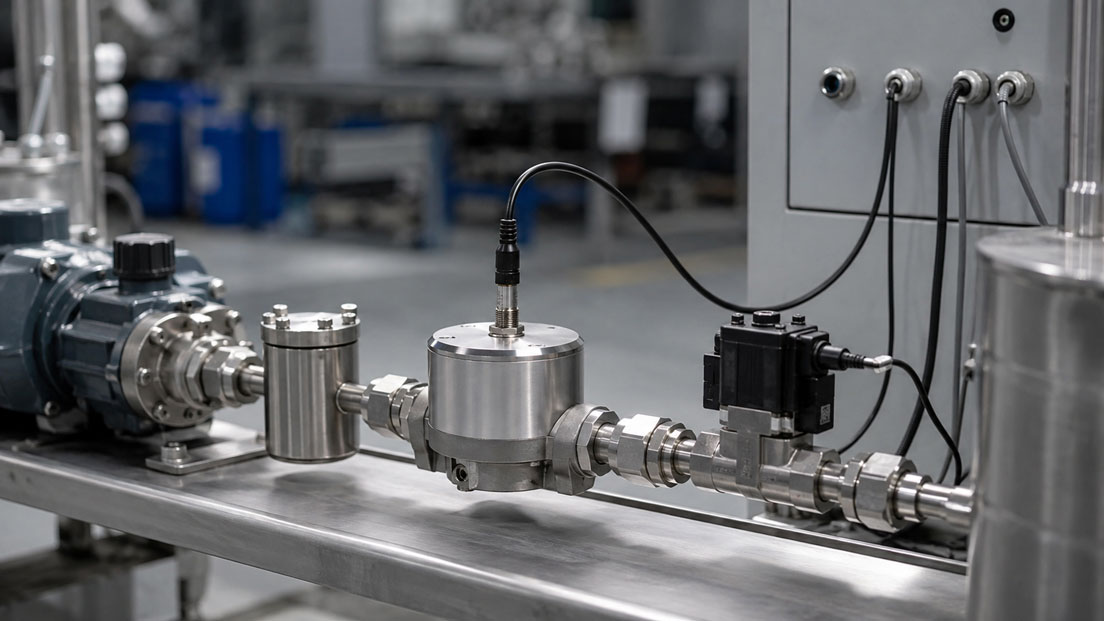
Oval gear meters are particularly well suited for measuring and dosing the volumetric flow of oils, resins, paints, additives, fuels and other viscous liquids. Unlike many flow-dependent measurement methods, they measure defined partial volumes and can therefore achieve high repeatability even at low flow rates.
In practice, however, selecting the meter solely according to the pipe connection and maximum flow rate is not sufficient. The actual viscosity at start-up and operating temperature, the available pump pressure, the pressure loss across the entire measuring line, the minimum flow rate, the pulse resolution and the properties of the medium must be considered together.
An undersized oval gear meter can generate such a high pressure loss with cold resin that the pump can no longer achieve the required flow rate. An oversized meter often reduces the pressure loss, but may operate below its permissible measuring range for small dosing quantities and provide too few pulses for accurate shut-off.
An overview of suitable devices can be found in the ICS category Gear Flow Sensors and Oval Gear Meters. Additional measuring principles and product groups are summarised under Flow Measurement Technology.
Table of Contents
- How does an oval gear meter work?
- Determine viscosity at all temperatures
- Correctly size pressure loss and nominal diameter
- Consider minimum flow and starting torque
- Distinguish between pulsation and pulse output
- Calculate dosing accuracy and pulse resolution
- Consider particles, filters and abrasion
- Check temperature, materials and seals
- Systematic selection and verification procedure
- Typical sizing and operating errors
- Practical example: Dosing resin in a mixing system
- Which products and solutions are suitable?
- Conclusion
- Frequently asked questions
How does an oval gear meter work?
Oval gear meters belong to the positive displacement meter category. Two intermeshing oval gears rotating in opposite directions are located inside the measuring chamber housing. Defined volumes of liquid are enclosed between the oval gears and the housing wall and transported from the inlet to the outlet.
Each revolution corresponds to a defined volume. A magnetic, inductive or other suitable pulse transmitter detects the movement of the oval gears. The total volume is calculated from the number of pulses, while the pulse frequency corresponds to the instantaneous volumetric flow rate.
A K-factor is normally used for signal evaluation:
Volume = Number of pulses / K-factor
The K-factor may, for example, be specified in pulses per litre. For precise dosing applications, the K-factor assigned to the specific version and calibration should be used. A general nominal value for an entire product family is not always sufficient for accurate dosing.
The positive displacement principle offers particular advantages for homogeneous and sufficiently clean liquids. Long inlet runs are not required for many designs. Nevertheless, the pipe must remain completely filled, gas bubbles must be avoided and the manufacturer-specific installation instructions must be observed.
Determine viscosity at all temperatures
Viscosity is one of the most important sizing parameters. It affects the pressure loss, start-up behaviour, internal leakage, achievable lower measuring range limit and the load on the moving components.
A distinction must be made between:
- dynamic viscosity in mPa·s,
- kinematic viscosity in mm²/s or cSt,
- viscosity at normal processing temperature,
- viscosity during a cold start and after the system has been shut down.
Dynamic and kinematic viscosity can be converted into one another by taking the density into account:
Kinematic viscosity ν = Dynamic viscosity η / Density ρ
When η is expressed in mPa·s and ρ in g/cm³, ν is approximately obtained in mm²/s.
The viscosity of many oils, resins and paints changes significantly with temperature. A medium may flow without difficulty at 60 °C, but after cooling overnight to 15 °C may reach several times its normal operating viscosity. The oval gear meter must therefore be sized not only for stable production conditions, but also for cleaning, start-up and shutdown.
| Operating condition | Viscosity to be checked | Possible effect |
|---|---|---|
| Cold system start | Maximum expected viscosity | High starting torque and high pressure loss |
| Normal operation | Viscosity at process temperature | Determination of measuring range and calibration point |
| Maximum temperature | Lowest operating viscosity | Increased internal gap losses at low flow rates |
| Cleaning | Viscosity of the cleaning medium | Changed measurement deviation or impermissible rotational speed |
For non-Newtonian media, specifying a single viscosity value is often insufficient. Thixotropic paints, filled resins or shear-thinning products may exhibit different flow behaviour depending on shear rate, temperature and standing time. In such cases, rheological data and practical operating tests should be included in the sizing process.
Correctly size pressure loss and nominal diameter
The medium must move the oval gears and flow through the narrow gaps in the measuring chamber. The pressure loss therefore increases as the flow rate and viscosity rise. Its actual value depends on the meter size, internal clearances, bearing arrangement, materials and specific design.
A general pressure loss value cannot be specified for all oval gear meters. The decisive values are the manufacturer’s pressure loss curves or sizing data for the intended meter size and viscosity.
The entire measuring line must be considered for the system:
Δptotal = Δpmeter + Δpfilter + Δpvalves + Δppipework
The pump must overcome this pressure loss in addition to the required process pressure. For highly viscous media, filters and pipework can cause a pressure loss that is equal to or even greater than that of the actual flow meter.
The hydraulic power required solely to overcome a pressure loss can be estimated as follows:
Phyd [kW] = Δp [bar] × Q [L/min] / 600
The actual power requirement of the pump will be higher due to its efficiency.
Do not automatically select the smallest meter size
A small meter size often provides high pulse resolution and a low minimum flow rate. At high viscosity, however, it can generate a disproportionately high pressure loss. A larger meter size often reduces the pressure loss, but may increase the lower measuring range limit and reduce the number of pulses per litre.
The appropriate meter size is therefore a compromise between:
- maximum and minimum flow rate,
- viscosity under all operating conditions,
- permissible pressure loss,
- available pump pressure,
- required pulse resolution,
- dosing quantity and shut-off dynamics.
It must also be checked whether the pressure downstream of the meter remains sufficiently above the vapour pressure of the medium. A high local pressure drop can promote degassing or cavitation. Gas bubbles impair the measurement and can result in unstable operation.
Consider minimum flow and starting torque
Every oval gear meter has a permissible measuring range. Below the minimum flow rate, the pressure differential and available torque may not be sufficient to move the oval gears uniformly. The meter may stop, start intermittently or generate irregular pulses.
At low viscosity, internal gap losses have a greater effect at the lower end of the measuring range. Some of the liquid may flow past the moving elements without being fully measured as a defined partial volume. A higher viscosity often improves internal sealing, but at the same time increases friction, starting torque and pressure loss.
Starting after extended shutdown periods is particularly critical. Resins, paints or adhesives may become more viscous, form deposits or partially cure. The pump must not build up pressure indefinitely against a blocked meter. Suitable pressure limitation and a start-up sequence adapted to the process are therefore important.
Distinguish between pulsation and pulse output
With oval gear meters, the term pulsation can describe three different effects:
| Type of pulsation | Cause | Effect |
|---|---|---|
| Process pulsation | Piston, diaphragm or dosing pump | Fluctuating instantaneous flow and varying torque |
| Mechanical periodicity | Geometry and rotational movement of the oval gears | Minor periodic fluctuations in torque and pressure |
| Electrical pulses | Pulse transmitter of the meter | Discrete output signal for volume and flow calculation |
A strongly pulsating pump can cause the meter to alternate between high and low rotational speeds within a short period. This is often less problematic for the totalised volume than for the instantaneous flow indication. However, the indicated value may become unstable if the evaluation system calculates a short-term flow rate from only a few pulses.
Suitable averaging in the PLC or evaluation electronics can resolve this issue. Strong averaging stabilises the indicated value, but delays the response to actual flow changes. For dosing applications, shut-off should therefore preferably be based on the counted pulse quantity and not solely on a smoothed analogue value.
For pronounced pump pulsation, a suitable pulsation damper may be useful. Its materials, volume and installation position must be compatible with the medium and the process. It must not cause the dosing process to continue uncontrollably due to elastically stored liquid volume.
If the flow direction can reverse temporarily, it must be checked whether the meter and its electronics can detect the direction. A simple single-channel pulse output may not be able to distinguish reverse movement from forward movement.
Calculate dosing accuracy and pulse resolution
When evaluating pulses, the K-factor determines how finely a dosing quantity can be resolved. The volume per pulse is:
Vpulse = 1 / K-factor
With a K-factor of 400 pulses per litre, one pulse corresponds to a volume of 2.5 ml. A set quantity of 1.2 litres therefore requires 480 pulses.
In this example, the theoretical resolution limit of one pulse is:
1 / 480 × 100% = 0.21% of the dosing quantity
The actual dosing deviation also depends on the calibration, valve, PLC cycle time, flow velocity, pressure, elasticity of hoses and pipework and the overrun between the shut-off command and complete valve closure.
The following functions are therefore often required for accurate dosing:
- coarse dosing at a high flow rate,
- fine dosing at a reduced flow rate,
- pre-shut-off point before the target quantity is reached,
- automatic overrun correction,
- monitoring of minimum and maximum pulse frequency,
- detection of missing pulses while the pump is running.
The pulse output is generally particularly suitable for total volume measurement. A 4–20 mA signal may be useful for trend indication and control, but does not automatically provide the same direct volume resolution for small batches as pulse counting.
Consider particles, filters and abrasion
The moving oval gears and narrow clearances are sensitive to hard foreign particles. Metal chips, sand, cured paint residues or abrasive fillers can block the oval gears, damage surfaces or cause wear to the bearings and housing.
A filter upstream of the meter is therefore useful in many applications. However, the required filter fineness must not be specified as a general value. It depends on the permissible particle sizes of the specific meter, the medium, nominal diameter and process.
The filter itself must also be included in the pressure loss calculation. With viscous media or increasing contamination, its differential pressure can rise significantly. A readily accessible installation point, a defined cleaning strategy and, for critical applications, differential pressure monitoring are recommended.
For filled resins, paints or media containing intentional solids, a filter may not be a suitable solution. It could alter the composition of the product or become blocked quickly. In this case, it must be verified whether the oval gear meter is explicitly approved for the particle size, concentration and abrasiveness involved. Otherwise, a different measuring principle may be more suitable.
Check temperature, materials and seals
Temperature affects more than viscosity. It also determines the permissible load on the housing, oval gears, bearings, pulse transmitters and seals. The maximum permissible process temperature may depend on the selected material and electronics version.
At least the following components must be considered when checking material compatibility:
- measuring chamber and housing,
- oval gears, shafts and bearings,
- seals and O-rings,
- process connections,
- any coatings or plastics,
- cleaning and flushing media.
A seal may be resistant to the actual process product, but may swell or become brittle due to a solvent used during cleaning. Temperature changes can also influence its service life. Chemical compatibility must therefore be checked for all media and temperatures throughout the complete operating cycle.
If trace heating or a heating jacket is to be used, uniform temperature control must be ensured. Local overheating can alter the product or damage the seals. After a shutdown, the meter should be heated sufficiently before the pump is started at full capacity.
Systematic selection and verification procedure
- Describe the medium completely: Record the product name, composition, density, lubricating properties, particles, abrasiveness and chemical characteristics.
- Define the viscosity range: Specify values at the minimum start-up temperature, normal operating temperature and maximum temperature.
- Determine the flow range: Distinguish between minimum flow, normal flow, maximum flow and possible short-term peaks.
- Define the dosing quantity: Specify the smallest and largest batch, permissible deviation and required dosing time.
- Check the pressure conditions: Record the pump curve, inlet pressure, back pressure and permissible total pressure loss.
- Compare meter sizes: Compare the pressure loss, minimum flow and pulse resolution of several meter sizes.
- Select the materials: Check the housing, oval gears, bearings and seals against the process and cleaning media.
- Define the signal and evaluation: Select pulse, PNP, frequency, analogue signal or electronics to suit the PLC and dosing function.
- Plan the installation: Consider filtration, shut-off, venting, pressure limitation, grounding and maintenance accessibility.
- Coordinate the calibration: Where possible, calibrate under conditions that correspond to the viscosity, temperature and flow rate of the actual process.
Typical sizing and operating errors
| Error | Possible consequence | Suitable measure |
|---|---|---|
| Only considering viscosity at operating temperature | Meter does not start during a cold start | Check the maximum viscosity at the minimum temperature |
| Selecting the meter by pipe thread rather than measuring range | Excessive pressure loss or insufficient resolution | Select the meter size based on flow rate, viscosity and dosing quantity |
| Not considering filter pressure loss | Pump does not achieve the required flow rate | Calculate the filter in both clean and contaminated condition |
| Incorrect pulse value parameterisation | Incorrect total volume | Use the K-factor from the calibration and device configuration |
| Using an analogue instantaneous flow signal for small dosing quantities | Inaccurate batch shut-off | Count pulses and compensate for overrun |
| Gas bubbles or an empty pipe | Unstable operation and unreliable measured values | Fill and vent the pipe and ensure sufficient pressure |
| Abrasive particles in the medium | Wear or blockage | Check approval, adapt filtration or select a different measuring principle |
| Meter not flushed after operation | Cured residues block the oval gears | Implement a defined flushing procedure compatible with the materials |
| Impermissible dry running or purging with compressed air | Overspeed or bearing damage | Only perform this if explicitly approved by the manufacturer |
Practical example: Dosing resin in a mixing system
A mixing system is required to dose 1.2 litres of liquid resin per batch. The normal flow rate is 2.5 L/min. At 55 °C, the resin has a dynamic viscosity of approximately 800 mPa·s. After an extended shutdown, the temperature can fall to 18 °C, causing the viscosity to rise to more than 5,000 mPa·s.
A compact meter selected initially would be sufficient for normal operation. However, its permissible viscosity and pressure loss during a cold start would not be adequate. The system would start only slowly or reach the pump’s pressure limitation.
The solution is not simply to use a larger process connection. First, it is specified that the heated pipework and meter must reach a minimum temperature before start-up. Two meter sizes are then compared on the basis of their pressure loss curves, minimum flow rates and K-factors.
The selected version provides 400 pulses per litre. At 2.5 L/min, this produces a pulse frequency of:
f = 400 pulses/L × 2.5 L/min / 60 = 16.7 Hz
For 1.2 litres, 480 pulses are counted. The volume per pulse is 2.5 ml. With a valve closing time of 80 ms, approximately 3.3 ml continues to flow after the shut-off command if the flow rate remains unchanged.
This overrun is greater than one pulse and must be taken into account in the PLC programming. The control system therefore ends coarse dosing early and performs the final part of the batch at a reduced flow rate. The actual overrun is determined during commissioning and stored as a correction value.
A filter suitable for the resin is also installed upstream of the meter. Its pressure loss is considered at maximum viscosity and for the intended contamination level. After each production run, the measuring line is flushed with an approved cleaning medium before the resin can cure.
Which products and solutions are suitable?
HySense® QO400
The HySense® QO400 is a compact oval gear flow sensor with a PNP output and M12 connection. Depending on the meter size, the product family covers flow ranges from 0.03 to 660 L/min. General specifications include viscosity up to 3,000 mPa·s, measurement accuracy of ±0.5% of the measured value, medium temperatures up to 125 °C and operating pressures up to 68 bar. The specific combination of limits must be checked for the selected version.
QO400 HySense® Precision Oval Gear Flow Sensor
The QO400 HySense® operates according to the positive displacement principle and is equipped with female threaded connections according to DIN ISO 228. It is suitable for compact measuring points in mechanical engineering, factory automation and process instrumentation, provided that the medium and material compatibility are suitable.
Flowal® Plus Oval Gear Meter
The Flowal® Plus oval gear meter combines a mechanical measuring element with a pulse transmitter or multifunction electronics. Different material combinations allow adaptation to a variety of industrial, chemical or corrosive liquids. The measuring range, viscosity, materials and electronics must be configured to suit the application.
Flowal® OF Oval Gear Meter
The Flowal® OF oval gear meter is a compact, flange-mounted version with multifunction electronics. It is intended for Newtonian, non-abrasive liquids such as oils, greases, fuels, solvents, paints and coatings. The product page specifies flow rates from 1 to 700 L/min and measurement accuracy of ±0.5% of the measured value. Suitability must be checked separately for non-Newtonian or particle-laden products.
ICS Schneider Messtechnik provides support in selecting the measuring range, meter size, materials, seals, output signal and evaluation electronics, as well as coordinating viscosity, pressure loss and calibration conditions.
Conclusion
Oval gear meters are a precise and cost-effective solution for many clean, homogeneous and viscous liquids. Their main strengths are direct volumetric measurement and good resolution of small quantities.
Reliable operation, however, requires viscosity, temperature, minimum flow and pressure loss to be considered together. The cold system start must not be overlooked. Filters, valves and pipework must be included in the pressure loss calculation alongside the meter itself.
For dosing applications, the K-factor, pulse resolution, valve closing time and overrun are at least as important as the specified measurement accuracy. Particles, abrasion, gas bubbles and curing residues must be considered during the planning stage. The best meter size is therefore not automatically the smallest or largest one, but the version that reliably covers the entire operating range.
Frequently asked questions about oval gear meters for viscous media
Are oval gear meters completely independent of viscosity?
No. Although the measuring principle is comparatively robust against viscosity changes, viscosity still affects pressure loss, starting torque, internal gap losses and the permissible flow limits. For precise measurements, calibration should be carried out as close as possible to the actual process conditions.
Can an oval gear meter measure very small quantities of oil?
Yes, provided that the measuring range and pulse resolution match the dosing quantity. For very small batches, the volume per pulse, valve closing time and pipework overrun must be taken into account.
Why does the pressure loss increase with cold oil or resin?
As the temperature falls, the viscosity of many liquids increases. This increases internal friction in the meter, filter and pipework. The pump requires more pressure to generate the same flow rate.
Should a larger meter always be selected for highly viscous media?
Not necessarily. A larger meter size can reduce the pressure loss, but may also have a higher minimum flow rate and lower pulse resolution. Both meter sizes must be compared using the complete operating data.
Does an oval gear meter require a filter?
For media that may contain foreign particles, a suitable filter is often advisable. However, the filter fineness and pressure loss must be compatible with the specific meter and medium. An oval gear meter may be unsuitable for intentional solids or abrasive fillers.
Can the meter be installed directly downstream of a dosing pump?
This is generally possible, but pump pulsation, available inlet pressure, pressure loss and possible reverse flow must be checked. In the case of strong pulsation, adjusted averaging or a suitable pulsation damper may be required.
Is the pulse output more accurate than a 4–20 mA signal?
Pulse counting is often advantageous for measuring a dosing quantity because each pulse corresponds to a defined volume. A 4–20 mA signal is particularly suitable for instantaneous flow indication and control. However, the achievable overall accuracy always depends on the sensor, electronics, parameterisation and process.
What must be considered when cleaning resin or paint systems?
The measuring chamber must be flushed before residues can cure. The cleaning medium, temperature and flushing duration must be compatible with the housing, oval gears, bearings and seals. Dry running or purging with compressed air is only permissible if explicitly approved by the manufacturer.