


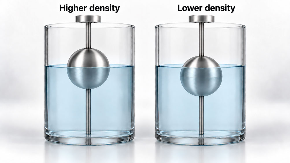
A float switch works correctly during commissioning with water. After a change to a less dense process medium, however, it indicates the upper level limit later. Alternatively, a continuous level transmitter displays a different value after a temperature change, even though an independent reference measurement detects hardly any change in level. In both cases, a change in the float’s immersion depth may be the cause.
In float level measurement, buoyancy links the liquid surface to the position of a mechanical body. Contacts, reed measurement chains and magnetostrictive sensors then detect its position. A change in density alters this relationship. An electrically valid signal can therefore deviate from the actual liquid level.
Three questions are crucial to the assessment: Does the selected configuration float reliably throughout the operating range? How far does the float’s position shift relative to the surface? And what consequences does this shift have for indication, pump control or alarms? This article explains the relationships and shows how to distinguish density effects from installation errors, friction and incorrect parameter settings.
Contents
- Clearly Define the Measurement Task
- What the Different Designs Measure
- Understand Buoyancy and Immersion Depth
- Determine the Direction of the Switching Level Shift
- A Worked Example for Changing Density
- Correctly Assess Limit Density and Operating Margins
- Identify Density Changes During Operation
- Distinguish Density Effects from Viscosity, Deposits and Foam
- Account for Interfaces and Stratified Media
- The Importance of Vessel Geometry
- Check Installation, Freedom of Movement and Dead Zones
- Understand Additional Density Effects in the Bypass
- Put Continuous Measurement and Resolution in Context
- Define the Switch Point, Reset Point and Hysteresis
- What Parameter Settings and Density Correction Can Achieve
- Test the Measurement Point Under Realistic Conditions
- Systematically Diagnose Typical Observations
- Design Alarm Limits and Response Margins
- Select a Suitable Solution for the Density Range
- Suitable Level Measurement Technology from ICS Schneider
- Conclusion: Assess the Entire Measurement Chain
- Frequently Asked Questions About Float Level Measurement with Changing Density
1. Clearly Define the Measurement Task
A level limit indication, continuous liquid level indication and inventory measurement involve different requirements. A float switch is intended to actuate a contact at a defined liquid level. A continuous sensor is intended to represent the liquid level over a measuring span. Volume or mass indication requires additional calculation steps.
Before selecting an instrument, it is therefore necessary to define the deviation the application can tolerate. In a large storage vessel, a few millimetres may be uncritical for operational indication. In a shallow dosing vessel, near an overflow or within a narrow pump switching band, the same shift can be significant. The assessment must relate to the actual process.
Every comparison also needs the same reference: the height above the vessel bottom, the distance below a sealing face or the position of a liquid boundary. A change in the indication can only be meaningfully assessed once the reference plane, direction of measurement and operating condition have been documented.
2. What the Different Designs Measure
In a vertical magnetic float switch, a float moves along a guide tube. Its magnet actuates reed contacts arranged inside the tube. A reed level transmitter, by contrast, uses a measurement chain with many switching positions. A magnetostrictive transmitter determines the magnet position using a time-of-flight method. All these float-based configurations share the same initial step: the float first assumes a mechanical position.
| Design | What Is Evaluated | Density Effect |
|---|---|---|
| Vertical magnetic float switch | Reaching a defined magnet position at the contact | The actual liquid level at switching changes with the immersion depth. |
| Side-mounted lever float switch | A predefined lever or switching position | Buoyancy, lever geometry and any opposing forces jointly determine the switching level. |
| Reed level transmitter | Float position detected by a stepped resistance measurement chain | Position resolution and the density-dependent relationship to the surface are separate influences. |
| Magnetostrictive level transmitter with a float | Position of the float magnet | High position resolution does not eliminate the change in immersion depth. |
| Magnetic bypass level indicator | Magnet position of a float in a side-mounted chamber | In addition to immersion depth, different conditions in the vessel and bypass can have an effect. |
The following simple equations apply to a freely moving, vertically guided float without significant additional forces. For lever floats, cable-suspended float switches or displacer systems, the respective mechanics must be considered separately. Their behaviour cannot be derived directly from the immersion depth of a freely floating body.
3. Understand Buoyancy and Immersion Depth
The hydrostatic buoyant force equals the weight of the displaced liquid. For a homogeneous liquid and negligible buoyancy from the gas phase, the following approximation applies:
FA = ρ · g · Vdisplaced
Here, ρ denotes the liquid density, g the acceleration due to gravity and Vdisplaced the volume of liquid displaced. In static floating equilibrium, this force equals the weight of the float:
ρ · g · Vdisplaced = mS · g
Vdisplaced = mS / ρ
If the density decreases while the displaced volume initially remains unchanged, the buoyant force decreases. The float then becomes more deeply immersed. In the new equilibrium, buoyancy once again supports its weight. The decisive change is therefore the float’s position relative to the liquid surface.
The number of millimetres required depends on the float’s shape. For an effective cross-sectional area Aeff that is constant from the bottom of the float to the liquid surface, the approximate relationship is t = mS / (ρ · Aeff). For spheres, rounded ends and other contours, the cross-sectional area changes with immersion depth. In these cases, the manufacturer’s characteristic curves or the actual volume geometry are decisive. For annular floats, the liquid-filled central opening must not be counted as part of the float’s liquid-displacing volume.
4. Determine the Direction of the Switching Level Shift
To establish the direction of the shift, the liquid level h is measured upwards from the vessel bottom. The immersion depth t extends from the bottom of the float to the liquid surface. The effective magnet reference point is located at a fixed distance a above the bottom of the float. Its height is then:
zM = h − t + a
If a fixed contact switches at magnet position zS, the following relationship applies to the same switching event and the same direction of movement:
hS = zS + t − a
Greater immersion depth shifts the actual liquid switching level upwards. At a lower density, the liquid must therefore reach a greater height for the more deeply immersed float magnet to reach the same switching position. An upper level limit may consequently be indicated later during filling.
At an unchanged actual liquid level, the effect on a continuous indication is the opposite: the magnet sits lower. An indication adjusted to the original density and scaled as liquid level will therefore show a correspondingly lower value. At a higher density, these changes are reversed. If an installation dimension is specified from top to bottom, the numerical change in that dimension has a different sign. The assessment should therefore always also describe the physical direction of the level shift.
5. A Worked Example for Changing Density
Consider an idealised float with a mass of 80 g, a constant effective displacement cross-sectional area of 20 cm² and a height of 80 mm. Buoyancy from the gas phase, surface tension, friction and deformation are neglected. The entire immersion depth under consideration lies within the region of constant cross-sectional area. These assumptions describe a calculation model rather than a specific product configuration.
At 1,000 kg/m³, equivalent to 1.00 g/cm³, the float must displace 80 cm³. This gives an immersion depth of 40 mm. At 800 kg/m³, it requires a displaced volume of 100 cm³ and is immersed to a depth of 50 mm.
| Liquid Density | Displaced Volume | Immersion Depth | Change in Actual Switching Level Relative to 1,000 kg/m³ |
|---|---|---|---|
| 1,000 kg/m³ | 80.0 cm³ | 40.0 mm | 0.0 mm |
| 900 kg/m³ | 88.9 cm³ | 44.4 mm | +4.4 mm |
| 800 kg/m³ | 100.0 cm³ | 50.0 mm | +10.0 mm |
| 750 kg/m³ | 106.7 cm³ | 53.3 mm | +13.3 mm |
Under these model conditions, a switching level designed to be 600 mm at the reference density would be 610 mm at 800 kg/m³. A continuous indication adjusted to the reference density would, by contrast, display 590 mm when the actual liquid level is 600 mm.
Manufacturer documentation also provides such relationships: for the KSR V44A cylindrical float described in the relevant document, an immersion depth table specifies 35 mm at 1,000 kg/m³ and 43 mm at 800 kg/m³. The difference for this configuration is 8 mm. Such values may only be applied to the corresponding float.
A density change of 20 % therefore does not imply a general error of 20 % of the level measuring range. The deviation results from the float’s mass, shape, density conditions and reference position. The measuring range alone does not describe it.
6. Correctly Assess Limit Density and Operating Margins
The specified limit density describes an operating limit of the particular float under the defined conditions. It must be distinguished from the permissible switch point or indication deviation. A float may be fundamentally suitable for the medium while still exhibiting a change in immersion depth that is significant for the application.
The definition of limit density must also be checked. In WIKA data sheet LM 30.01, the corresponding float tables refer to 85 % immersed float volume; the nominal density stated there refers to 50 %. The tabulated limit density is therefore not simply the theoretical density at which a fully submerged body would just be supported. The definition must be checked for the manufacturer and configuration concerned.
The lowest liquid density that actually occurs during operation must be considered. Possible changes caused by deposits, liquid entering a damaged hollow body, friction or restricted movement must also be taken into account. A blanket percentage margin does not suit every design. A suitable float configuration with a substantiated operating margin and an acceptable change in position is required.
Furthermore, the lowest limit density within a product family does not automatically apply to every available float. Material, dimensions, pressure resistance and temperature range must match the specific combination selected.
7. Identify Density Changes During Operation
A density value at room temperature is often insufficient for a heated process. Density values are needed for the relevant temperature and composition ranges. For many liquids, density decreases as temperature increases. Recipe changes, concentration changes, solvent proportions or the ingress of other media can cause further changes.
Normal operation, start-up, cooling, product changeovers and, where applicable, cleaning should be considered separately during design. It must be established which function the measuring point is required to perform in each condition. A substitute medium used for functional testing requires a documented assessment of its differing properties.
Temperature can also change the actual level: when an existing quantity of liquid expands, its volume increases. At an unchanged mass, V = m / ρ applies to a homogeneous medium. The resulting actual level change can be superimposed on the density-related error in float position. A correlation with temperature alone therefore does not prove a measurement error.
At high pressures, the mechanical pressure resistance of the float and, where relevant, buoyancy in the gas phase must also be considered. If the gas density is significant, the simplified calculation using liquid density alone is no longer sufficient. Such conditions require application-specific design.
8. Distinguish Density Effects from Viscosity, Deposits and Foam
Density and viscosity have different effects. In the ideal static case, density determines the required displacement volume. Viscosity primarily affects the dynamics of movement. A measuring point that reaches a plausible value after sufficient settling time but noticeably lags during rapid filling should therefore be checked for flow resistance, friction along the guide tube and hydraulic delay.
Deposits can combine several effects: they change the mass and contour of the float and can narrow the clearance around the guide tube. A damaged hollow body may become heavier as liquid enters it. This type of fault resembles a density change but may persist after returning to the original medium. The condition and freedom of movement of the float therefore form part of the diagnosis.
Gas bubbles and foam require their own assessment. A float designed to detect the liquid level does not necessarily detect the top of a light foam layer. Strong aeration, adhering bubbles or an agitated two-phase zone can influence float movement. A single liquid density value represents these conditions only to a limited extent.
Wetting and surface tension can also cause additional forces, particularly with small floats and narrow clearances. A larger float alone does not reliably resolve such installation or medium-related problems.
9. Account for Interfaces and Stratified Media
With two immiscible liquids, the first step is to establish whether the upper surface or the interface is to be measured. A surface float must float reliably on the upper phase. A float designed for interface measurement, by contrast, sinks through the lighter upper phase and is supported by the denser lower phase.
For a float completely surrounded by the two liquids, the buoyant force consists of contributions from both phases. For this operating principle to work, its average density must lie between the densities of the two liquids. If either density changes, the position relative to the interface changes. When the density difference is small, this relationship is particularly sensitive.
The density ranges of both phases and the smallest relevant density difference are therefore required. The thickness of the upper layer, emulsion zones and the possibility of a complete product change are also important. A broad transition zone may not provide a clearly defined interface. An additional electronic channel alone does not make an existing surface float suitable for interface measurement.
10. The Importance of Vessel Geometry
The shape of the vessel does not directly change the ideal buoyancy equilibrium of a freely floating body. It does, however, determine the installation space, flow conditions and operational significance of a level deviation. For a vessel with a constant horizontal cross-sectional area AB, the following applies:
ΔV = AB · Δh
With a vessel cross-sectional area of 2 m², a level shift of 10 mm already corresponds to 20 l. This is a geometric conversion assuming a constant cross-sectional area. For a horizontal cylindrical tank, a conical vessel bottom or a vessel with internal components, however, the additional volume depends on the current level. Here, the vessel characteristic curve V(h) is required.
For a mass indication with a homogeneous liquid, the relationship m = ρ · V must also be considered. An accurately measured float position alone is not sufficient. If liquid level, volume and mass are displayed by the same controller, the density correction of the float position and the use of density for the mass calculation must remain separately traceable.
11. Check Installation, Freedom of Movement and Dead Zones
A float must be able to move freely over its entire required travel. Check the clearance from the vessel wall, nozzle geometry, guide tube alignment, internal components and the effects of the inlet or agitator. Lateral flow forces can press a guided float against the tube and impede its movement.
A lower density also changes the position of the entire float body relative to the desired liquid switching level. Stops and dead zones inherent in the design must therefore be compatible with the actual immersion position. A nominally suitable measuring range does not guarantee that all intended limit levels are mechanically reachable.
For long guide tubes or those installed at an angle, the permissible installation orientation and support requirements must be taken from the specific documentation. If a float is removed for installation, its orientation, magnet position and stop position must subsequently be restored. A replacement float must be selected according to its complete configuration; a similar outside diameter does not establish interchangeability.
A protective tube or stilling well can reduce flow effects. However, its connection to the process must allow the levels to equalise sufficiently quickly. Otherwise, an additional delay arises, which must be taken into account particularly for alarm functions.
12. Understand Additional Density Effects in the Bypass
In a bypass level indicator, the float moves in a chamber connected to the side of the vessel. Two effects must be checked separately here: the immersion depth in the chamber medium and the possible difference between the chamber level and the vessel level.
For a simplified static case with equal pressures in the gas spaces, negligible gas density and a homogeneous liquid in each, pressure equilibrium at the lower connection gives:
ρvessel · Hvessel = ρbypass · Hbypass
Both heights are measured from the same reference plane at the lower connection to the respective surface. If, for example, the medium in the bypass is colder and therefore denser than in the vessel, the actual bypass level may be lower. In addition, the density there changes the float’s immersion depth. The two contributions can reinforce each other or partially counteract each other.
After a product change, a different composition may also remain in a chamber with poor circulation. Isolated or blocked connections, gas accumulation and temperature differences must therefore be checked before any offset correction. The simple equation does not cover arbitrary connection arrangements or two-phase conditions.
Agreement between a local magnetic display and a remote signal initially confirms only that both detect the same float in a similar way. A common hydraulic or mechanical error may be present in both indications at the same time.
13. Put Continuous Measurement and Resolution in Context
High-resolution electronics can detect the position of the float magnet very accurately. However, the liquid surface level can only be determined from this position together with the corresponding immersion depth of the float. The resolution of the position measurement principle therefore does not describe the overall measurement uncertainty of the liquid level.
With a reed measurement chain, the fixed measurement increments influence the spatial resolution. A downstream transmitter can, for example, generate a signal of 4 … 20 mA from this. Scaling changes neither the contact spacing nor the immersion depth. With magnetostrictive evaluation, these reed increments are no longer part of the measuring principle; the density-dependent float position remains part of the measurement chain.
A sound assessment therefore considers several contributions: position measurement, mechanical installation, float characteristic curve, density range and dynamic effects. If only the current signal is tested with a simulator, this verifies the electronic processing. It does not yet demonstrate the relationship to the actual liquid surface.
14. Define the Switch Point, Reset Point and Hysteresis
An unambiguous switch point specification includes the reference plane, measurement direction, direction of movement, contact function and reference conditions. It must also be clear whether the specified dimension describes the actual liquid switching level or a position determined by the design. Manufacturers may already take the required immersion correction into account in their design.
For the specification of certain float switches, WIKA describes, for example, installation from above, dimensions measured from the sealing edge, a rising level and a reference density of 1.00 g/cm³. The agreed conditions are decisive for the specific order. They must not be silently replaced during a subsequent test with a different medium.
Hysteresis is the difference between the corresponding switching and reset levels. It must be documented separately from the density-dependent offset. Under idealised conditions, a density change can shift both levels similarly while the distance between them remains largely unchanged. Additional friction or adhesion, by contrast, can also change this distance.
For pump control, a distinction must also be made between the instrument’s inherent hysteresis and the deliberately specified distance between the pump start and stop limits. This operational distance must not be inferred from a general assumption about reed contact hysteresis.
15. What Parameter Settings and Density Correction Can Achieve
For a continuous signal, an offset correction can adjust the indication to a known reference condition. However, a one-time adjustment only compensates for the offset present in that condition. If the density subsequently changes, a deviation may occur again.
A variable correction requires a suitable float characteristic curve, sufficiently well-known current density and evaluation designed for that purpose. A temperature value is sufficient only if the relationship between temperature and density is known for the specific medium, including its composition. Automatic density compensation must not be assumed merely because a digital interface is available.
A simple reed contact installed in a fixed position has no freely configurable analogue zero point. Changes to PLC scaling do not shift its actual response level. A mechanical modification, a different float or a changed contact position require a design that permits this and a subsequent function test.
The entire relationship must also be correct for a software limit derived from the analogue signal. A correction can address a known, reproducible density-dependent offset. It cannot restore a functioning measurement when the float sticks, buoyancy is insufficient or the bypass chamber is isolated.
16. Test the Measurement Point Under Realistic Conditions
A meaningful test relates the actual liquid level to the mechanical behaviour and the electrical result. Simply moving the float by hand tests essential parts of the switching function, but does not reproduce buoyancy in the operating medium.
- Document the configuration and reference: Record the instrument, float type, installation dimensions, stops, reference density, contact functions and current parameter settings.
- Define the operating conditions: Establish the relevant density and temperature limits and product changes. Only use substitute media once the applicability of the results to the operating medium has been assessed.
- Establish a suitable level reference: Select an independent reference with known density and temperature effects of its own. An uncompensated hydrostatic measured value does not automatically provide a correct comparison when density changes.
- Record static switching and measured values: Raise and lower the level slowly, allow conditions to settle, and record the actual height, temperature, density, indication and contact state together.
- Test the dynamic behaviour: Assess the intended operating conditions with their filling and emptying rates, and determine the delay compared with the static test.
- Verify the complete function: Check signal processing, alarm indication and the associated plant response in accordance with the defined test procedure, and document the approved settings.
A comparison using at least two representative densities reveals a systematic offset. Further test points may be necessary if the float geometry is highly nonlinear or the operating range is wide. The key question is whether the intended extreme conditions are adequately covered.
Mechanical checks and interventions must be carried out under the safe plant conditions specified for this work and in accordance with the relevant operating instructions. After replacing a float or changing the mounting orientation, the relationship to the liquid height must be checked again.
17. Systematically Diagnose Typical Observations
A density problem often appears as a reproducible relationship between operating conditions and level offset. A float that moves with difficulty along its guide is more likely to cause delays, jumps or altered reset points. These patterns provide clues, but do not replace testing of the actual installation.
| Observation | Possible cause | Useful check |
|---|---|---|
| After changing to a lower-density medium, the upper level limit is signalled at a higher actual level. | Greater immersion depth at lower density. | Compare the operating density and actual switching level with the reference conditions and float characteristic curve. |
| At the same reference level, the continuous indication shifts reproducibly with the medium. | Density-dependent offset of the magnet. | Record the raw signal, reference level and density together under settled conditions. |
| The deviation increases during rapid filling and subsides when filling stops. | Viscous delay, restricted level equalisation or damping. | Compare static and dynamic tests; check connections and filter time settings. |
| The indication jumps or the float only breaks free after a larger level change. | Friction, deposits, tilting and jamming, or contact with vessel internals. | Check the freedom of movement and condition of the float and guide. |
| The offset persists after returning to the original medium. | Deposits, a damaged float, a shifted mounting position or altered scaling. | Compare the mechanical condition and documented settings with the initial state. |
| The local bypass indication and remote signal agree, but the vessel level differs. | A shared float fault or different conditions in the bypass chamber. | Check an independent vessel level reference, temperature, medium exchange and unobstructed connections. |
| The switch point and reset point are unusually far apart. | Additional mechanical hysteresis or an unsuitable configuration. | Compare both directions of movement with the specified values under the same conditions. |
| The float moves, but the expected electrical signal is absent. | A contact, connection or signal processing fault; an unsuitable magnet arrangement. | Check the wiring diagram, float type, contact function and signal path. |
A useful diagnosis separates the actual liquid height, float position, sensor signal and indication or switching response in sequence. This helps identify where in the measurement chain the deviation arises.
18. Design Alarm Limits and Response Margins
For an upper level limit with the vertically guided float considered here, particular attention must be paid to the low operating density: it can shift the actual actuation level upwards. For a lower level limit, a higher density can conversely be unfavourable, because the float is less deeply immersed and only reaches the corresponding contact at a lower actual level during emptying. Both density limits are therefore relevant.
The remaining margin between the alarm and an unacceptable condition must also account for installation deviations, other measurement uncertainties and dynamic delays. For overfill prevention, this includes the quantity of liquid that continues to enter after the level limit has been detected.
For an approximately constant net inflow, a simple estimate is:
ΔVrun-on = Qnet · tresponse
The response time includes the effective delays in measurement, signal processing and plant response up to the end of the run-on period being considered. The volume must be converted into an additional level rise using the vessel geometry. If the inflow varies over time, its time profile must be taken into account.
Stronger damping or a longer debounce time can stabilise fluctuating signals, but may increase the response time. It does not eliminate a static density-dependent offset. For protective functions, the required instrument suitability, independence and testing must be specified separately. Two signals from the same float share its mechanical failure causes.
19. Select a Suitable Solution for the Density Range
Selection starts with the permissible level error and the full density range. The float characteristic curve, mechanical clearance and process conditions are then checked. Only then are the measuring range, signal type and electrical integration considered.
A favourable ratio of float mass to the displacement cross-section at the liquid surface can reduce the sensitivity of immersion depth to density changes. A larger total volume alone is not a sufficient selection criterion. Greater pressure resistance, different materials or a different contour can also change the mass and therefore the behaviour.
If the possible shift, including other influences, remains within the permissible limits, a suitable float solution can be evaluated reliably. For tighter requirements, options include a different float configuration, a validated correction of a continuous measurement or a different measuring principle. The latter’s own medium and installation effects must then be checked in turn.
A useful enquiry therefore states the permissible deviation directly in millimetres or as a functional limit. The description “as accurate as possible” leaves open whether the requirement is for a stable operating indication, a reliable inventory measurement or an alarm switching level that is reliably maintained.
20. Suitable Level Measurement Technology from ICS Schneider
20.1 WIKA FLS: Detecting Defined Level Limits with a Magnetic Float
The WIKA FLS float switches for vertical installation operate with a magnetic float and reed contacts inside the guide tube. Depending on the configuration, multiple switch points and different contact functions are available. For varying densities, particular attention must be paid to specifying the float configuration, reference conditions and actual liquid switching levels.
20.2 WIKA FLR-S, FLR-P and FLR-H: Transmitting Float Position via a Reed Measurement Chain
The WIKA FLR-S, FLR-P and FLR-H reed level transmitters detect the float position using a resistance measurement chain. They are suitable for quasi-continuous level measurement; signal conversion depends on the selected configuration. The assessment considers the increments of the measurement chain and the density-dependent float position separately.
20.3 WIKA FLM-CA: High-Resolution Magnetostrictive Position Measurement
The WIKA FLM-CA magnetostrictive level transmitter combines a compact design with continuous detection of the magnetic float position. It is of interest for applications in which position resolution plays an important role. Selection must also establish how the chosen float behaves relative to the liquid surface at the intended densities.
20.4 WIKA BNA: Local Indication with Optional Signal Transmission
The WIKA BNA bypass level indicator uses a float in a side-mounted chamber and an external magnetic display. Depending on the configuration, transmitters and magnetic switches can be added. When density varies, both the float design and the temperature and condition of the medium in the bypass must be checked.
The Level Measurement Technology category provides an overview of further instruments and measuring principles. The operating limits of the complete instrument configuration are always decisive for a specific selection.
21. Conclusion: Assess the Entire Measurement Chain
Float level measurement requires a reliable relationship between the liquid surface, float position and electrical or visual result. A change in density first changes the required displacement volume. This leads to a different immersion depth and, potentially, a change in the actual switching level.
The application determines whether this shift is acceptable. Minimum density, position resolution, vessel geometry and response margin address different questions. A sound design considers them together and verifies the function under representative operating conditions.
Define the measurement task → Determine operating densities → Check the float characteristic curve → Assess the actual switching level → Account for installation and dynamics → Verify the function
The key practical principle is therefore: a contact that switches reliably only confirms the intended liquid level limit once the float position in the actual operating medium has been taken into account.
22. Frequently Asked Questions About Float Level Measurement with Changing Density
22.1 Why Does the Switch Point Shift Even Though the Contact Is Fixed in Place?
The contact responds to a magnet position. If the liquid density changes, the immersion depth of the float changes. The magnet therefore reaches the fixed contact at a different actual liquid level.
22.2 Does a Lower Density Always Mean a Higher Switching Level?
For the freely moving, vertically guided float considered here, this is approximately true when the switching and movement directions remain the same. Lever-operated floats, additional mechanical forces and other designs require separate consideration. The direction in which dimensions are measured on the drawing must also be clear.
22.3 Does the High-Level Alarm Trigger Earlier or Later in a Lighter Medium?
With the contact position unchanged, the high-level alarm in the vertical arrangement described is reached at a higher actual liquid level during filling. It can therefore trigger later. The resulting reduction in the margin to the maximum permissible level must be assessed.
22.4 Why Can a High Density Be Unfavourable for a Low-Level Limit?
A float has a smaller immersion depth at a higher density. During emptying, it therefore reaches a fixed lower magnet position only at a lower liquid level. For dry-running protection, the remaining liquid reserve must be sufficient under these conditions.
22.5 Is It Sufficient for the Liquid Density to Be Above the Limit Density?
This addresses only one basic design condition. The permissible level deviation, pressure, temperature, material compatibility, freedom of movement and dynamic behaviour must also be suitable. The definition of the limit density must also be taken from the specific data sheet.
22.6 Can a Percentage Level Error Be Derived Directly from a Density Change?
No universal conversion is possible. The density changes the required displaced volume. The float geometry then determines the resulting change in immersion depth. A density difference of, for example, 20 % therefore does not translate into a general error of 20 % of the measuring range.
22.7 Can a Float Switch Tested in Water Subsequently Be Used in Oil?
This depends on the specific type of oil, operating density, viscosity, temperature, material compatibility and instrument configuration. A test in water alone confirms neither the correct immersion depth nor the desired switching level in oil. The applicability of the test to the oil must be assessed.
22.8 Is Magnetostrictive Level Measurement with a Float Independent of Density?
The magnetostrictive evaluation detects the position of the magnet. However, the mechanical position of this magnet relative to the liquid surface depends on the buoyancy of the float. The position measurement and its relationship to the actual surface must therefore be assessed separately.
22.9 Can the PLC Automatically Correct the Density-Dependent Deviation?
Only if the necessary information and suitable evaluation are available. These include an appropriate float characteristic curve and a reliable current density or a valid fluid property model for determining it. A PLC correction does not change the actual actuation level of a simple, fixed reed contact.
22.10 Is a Temperature Measurement Sufficient for the Correction?
It can be sufficient if the density-temperature relationship of the specific medium is known and its composition is sufficiently constant. With formulation changes, concentration changes or stratified media, the same temperature value can correspond to different densities.
22.11 Is a Larger Float Always Less Sensitive to Density Changes?
The decisive factors are mass, contour and the effective displacement cross-section at the surface. A larger float may also be heavier or have a different geometry. Its actual immersion characteristic curve is more informative than its external dimensions alone.
22.12 How Can a Viscosity Effect Be Distinguished from a Density-Dependent Offset?
A deviation that increases with the filling rate and subsides after the liquid settles is more indicative of a dynamic effect. An offset that is reproducible under the same quiescent conditions may be consistent with a density effect. Friction, deposits and temperature effects must also be checked.
22.13 Can a Float Measure the Top of a Foam Layer?
A float designed for the liquid level does not provide general assurance of this capability. The load-bearing capacity and structure of foam differ from those of the liquid. If the top of the foam is specifically to be detected, the measurement task must be assessed separately using suitable methods.
22.14 Why Can a Bypass Indicator Give an Incorrect Reading Even Though the Float Moves Freely?
The level in the chamber may differ from the vessel level because of differences in temperature or composition. Impaired level equalisation is also possible. The immersion depth of the float has an additional effect. Freedom of movement alone therefore does not confirm a correct relationship to the vessel level.
22.15 Can the Same Float Detect Both the Surface and the Interface?
The tasks require different buoyancy conditions. An interface float must be matched to both phases and their density ranges. Simultaneous detection requires suitable instrument designs and, where necessary, different floats.
22.16 What Information Belongs in a Switch Point Test Report?
The instrument and float configurations, reference plane, installation dimensions, medium, density, temperature, direction of movement, actual switching and reset levels, and contact state must be recorded together. For dynamic tests, the filling rate and effective delays are also relevant.
22.17 When Is Reassessment Required After a Product Change?
When density, viscosity, temperature, material compatibility or the tendency to form deposits fall outside the range already assessed. Reassessment is also required after changes to the float, installation, contact position or parameter settings. The deciding factor is whether the documented design still covers the new condition.
22.18 What Information Does ICS Schneider Need for Selection?
The required information includes the measurement task, medium and composition, minimum and maximum operating density, temperature and pressure ranges, viscosity, and details of foam, gas content, solids and deposits. A vessel drawing, connection, installation orientation, measuring length, desired switching levels with their reference plane, and permissible deviation are also needed. For integration, specify the signal type, contact function, plant response and any required approvals. For interfaces, the properties of both phases are required.