


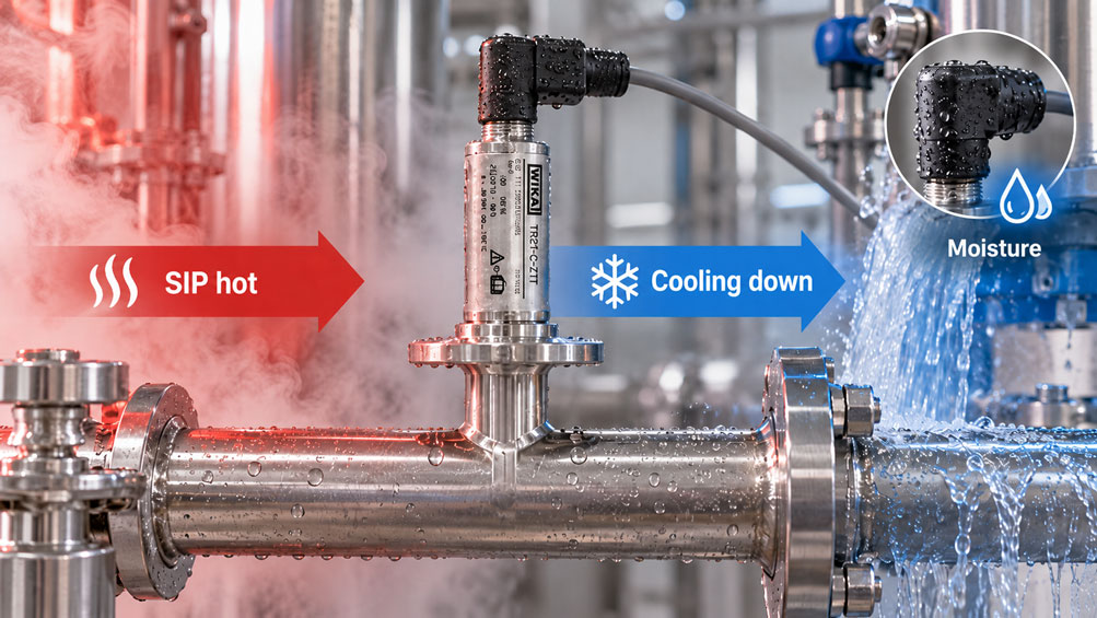
A temperature sensor operates completely normally for hours during production. After a CIP or SIP cycle, however, the control system suddenly shows an unstable value, an offset, a temporary sensor failure or an error message.
The obvious first suspicion is that the actual Pt100 sensing element is defective.
In hygienic systems, however, the cause is often more complex.
During Cleaning in Place and Sterilization in Place, the entire temperature measuring point is exposed to thermal and mechanical stress. Hot cleaning solution, pure steam, rinse water and subsequent cooling can cause large temperature changes within a short period of time.
Thermowell, sensor insert, process connection, seals, housing, connector, cable and, where applicable, the integrated transmitter all react differently to these temperature changes.
Moisture is another important factor.
If an electrical connection point is repeatedly exposed to hot water, steam or high-pressure cleaning over many cleaning cycles, damaged seals, unsuitable mating connectors or installation errors can create a path for moisture ingress.
After cooling, condensation can also form in areas that are not sufficiently protected against moisture.
The resulting fault pattern can therefore vary considerably: A sensor may fail directly during SIP, only during cooling, exclusively after the subsequent washdown, or apparently at random several hours later.
For this reason, abnormal temperature readings should not be investigated by checking only the resistance element.
The entire measurement chain must be considered: process connection, thermowell, sensor, electrical connection, cable, transmitter and PLC input.
It is equally important to distinguish between a permissible high process temperature and actual resistance to rapid temperature changes. A sensor specified for 150 or 250 °C, for example, is not automatically qualified for arbitrarily fast changes between hot and cold conditions.
The key point is: In recurring CIP and SIP processes, the reliability of a temperature measuring point is not determined solely by the maximum permissible temperature. The rate of temperature change, moisture protection, process connection, sensor construction, installation position and electrical connection version are also decisive.
Table of Contents
- What do CIP and SIP mean for a temperature sensor?
- Which parts of the measuring point are actually exposed to stress?
- Why can rapid temperature changes be critical?
- High temperature and thermal shock are not the same thing
- Why moisture is a common cause of failure
- How condensation can form in the connection area
- Consider M12 connectors and mating connectors as one complete connection
- What IP67 and IP69K actually mean
- Why the connection cable must also be suitable
- How a damaged Pt100 sensing element can become noticeable
- Consider 2-, 3- and 4-wire circuits during diagnostics
- Select the hygienic process connection correctly
- What role do thermowell and heat transfer play?
- Correctly evaluate insertion length and response time
- Consider the integrated transmitter as a possible source of error
- When is a calibration check useful after CIP/SIP?
- Distinguish gradual drift from sudden failure
- Systematically diagnose typical fault patterns
- Select temperature sensors for recurring CIP/SIP cycles
- Suitable temperature measurement technology from ICS Schneider
- Conclusion
- Frequently asked questions about temperature sensors after CIP and SIP
1. What do CIP and SIP mean for a temperature sensor?
CIP stands for Cleaning in Place.
The system is cleaned without removing pipelines, vessels and measuring instruments for each cleaning process.
Depending on the process, the components pass through different phases involving water, cleaning solutions, rinsing media and different temperatures.
SIP stands for Sterilization in Place or Steam in Place.
The already cleaned system is sterilized while remaining installed, frequently using condensing pure steam.
In pharmaceutical SIP applications, typical steam temperatures are approximately between 121 and 134 °C. The actual required temperature, pressure and holding conditions, however, depend on the validated process.
For a temperature sensor, this means that it must not only function during the production process.
It must also withstand the cleaning and sterilization phases permanently and subsequently continue to measure reproducibly.
The repeated sequence of different process conditions is precisely what makes hygienic measuring points demanding.
2. Which parts of the measuring point are actually exposed to stress?
To correctly diagnose a fault after CIP or SIP, the individual components of the measuring point must first be considered separately.
| Component | Typical stress | Possible consequence |
|---|---|---|
| Pt100/Pt1000 sensing element | Temperature and rapid temperature changes | Drift or failure if limits are exceeded |
| Thermowell / immersion stem | Temperature changes, flow and mechanical stress | Changed heat transfer or mechanical damage |
| Process connection | Steam, cleaning chemicals, seal stress | Leakage or hygienic weak point |
| Connector | Moisture, washdown and temperature | Contact problems, leakage currents or corrosion |
| Cable | Temperature, cleaning chemicals and mechanical movement | Embrittlement or insulation faults |
| Transmitter | Ambient temperature and moisture | Drift, error message or signal failure |
A temperature problem should therefore not automatically be equated with a defective sensing element.
Especially if the fault occurs only after cleaning or sterilization, connection points and moisture should be investigated just as carefully as the sensor itself.
3. Why can rapid temperature changes be critical?
During normal production, the temperature often changes comparatively slowly.
CIP and SIP can be different.
A hot cleaning solution may be followed immediately by a rinsing phase using significantly colder water.
After steam sterilization, the measuring point also cools down again.
This creates temperature gradients within the sensor.
The surface of a thin thermowell responds much more quickly than massive connection areas or the sensor housing.
Different materials and component geometries expand and contract at different rates during these changes.
The design of a sensor intended for such applications takes these stresses into account.
Nevertheless, the maximum permissible temperature should not be the only criterion when selecting a sensor.
If very rapid temperature changes are part of normal operation, the specified or proven thermal load capability for such changes is an independent selection criterion.
4. High temperature and thermal shock are not the same thing
A data sheet may specify a maximum process temperature of +150 °C or +250 °C, for example.
This value initially answers the question of which temperature the relevant device version may be exposed to under the specified conditions.
It does not automatically answer how quickly the temperature may change.
Slow heating from 20 to 130 °C represents a different thermal load from a change taking place within only a few seconds.
The fact that manufacturers consider these characteristics separately can be seen in specifically defined thermal-shock tests for hygienic temperature measuring instruments.
For particularly dynamic CIP/SIP applications, it should therefore be checked whether information on resistance to temperature changes or practical experience is available for the specific device.
A conclusion based solely on the maximum process temperature would not be technically sufficient.
5. Why moisture is a common cause of failure
In hygienic systems, the environment around a measuring point is regularly exposed to water, steam and, in some cases, high-pressure cleaning.
The electrical side of a temperature sensor must not be exposed to these conditions without suitable protection.
If moisture enters a connector or connection area, insulation resistance can decrease.
With a Pt100, even a comparatively small additional electrical influence can result in a measurable temperature deviation.
With more severe moisture ingress, unstable values, short circuits or open-circuit messages may occur.
Corrosion at the contacts can also cause a fault to appear only intermittently at first and then become permanent as operating time increases.
WIKA explicitly identifies moisture as a common cause of sensor failures and therefore equips hygienic temperature sensors with appropriately protected electrical components.
However, the specified degree of protection must apply to the actual selected device and connection version.
6. How condensation can form in the connection area
Not all moisture has to enter through direct water spray.
Strong temperature changes can also alter the conditions for condensation.
If a hot sensor is subsequently cooled rapidly, the temperature and relative humidity of the enclosed or surrounding air change.
If a connection area is not permanently sealed or sufficiently isolated from ambient moisture, condensation can form on colder surfaces.
A fault that does not occur during the hot SIP phase but only during or immediately after cooling is therefore particularly suspicious.
Another indication may be that the sensor temporarily operates normally again after a long dry standstill period.
Such an observation does not prove moisture ingress, but it makes inspection of the connector, seal, cable and insulation worthwhile.
7. Consider M12 connectors and mating connectors as one complete connection
Compact hygienic temperature sensors frequently use an M12 connector.
The connector allows the sensor to be replaced quickly and requires little installation space.
However, the protective effect is not provided by the M12 socket on the sensor alone.
The mating connector, seal and cable must also be suitable for the required degree of protection and environmental conditions.
A sensor version designed for IP69K does not automatically achieve the same resistance as a complete measuring point if an unsuitable mating connector is installed.
A connector that is only partially tightened can also impair the intended sealing effect.
If faults repeatedly occur after washdown, the complete connection should therefore be disconnected and checked for moisture, corrosion and mechanical damage.
8. What IP67 and IP69K actually mean
The degree of protection describes the protection of electrical components against the ingress of foreign objects and water under defined test conditions.
Depending on the version, hygienic WIKA resistance thermometers such as the TR21-B and TR21-C are available with moisture protection to IP67 or IP69K.
For frequent intensive external cleaning, the specific degree of protection is therefore an important selection criterion.
However, it must not be confused with process-temperature resistance.
A sensor may be very well protected against external water and still be unsuitable for a particular SIP temperature.
Conversely, a sensing element may tolerate high temperatures while the electrical connection version is not designed for intensive external cleaning.
Both requirements must be met separately.
9. Why the connection cable must also be suitable
The sensor housing is only one part of the electrical connection.
The connected cable is also cleaned, heated, cooled and potentially moved mechanically.
The cable jacket must therefore be sufficiently resistant to temperature, water and the cleaning chemicals used.
A cable that performs reliably for years in a dry control cabinet is not automatically suitable for a hygienic production environment.
Mechanical stress is particularly significant at bending points and directly behind the connector.
A damaged cable jacket can absorb moisture and carry electrical faults into the connection point.
During troubleshooting, the cable should therefore not only be tested for continuity but also visually inspected for crushing, kinks, cracks and discoloration.
10. How a damaged Pt100 sensing element can become noticeable
By definition, a Pt100 has a nominal resistance of 100 Ω at 0 °C.
As temperature increases, this resistance increases according to a defined characteristic curve.
A completely interrupted sensing element normally results in a clear error indication or a very high resistance value.
Other faults can be more subtle.
A changed connection resistance, an insulation problem or a partially damaged connection may initially cause only an offset or an intermittent fault.
The resistance should therefore not be measured only once at room temperature.
If the fault is temperature-dependent, a test during controlled heating and cooling can provide significantly more useful information.
The permissible test conditions of the sensor must of course be observed.
11. Consider 2-, 3- and 4-wire circuits during diagnostics
With a resistance thermometer, the connection cable forms part of the electrical measurement chain.
In a 2-wire circuit, the lead resistance directly influences the measured result.
A 3-wire circuit compensates for the lead resistance provided that the individual lead resistances are sufficiently similar.
A 4-wire circuit allows the sensor resistance to be separated even more effectively from lead resistance.
However, moisture or corrosion can cause faults that do not necessarily behave like a simple symmetrical lead resistance.
A 3- or 4-wire measurement therefore does not make a wet or damaged connector uncritical.
During diagnostics, the individual conductors should be checked against one another and, where appropriate, against the housing or earth.
12. Select the hygienic process connection correctly
CIP- and SIP-capable systems require process connections that can be completely cleaned or sterilized.
Dead spaces, gaps and areas with poor flow-through should be avoided.
Hygienic resistance thermometers are therefore available with Clamp, sterile threaded, welded and other aseptic connection types.
The WIKA TR21-C has an integrated sterile connection and is specifically designed for hygienic applications in food, beverages, pharmaceuticals and biotechnology.
The TR21-B is intended for orbital welding and has self-draining process areas with minimized dead space.
The selection of the process connection affects more than hygiene.
It also determines heat transfer, insertion length, mechanical loading and maintenance options.
13. What role do thermowell and heat transfer play?
The Pt100 does not measure the process temperature directly, but initially measures the temperature at its own installation point.
Depending on the design, the thermowell, sensor sheath and internal contact points lie between the process medium and the sensing element.
This creates a thermal time constant.
A massive thermowell responds more slowly to a temperature change than a compact thin-walled design.
A very robust design can therefore offer mechanical advantages while simultaneously increasing the response time.
This is particularly relevant for CIP and SIP if the temperature is not only monitored but also used to release a time-limited cleaning or sterilization step.
The measured temperature profile must then reproduce the actual process quickly and reproducibly enough.
14. Correctly evaluate insertion length and response time
A temperature sensor with insufficient insertion depth can be more strongly influenced by the pipe wall or ambient conditions.
For small pipe diameters, however, an arbitrarily large insertion length is not possible either.
In addition, a long, slender immersion stem increases the mechanical load caused by flow.
Pipe diameter, insertion length, flow velocity, sensor design and required response time must therefore be considered together.
High flow velocities can occur particularly during CIP.
For very short response times, an inline solution can be useful in which no conventional long thermowell protrudes deeply into the process.
The exact design should nevertheless be derived from the process and hygienic concept.
15. Consider the integrated transmitter as a possible source of error
Many hygienic temperature sensors can be supplied either with a direct Pt100/Pt1000 output or with an integrated 4–20 mA transmitter.
With a transmitter, the small resistance signal is converted directly at the sensor into a robust current signal.
This offers numerous advantages for longer cable runs and integration into the control system.
However, another electronic component must then be considered during troubleshooting.
If a 4–20 mA signal indicates an incorrect value after SIP, the sensing element, transmitter or electrical connection may be responsible.
Depending on the device version, a comparison between the internal sensor value and the output signal can therefore be helpful.
The permissible ambient temperature of the transmitter must also be observed.
The process side can be significantly hotter than the electronics side is permitted to become.
16. When is a calibration check useful after CIP/SIP?
A temperature sensor does not have to be recalibrated after every CIP cycle.
However, a defined inspection strategy is useful in validated or quality-critical processes.
Persistent offset changes, increasing drift or differences between two redundant measuring points are particularly suspicious.
The measurement chain should also be checked after repairs, mechanical damage or moisture ingress.
A calibration can show whether the measurement deviation is reproducible.
However, it does not replace fault analysis.
A connector that fails only intermittently under high humidity may appear completely normal during a dry laboratory calibration.
Where possible, the observed fault should therefore be reproduced under controlled conditions.
17. Distinguish gradual drift from sudden failure
The way a fault develops often provides important clues.
A sudden jump immediately after a washdown process indicates a connection, moisture or contact problem more strongly than gradual sensor ageing.
A deviation that increases over several months may instead indicate drift or repeated thermal loading.
A fault that occurs exclusively during the hot phase points toward a temperature-dependent component.
A fault that occurs only during cooling can make moisture or temperature-dependent contact problems more likely.
| Fault pattern | Possible cause | Recommended check |
|---|---|---|
| Failure immediately after washdown | Moisture in connector or cable | Check electrical connection and insulation |
| Fault only at high temperature | Temperature-dependent sensor, cable or electronics fault | Heat the measurement chain under controlled conditions |
| Fault appears only during cooling | Condensation or temperature-dependent contact fault | Observe cooling phase and insulation resistance |
| Measured value permanently shifted | Calibration drift or permanent damage | Perform comparative calibration |
| Irregular jumps | Contact problem or cable break | Mechanically check connector and cable |
| Slow response after modification | Changed insertion length or heat transfer | Compare mechanical configuration |
18. Systematically diagnose typical fault patterns
| Observation | Possible cause | Recommended check |
|---|---|---|
| Sensor works before CIP but not afterwards | Moisture or damaged connector | Open connector, dry it and check insulation |
| Pt100 value jumps when the cable is moved | Cable break or contact problem | Check cable and connector section by section |
| Measured value changes slightly and permanently after every SIP sterilization | Drift or thermal loading | Compare calibration history |
| Sensor measures correctly, but 4–20 mA output is wrong | Transmitter or configuration | Check sensor resistance and output signal separately |
| Fault occurs only during steam phase | Temperature limit or thermal fault | Check device version and permissible temperatures |
| Fault occurs after cold final rinse | Rapid temperature change or moisture | Investigate temperature profile and connection area |
| Display responds significantly more slowly after sensor replacement | Different insertion length or thermowell geometry | Compare mechanical design |
| Several sensors fail in the same plant area | Process or washdown condition rather than an individual fault | Check temperature, cleaning and installation conditions together |
19. Select temperature sensors for recurring CIP/SIP cycles
Selection begins with the actual temperature profile.
Not only the maximum product temperature, but also the CIP and SIP temperatures must be known.
It should also be clarified how quickly the system is heated and cooled.
The next considerations are the process connection and hygienic design.
Product-contacting areas should be easy to clean, have little or no dead space and be suitable for the media used.
The electrical side is assessed separately.
Here, degree of protection, connector, mating connector, cable material and ambient temperature are decisive.
For the metrological function, insertion length, response time, sensor type, accuracy class and, where applicable, the transmitter must be considered.
A suitable design therefore does not begin with the question “Which Pt100 measures up to 150 °C?”, but with the complete process description.
20. Suitable temperature measurement technology from ICS Schneider
ICS Schneider Messtechnik offers resistance thermometers, thermowells, transmitters and other temperature measurement technology for hygienic processes, food production, pharmaceuticals and biotechnology. An overview can be found under Temperature Measurement Technology and Resistance Thermometers / Pt100 Sensors.
20.1 WIKA TR21-C for Compact Hygienic Measuring Points
The WIKA TR21-C is a compact miniature resistance thermometer for sterile and hygienic process applications.
It is designed for liquid and gaseous media in the range from -30 … +250 °C.
Pt100 or Pt1000 versions in 3- or 4-wire configuration are available, as are versions with an integrated 4–20 mA transmitter.
The electrical connection is made via M12 x 1.
Depending on the version, the electrical components are protected against moisture to IP67 or IP69K.
The process connections are designed in terms of material and geometry for hygienic measuring points.
A specially temperature-resistant version is also available for applications in which the sensor must be sterilized in an autoclave.
20.2 WIKA TR21-B for Orbitally Welded Hygienic Piping
The WIKA TR21-B is designed for sterile process applications and orbital welding.
The wetted parts are made of stainless steel 1.4435.
The design is self-draining and minimizes dead space.
The TR21-B is also available with a direct Pt100/Pt1000 output or with an integrated 4–20 mA transmitter.
An integrated spring mechanism ensures contact between the sensor tip and the bottom of the thermowell, supporting a short response time and reproducible heat transfer.
This makes the design particularly interesting when hygiene, process integration and response speed must be considered together.
20.3 WIKA TR25 for Inline Measurements
The WIKA TR25 is an inline resistance thermometer for pipelines with demanding hygienic requirements.
The design has transitions without dead spaces and is expressly suitable for CIP and SIP processes.
Because no conventional thermowell needs to extend deeply into the product flow, the design is particularly suitable for piggable pipelines, highly viscous media and flows with high shear forces.
Pt100 sensing elements in accuracy classes A or B according to IEC 60751 are used.
ICS particularly highlights the combination of high measuring accuracy and short response time for this series.
20.4 Which design is suitable?
A compact TR21-C can be a suitable solution for many standard hygienic measuring points.
The TR21-B offers advantages in orbitally welded and self-draining piping systems.
The TR25 becomes particularly interesting when an inline measurement without a conventional immersion thermowell is required.
However, the decisive factor is always the specific CIP/SIP profile, including maximum temperature, temperature changes, cleaning chemicals, pressure, flow and external washdown conditions.
21. Conclusion
A temperature sensor can withstand the maximum SIP temperature without any problem and still fail after repeated cleaning cycles.
The reason is that CIP and SIP stress the entire measuring point, not only the Pt100 sensing element itself.
Rapid changes between hot cleaning medium, pure steam and cold rinse water create thermal stress in the thermowell, sensor, connection and housing.
The maximum permissible temperature alone does not fully describe this dynamic loading.
At the same time, moisture is an important potential source of failure.
Connectors, mating connectors, cables and seals must therefore be just as well suited to the application as the temperature sensor itself.
The timing of the fault is particularly informative.
If it occurs directly after washdown, the electrical connection is suspect. If it occurs only at high temperature, the temperature resistance of the measurement chain must be assessed. If the fault begins only during cooling, condensation or moisture should also be investigated.
A good diagnostic procedure also separates the sensing element, wiring path and transmitter.
For reliable design, the following sequence therefore applies:
Determine product, CIP and SIP temperatures → consider the rate of temperature change → select a hygienic process connection → design insertion length and heat transfer → determine moisture protection of the electrical connection → select a suitable mating connector and cable material → check the transmitter’s permissible ambient temperature → observe the actual measuring point after CIP/SIP → document the calibration trend → diagnose faults systematically according to the process phase in which they occur.
The most important practical principle is therefore: A temperature sensor suitable for CIP/SIP must not only be capable of reaching high temperatures. As a complete functioning measurement chain, it must also withstand repeated temperature changes, moisture and the complete hygienic cleaning environment over the long term.
22. Frequently asked questions about temperature sensors after CIP and SIP
22.1 What does CIP mean for a temperature sensor?
CIP stands for Cleaning in Place. The sensor remains installed during cleaning and is exposed together with the pipeline or vessel to cleaning media, temperature and flow.
22.2 What does SIP mean?
SIP stands for Sterilization in Place or Steam in Place. The system is sterilized while installed, frequently using condensing pure steam.
22.3 What temperatures typically occur during SIP?
In conventional pharmaceutical pure-steam processes, typical temperatures are approximately between 121 and 134 °C. However, the actual validated SIP process is always decisive.
22.4 Why can rapid temperature changes be problematic?
Different components of the sensor heat up and cool down at different rates. This creates thermal gradients and mechanical stress.
22.5 Does a maximum sensor temperature of 250 °C automatically mean high thermal-shock resistance?
No. Maximum process temperature and the permissible or tested rate of temperature change are different properties.
22.6 Can moisture distort a Pt100 reading?
Yes. Moisture in connectors or cables can alter electrical insulation and contact conditions and thereby cause offsets, unstable values or failures.
22.7 Why does a fault sometimes occur only during cooling?
During cooling, the temperature and moisture conditions at the measuring point change. With an insufficiently protected connection, condensation or a moisture-dependent contact fault may then become visible.
22.8 Is IP67 sufficient for CIP/SIP?
This depends on the external cleaning load. The degree of protection of the actual version and complete connector system must suit the real washdown conditions.
22.9 What does IP69K provide?
IP69K describes increased protection against intensive high-pressure/high-temperature water exposure according to the underlying test. However, it does not replace assessment of process or chemical resistance.
22.10 Does the M12 mating connector also have to be suitable?
Yes. The complete connection consisting of sensor connection, mating connector, seal and cable must achieve the required protective performance.
22.11 Can the cable itself cause a failure?
Yes. Cracks, kinks, unsuitable cable materials or damaged transitions can cause moisture ingress and electrical faults.
22.12 How can I check whether the Pt100 itself is actually defective?
The sensor resistance should be checked separately from the rest of the signal path and compared with the corresponding temperature. For intermittent faults, a controlled test over the relevant temperature range may also be necessary.
22.13 Does a 4-wire circuit help with moisture problems?
It reduces the influence of normal lead resistance, but it does not automatically make a wet or corroded connector uncritical.
22.14 Should a temperature sensor be calibrated after every SIP cycle?
Not generally. The inspection interval is derived from process criticality, quality requirements, practical experience and, where applicable, regulatory requirements.
22.15 Why is insertion length important?
It influences heat transfer, response time, heat conduction to the surroundings and the mechanical loading of the immersion stem.
22.16 When is an inline temperature sensor useful?
When a conventional thermowell extending into the process is undesirable, for example in piggable pipelines, highly viscous media or certain hygienic applications.
22.17 Is the WIKA TR21-C suitable for hygienic processes?
Yes. The TR21-C was developed for sterile process applications, features hygienic process connections and is available with moisture protection to IP67 or IP69K depending on the version.
22.18 Is the WIKA TR25 suitable for CIP and SIP?
Yes. ICS and WIKA explicitly describe the TR25 as suitable for CIP and SIP and designed for hygienic pipeline applications.
22.19 What information does ICS Schneider require when investigating a sensor problem after SIP?
Useful information includes the sensor type, process connection, electrical connection version, product and SIP temperatures, temperature profile, cleaning media, washdown conditions, time at which the fault occurs, and whether the sensor is evaluated directly as Pt100/Pt1000 or via a transmitter.
22.20 What information does ICS Schneider require for a new design?
Required information includes the normal process range, CIP and SIP temperatures, rate of temperature change, medium and cleaning chemicals, pressure, flow, pipe diameter, insertion length, hygienic process connection, required accuracy and response time, electrical connection, degree of protection and desired output signal.