


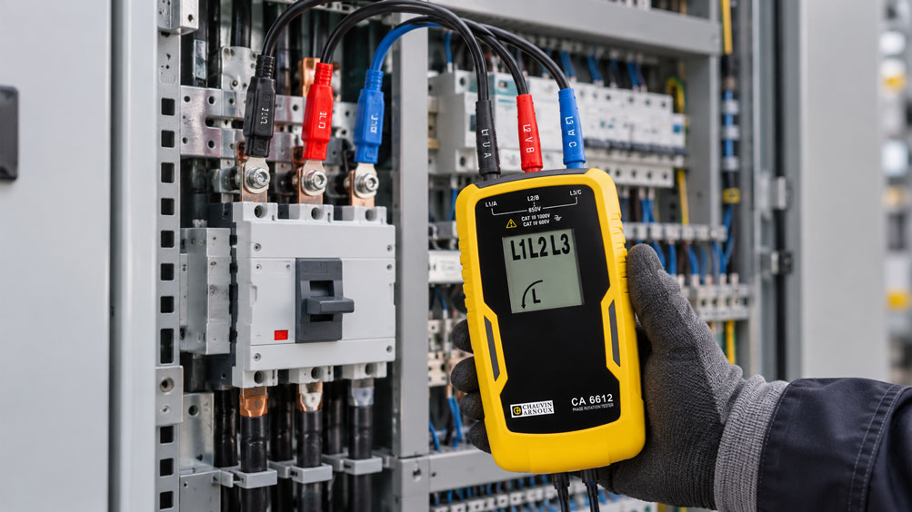
A new standby power supply is being commissioned at an industrial production facility. If the public power grid fails, a three-phase generator takes over the supply of selected loads. In addition, an uninterruptible power supply (UPS) protects sensitive control systems and IT equipment. During the first changeover test, it becomes apparent that a pump connected directly to the three-phase supply rotates in the wrong direction after switching to generator power. At the same time, the UPS reports a phase sequence fault at its bypass input.
At first glance, both voltage sources appear to be operating normally. The measured line-to-line voltages are within the specified range, and the frequencies also appear plausible. Nevertheless, the assignment of the phase conductors may differ. Swapping just two phase conductors reverses the phase rotation. With a directly connected three-phase motor, this can reverse the direction of rotation.
The test becomes more demanding when two power sources are intended to operate not only alternately but also briefly in parallel. Identical clockwise phase rotation does not automatically mean that both voltage sources are in phase or synchronized. For a permissible parallel connection, the voltage magnitudes, frequencies and instantaneous phase angles must also remain within the synchronization limits defined for the installation.
It is therefore particularly important to distinguish between an interlocked power supply changeover with an interruption and a synchronized transition involving a brief overlap. During a changeover with an interruption, the power sources are not electrically connected to one another. During an overlapping changeover or parallel operation with the grid, suitable synchronization and protection functions must be provided.
This technical article explains how to correctly test and evaluate phase rotation, phase conductor assignment and synchronization after modifications to power supply changeover systems. It focuses on generators, UPS systems, standby power installations, transfer switching equipment and suitable measuring instruments. A calculation example demonstrates why two sources with identical phase rotation and nearly equal frequencies are nevertheless not continuously in phase. The article also covers test parameters, electrical safety, typical fault patterns, commissioning and suitable testing instruments from the ICS product range.
Table of Contents
- Clearly Define the Power Supply Changeover and Electrical Testing Task
- Understand Phase Rotation in a Three-Phase AC System
- Distinguish Phase Rotation, Phase Conductor Assignment and Phase Alignment
- Evaluate the Effects of Incorrect Phase Sequence on Three-Phase Motors
- Consider the Grid, Generator, UPS and Standby Power System as Different Sources
- Distinguish Open-Transition and Synchronized Transfer Switching
- Define the Required Electrical Test Parameters
- Compare Voltage, Frequency and Phase Angle Between Two Power Sources
- Calculation Example: How the Phase Angle Changes at 50.0 and 49.8 Hz
- Correctly Evaluate the Phase Rotation of a Generator Supply
- Check UPS Input, Inverter Output and Bypass Separately
- Consider Neutral Conductors, Protective Conductors and Earthing Systems During Changeover
- Verify the Direction of Rotation of Connected Loads After Changeover
- Select Suitable Phase Rotation Testers and Voltage Testers
- Safely Distinguish Voltage Testing from Phase Rotation Testing
- Distinguish Synchroscopes, Synchronization Checks and Parallel-Connection Authorization
- Evaluate Transfer Interlocking, Backfeeding and Switching States
- Record Voltage Dips, Frequency Changes and Transient Transfer Events
- Evaluate Instrument Accuracy, Testing Safety and Documentation
- Perform a Systematic Testing and Commissioning Procedure
- Diagnose Typical Fault Patterns After a Power Supply Changeover
- Suitable Phase Rotation Testers and Synchronization Instruments from ICS Schneider
- Conclusion: Identical Phase Rotation Is Necessary but Not Always Sufficient
- Frequently Asked Questions About Phase Rotation Testing for Generators and UPS Systems
1. Clearly Define the Power Supply Changeover and Electrical Testing Task
Before carrying out a phase rotation test, it is necessary to establish which power supply installation is being examined and how it is intended to operate during a changeover.
A typical low-voltage installation may have a public grid supply and an additional supply from a generator.
Transfer switching equipment selects which voltage source supplies the connected loads.
Other installations may also include UPS systems, inverters, battery storage systems or additional generators.
The electrical requirements differ depending on the circuit concept.
In a simple interlocked standby power system, the existing supply is disconnected first. Only then is the alternative supply connected.
With such break-before-make transfers, synchronization of two simultaneously connected voltage sources is normally not required.
Nevertheless, phase rotation, correct phase conductor assignment, earthing arrangement and permissible supply conditions must be checked.
The situation is different when parallel operation with the grid is intended.
In this case, two active voltage sources may be electrically connected to one another.
Additional suitable synchronization functions, protective devices and appropriately designed switching equipment are required.
It is particularly important to clearly define whether a supply interruption is permissible during the changeover or must explicitly be avoided.
The type of connected load must also be considered.
For example, induction motors connected directly to a three-phase supply respond differently to changes in phase sequence than many devices with an upstream rectifier.
A complete testing task therefore requires information about the installation structure, power sources, transfer method, earthing arrangement, protection concept and relevant loads.
2. Understand Phase Rotation in a Three-Phase AC System
A balanced three-phase system consists of three sinusoidal AC voltages that are ideally displaced by 120 electrical degrees relative to one another.
The three phase conductors are usually designated L1, L2 and L3.
The temporal sequence of their voltage waveforms determines the direction of phase rotation.
For the correspondingly defined phase sequence L1 – L2 – L3, this is referred to as clockwise phase rotation.
If the sequence is changed by swapping two phase conductors, counterclockwise phase rotation results.
The exact clockwise or counterclockwise indication refers to the connection sequence and reference direction of the phase rotation tester being used.
A phase rotation tester detects the temporal sequence of the three phase voltages.
Depending on its design, it uses three electrical test connections or another expressly specified measurement method.
A suitable instrument indicates clockwise or counterclockwise phase rotation using symbols, arrows or LEDs, for example.
However, the phase sequence alone provides no information about the instantaneous phase angle of a second independent voltage source.
It initially describes only the temporal sequence within the three-phase system being tested.
Likewise, a line-to-line voltage of 400 V, for example, does not indicate whether two different power sources are synchronized.
A complete assessment therefore requires several electrical characteristics to be checked separately.
3. Distinguish Phase Rotation, Phase Conductor Assignment and Phase Alignment
In connection with generators and power supply changeovers, the terms phase rotation, phase sequence and phase alignment are often used imprecisely.
Technically, however, they describe different characteristics.
Phase rotation describes the temporal sequence of the three phase voltages.
Phase conductor assignment determines which conductor or phase path of a power source is assigned to the corresponding connection within the installation.
The instantaneous phase angle describes the angular difference between the voltage waveforms of two sources being compared.
One particularly important distinction is that two three-phase systems may both have clockwise phase rotation even though their individual phase conductors are not assigned identically.
A cyclic permutation of L1, L2 and L3 preserves the direction of phase rotation.
A simple phase rotation tester may therefore show the same clockwise indication for both power sources.
Nevertheless, the actual assignment of L1, L2 and L3 may differ between the two supplies.
An identical phase rotation indication alone therefore cannot establish that individual phase conductors have the same phase angle.
With independent generators, the phase angle may also change continuously over time.
Even if the nominal voltages are identical and both sources have clockwise phase rotation, their sinusoidal voltages may be shifted relative to one another in time.
The following distinction is therefore essential:
Identical phase rotation means the same phase sequence – not necessarily identical phase conductor assignment and not necessarily synchronization.
For an electrical parallel connection, the specified synchronization conditions must also be verified.
4. Evaluate the Effects of Incorrect Phase Sequence on Three-Phase Motors
Phase sequence is directly relevant to motors connected to a three-phase supply.
In a typical three-phase induction motor, the direction of the electromagnetic rotating field determines the direction of rotor rotation.
If the phase sequence is reversed, the mechanical direction of rotation of the motor may also reverse.
This is relevant for pumps, fans, conveyor systems and other rotating machinery, for example.
A pump rotating in the wrong direction after a changeover may be unable to achieve the required flow rate.
In certain machines, additional mechanical or process-related hazards may arise.
However, not all electrical drives respond in the same way to a changed input phase sequence.
With many variable frequency drives, the incoming AC voltage is first rectified and then converted back into AC by an inverter stage.
The direction of rotation of the connected motor can then be specified by the drive independently of the phase sequence of the incoming supply.
This distinction is particularly important in installations with a variable frequency drive bypass.
The motor may rotate correctly during inverter operation but in the opposite direction when operating directly through the mains bypass.
Commissioning must therefore consider the actual supply paths and operating modes.
Phase rotation testing is consequently an important prerequisite for checking motor rotation, but it does not replace every necessary functional test of the machine.
5. Consider the Grid, Generator, UPS and Standby Power System as Different Sources
Industrial power supply systems may contain several electrically different sources.
The public grid normally provides voltage and frequency within defined operating conditions.
A standby generator, on the other hand, produces its own AC voltage, with frequency depending on the drive system and generator control.
A UPS system may supply its output voltage through an inverter.
Depending on the operating mode and design, the UPS output may be synchronized with a bypass source or initially operate independently of it.
A standby power installation may also have several different operating states.
Typical states include normal grid supply, generator starting, standby power operation, transfer back to the grid and, where applicable, planned synchronized operation.
Electrical testing must distinguish between these conditions.
For example, checking phase rotation at the grid input does not automatically establish the phase sequence at the output of a three-phase UPS.
Likewise, measurement directly at the generator does not confirm that the phase conductors have been assigned correctly at a remote transfer switch.
Additional switching devices, transformers and cables may be installed between the generator and the loads.
Depending on the arrangement, these can affect phase conductor assignment or phase angle.
Reliable commissioning therefore requires the actual electrical conditions to be evaluated at the relevant measuring points and connection interfaces.
6. Distinguish Open-Transition and Synchronized Transfer Switching
A fundamental difference between transfer switching systems is how the two power sources behave during the transfer process.
With an open-transition transfer, the existing power source is disconnected before the new source is connected.
This method is known as Open Transition or Break-Before-Make.
The two supplies are not intended to be connected simultaneously.
With an overlapping transfer, both sources may be connected to the load simultaneously for a defined period.
This method is known as Closed Transition or Make-Before-Break.
If this results in two active sources being electrically connected in parallel, suitable synchronization and protection conditions must be fulfilled.
| Operating Mode | Electrical Behaviour | Important Tests | Special Consideration |
|---|---|---|---|
| Open Transition | Existing supply is disconnected before the new source is connected | Phase rotation, phase conductor assignment, voltages, interlocking and protective functions | No intended parallel connection of the two sources |
| Closed Transition | Planned brief overlap of the two power sources | Additional synchronization conditions, switching authorizations and protection concept | Only with suitable and approved transfer switching equipment |
| Generator-grid parallel operation | Generator and grid are electrically connected simultaneously | Voltage, frequency, phase angle, synchronization checking and grid protection | Grid connection and protection requirements must be fulfilled |
| UPS with static bypass | Load is supplied through the inverter or bypass depending on operating conditions | Phase sequence, voltage and frequency limits, and manufacturer-specific synchronization conditions | Internal UPS transfer logic and equipment approvals are decisive |
| UPS maintenance bypass | Load can be supplied through a separate maintenance path | Specified switching sequence, phase assignment, neutral conductor concept and interlocking | Only according to the specific manufacturer and installation procedure |
The table demonstrates why the statement “both sources have clockwise phase rotation” is insufficient for complete transfer authorization.
With open-transition switching, correct conductor assignment and reliable separation of the power sources are particularly important.
For planned parallel operation, synchronization conditions must additionally be monitored reliably.
The IEC 60947-6-1 standard is among the relevant standards for corresponding transfer switching equipment.
Actual suitability depends on the transfer switching equipment used, its configuration and the overall installation design.
7. Define the Required Electrical Test Parameters
Reliable testing after a power supply changeover must cover the electrical quantities relevant to the installation.
Phase rotation is only one part of this assessment.
Line-to-line voltages and, where applicable, phase-to-neutral voltages are also relevant.
With a three-phase low-voltage supply, voltage balance must also be considered.
If a phase conductor is missing or significant voltage unbalance occurs, a three-phase load may operate under impermissible conditions.
The frequency must also be suitable for the intended supply and connected loads.
With a generator supply, frequency may behave differently during load changes than with the public grid.
For intended parallel operation, the instantaneous phase angles between the corresponding phase conductors must also be considered.
The required synchronization limits depend on the specific installation and the protective or synchronization functions used.
They must not be replaced with arbitrary general values.
Power quality may also be relevant.
For sensitive loads, voltage dips, brief interruptions and frequency deviations during transfer may be decisive.
Complete testing therefore often requires different measuring instruments.
A simple phase rotation tester is suitable for determining phase sequence, while a power quality analyzer can record additional electrical quantities and events.
A measuring system designed for synchronization serves another function again.
8. Compare Voltage, Frequency and Phase Angle Between Two Power Sources
When two active AC voltage sources are intended to operate in parallel, their electrical conditions must be sufficiently matched.
The essential quantities are voltage magnitude, frequency and phase angle.
In three-phase systems, correct phase sequence and phase conductor assignment must also be ensured.
Differences in voltage magnitude can cause substantial circulating currents when the sources are connected.
Different frequencies cause the relative phase angle of the sources to change continuously.
An existing phase angle difference can also cause high electrical and mechanical stresses during connection.
Actual generator synchronization therefore requires appropriate control and monitoring functions.
With a synchronous generator, excitation and prime mover control can be used, for example, to match electrical conditions to those of the supply to which the generator is to be connected.
A synchronization device then monitors the relevant quantities and permits switching within the specified limits.
These limits depend on the installation, generator, switching device and protection concept.
A conventional phase rotation tester does not fully measure these synchronization conditions.
A digital multimeter with frequency measurement is also not, by itself, a suitable replacement for a dedicated synchronization check.
It is particularly important to consider the closing time of the circuit breaker used.
The phase angle may continue to change during the actual switching movement.
The synchronization controller must therefore operate according to the intended installation concept and specified switching equipment characteristics.
9. Calculation Example: How the Phase Angle Changes at 50.0 and 49.8 Hz
A simplified example considers two independent three-phase AC voltage sources.
Source A is the public grid with a frequency of 50.0 Hz.
Source B is a generator with a frequency of 49.8 Hz.
Both sources provide idealised sinusoidal voltages with a nominal line-to-line voltage of 400 V.
The direction of phase rotation is also identical for both sources.
At the beginning of the analysis, the compared voltages are assumed to have the same instantaneous phase angle.
The frequency difference is:
Δf = fA − fB
Δf = 50.0 Hz − 49.8 Hz = 0.2 Hz
With a constant frequency difference, the relative phase angle changes over time.
For the idealised model:
Δφ(t) = 360° · Δf · t
With a frequency difference of 0.2 Hz, the rate of angular change is:
360° · 0.2 Hz = 72° per second
The following table shows how the phase angle develops.
| Time Since Assumed Phase Alignment | Accumulated Phase Angle Difference | Assessment |
|---|---|---|
| 0 s | 0° | Instantaneously aligned phase angles |
| 0.5 s | 36° | Already a significant phase displacement |
| 1.0 s | 72° | Phase displacement continues to increase |
| 2.5 s | 180° | Compared fundamental voltage waveforms are in opposition |
| 5.0 s | 360° | Instantaneously aligned again modulo 360°, but frequencies still differ |
After five seconds, the calculated relative phase angle has completed one full revolution.
The voltage waveforms may therefore briefly appear to be aligned again.
However, the sources still do not have the same frequency.
A temporarily small phase angle difference must therefore not be confused with continuously synchronized operation.
Even a relatively small frequency deviation can cause the phase angle to change rapidly.
The period duration is also important for a further assessment.
At 50 Hz, one complete electrical period lasts:
T = 1 / 50 Hz = 20 ms
A time displacement of 1 ms corresponds to the following phase angle for a 50 Hz fundamental waveform:
φ = 360° · 1 ms / 20 ms = 18°
This example demonstrates why even short timing differences between two voltage waveforms can result in a significant phase angle difference.
The figures describe only the physical relationship between frequency difference, time and phase angle.
They are not permissible limit values for synchronization or circuit breaker closing.
Such authorization conditions must be derived from the specific installation and protection system.
10. Correctly Evaluate the Phase Rotation of a Generator Supply
With a three-phase generator supply, it must be verified that the generated phase sequence is suitable for the intended installation.
Incorrect phase conductor assignment may occur particularly after initial installation, wiring modifications or component replacement.
Even if a generator is correctly wired internally, the assignment at a remote transfer switch may be different.
The intended interface or point of connection is therefore important for the assessment.
Testing must be performed under the permissible operating conditions defined in the test plan.
A suitable phase rotation tester can determine the phase sequence of the generator.
Voltage magnitude and frequency must also remain within the limits specified for the installation.
Electrical loading can affect generator behaviour.
Short-term frequency and voltage changes may occur particularly during load changes.
Measurements without load do not therefore automatically describe all conditions that will occur during subsequent standby power operation.
If the generator operates exclusively through a fully interlocked open-transition transfer switch, the correct supply of the connected loads is the main consideration.
If synchronized parallel operation with the grid is intended, the corresponding synchronization and grid protection functions must also be provided.
Phase rotation testing alone cannot authorize generator parallel connection.
Particularly in installations with multiple generators, the intended load sharing after synchronization must also be considered.
11. Check UPS Input, Inverter Output and Bypass Separately
A three-phase UPS installation may have different electrical operating paths.
These include the mains input, inverter output and, where applicable, a static or manual bypass.
Depending on the design, multiple mains inputs may be provided.
Correct phase sequence is particularly important in installations with separate rectifier and bypass inputs.
Manufacturers of modern UPS systems therefore frequently monitor phase sequence and various electrical operating limits.
Schneider Electric, for example, documents fault indications for incorrect phase sequence at the input or bypass.
A deviation between the inverter output and bypass source may also trigger an alarm or restrict permissible transfer operation.
A normal voltage indication at the UPS input therefore does not automatically confirm that the bypass is correctly connected.
It is particularly important to note that the inverter output of a UPS does not necessarily have the same phase sequence as every arbitrary upstream source.
The specific UPS topology and its control functions are decisive.
Appropriate testing must therefore distinguish between the electrical operating states specified by the manufacturer.
The maintenance bypass also requires separate consideration.
The electrical paths may differ from those used during normal UPS operation.
Transfer to such an operating state must only be performed according to the designated manufacturer and installation procedure.
The manufacturer’s requirements concerning phase sequence, neutral conductor routing, synchronization and the positions of the switching devices involved are particularly important.
12. Consider Neutral Conductors, Protective Conductors and Earthing Systems During Changeover
Safe design of a power supply changeover involves more than the three phase conductors.
Neutral conductors, protective conductors and the existing earthing system must also be considered.
Particularly with generator supplies, it may be necessary to determine whether the neutral conductor must be switched and how the star point or earthing arrangement is configured.
The permissible design depends, among other factors, on the earthing system and the actual installation structure.
For example, an installation may have different neutral conductor and earthing conditions for normal grid supply and standby power operation.
UPS systems may also have manufacturer-specific requirements concerning neutral conductor routing.
The selection of a three-pole or four-pole transfer switch must therefore not be based solely on the number of phase conductors present.
Avoiding impermissible neutral conductor paths or return current paths is particularly important.
Such faults can impair protective measures or cause undesirable currents to flow through other parts of the installation.
The correct functioning of installed residual current devices must also be considered.
A correctly indicated phase rotation provides no information about whether neutral conductor routing and the earthing concept have been designed correctly.
The protective conductor must not be treated as an active conductor that can be switched arbitrarily.
Suitable design must take the applicable installation standards, specific installation concept and manufacturer documentation into account.
Verification of the neutral conductor and protection concept is therefore a separate task alongside phase rotation testing.
13. Verify the Direction of Rotation of Connected Loads After Changeover
After modifying the power supply, functional testing of the connected loads may be necessary.
The intended direction of rotation is particularly important for motors connected directly to the three-phase supply.
An incorrect phase sequence can cause pumps, fans or conveyor systems to rotate in the opposite direction, for example.
A phase rotation tester can help detect a supply wiring error before the actual functional test.
However, electrical phase rotation testing does not replace verification of mechanical rotation in every case.
Some drives have additional electrical components between the supply and the motor.
These may include variable frequency drives, soft starters, transformers or switching devices.
Different operating paths may be particularly relevant in systems with an inverter bypass.
The motor may rotate correctly in one operating mode and incorrectly in another.
Commissioning must therefore consider all intended operating modes.
Functional testing must not create hazards for personnel, machinery or the process.
For sensitive installations, safe test conditions and suitable organisational measures may need to be established.
The direction of rotation must not be checked through an uncontrolled trial run if incorrect rotation could already cause damage.
The exact procedure forms part of the approved commissioning process.
14. Select Suitable Phase Rotation Testers and Voltage Testers
Different measuring instruments are available for checking phase sequence.
A conventional phase rotation tester is specifically designed to determine the temporal sequence of the phase conductors.
One example is the Chauvin Arnoux CA 6612.
This instrument indicates the phase sequence and the presence of the phase conductors.
The CA 6611 additionally offers functions for determining motor rotation direction.
Certain two-pole voltage testers also provide a phase rotation function.
Examples from the ICS product range include the BENNING DUSPOL digital and Chauvin Arnoux C.A 773.
These instruments combine voltage testing with additional functions, including suitable phase rotation testing.
The permissible voltage, frequency range and measurement category must be considered during selection.
The measurement category describes, among other things, suitability for certain transient electrical stresses.
The actual position of the measuring point within the electrical installation is also relevant.
Testing in low-voltage distribution boards may involve different requirements from testing at a simple downstream load connection.
The test leads and probes must also be suitable for the relevant conditions.
However, a phase rotation tester is not automatically suitable for comparing two independent, simultaneously energized power supply systems.
Such tasks require comparison or synchronization measuring instruments expressly specified for that purpose.
15. Safely Distinguish Voltage Testing from Phase Rotation Testing
An electrical installation may require different tests performed using different measurement functions.
Voltage testing is used, for example, to detect the presence of voltage or to verify the absence of voltage as part of the specified procedure.
Phase rotation testing, on the other hand, determines the temporal sequence of the phase conductors in a suitable energized three-phase system.
These tests are not identical.
Using suitable testing instruments is particularly important.
For verifying the absence of voltage in low-voltage installations, appropriately suitable two-pole voltage testers that meet the applicable requirements are used.
A simple phase rotation tester does not automatically replace such a test.
A single-pole voltage indication is also not sufficient on its own to prove the absence of voltage.
The applicable safety rules must be observed when working on electrical installations.
The DKE describes the five safety rules in accordance with DIN VDE 0105-100: Disconnect completely, secure against reconnection, verify the absence of voltage, carry out earthing and short-circuiting, and provide protection against adjacent live parts.
Their application depends on the specific working procedure and applicable requirements.
With standby power systems, particular attention must be paid to the fact that other energy sources may continue supplying voltage even when the public grid supply is switched off.
A UPS, for example, can continue operating from its stored energy.
Generators or other power sources can likewise keep an installation energized.
Testing and any necessary isolation must therefore account for all relevant energy sources.
Work and measurements may only be carried out by suitably qualified personnel according to a procedure approved for the installation.
16. Distinguish Synchroscopes, Synchronization Checks and Parallel-Connection Authorization
In installations designed for parallel operation, the electrical conditions of the power sources involved must be monitored appropriately.
One important quantity is the phase angle difference between the voltages being compared.
A synchroscope is used to indicate the relative synchronization state of two suitable voltage sources.
Depending on its design, it can indicate the direction and speed of a changing relative phase angle, for example.
A synchroscope can therefore provide useful information when evaluating an intended synchronization process.
However, the indication of synchronization conditions must be distinguished from the actual authorization to close a switching device.
Suitable protective or synchronization-check functions are required to authorize parallel connection.
These monitor the limits defined in the installation concept and can be integrated into the switching controller accordingly.
The actual closing time of the circuit breaker must also be considered.
The ICS product range includes various synchronization measuring instruments.
Examples include LED synchroscopes from the Syncro series and instruments for comparing voltages and frequencies.
Depending on the configuration, an LED synchroscope with a limit contact may provide additional functions.
However, the presence of a limit contact does not automatically mean that all required protection and synchronization functions for an arbitrary generator installation are fulfilled.
For safety-related or grid-protection-related parallel connections, the complete functionality of the synchronization and switching system must be verified.
A simple phase rotation tester cannot replace this function.
17. Evaluate Transfer Interlocking, Backfeeding and Switching States
Transfer switching equipment must prevent electrical operating conditions that are not intended for the installation.
Reliable separation of the two power sources is particularly important with open-transition transfer switching.
Depending on the design, the corresponding interlocking can be mechanical, electrical or a suitable combination of both.
The transfer switching equipment used must be suitable for the intended operating conditions.
Possible backfeeding must also be considered.
If a generator supply or another energy system unintentionally feeds power into a circuit section not intended for that purpose, a serious hazard can arise.
This can endanger both people and electrical equipment.
A correct phase rotation indication cannot detect or prevent such a fault.
The switching status indication must also correspond to the actual positions of the switching devices.
Automatic transfer switching systems frequently use feedback signals from switching devices together with additional protective and monitoring functions.
These functions must be checked during commissioning according to the approved installation procedure.
Additional requirements apply to planned overlapping transfers because a temporary connection between two active sources is possible.
Temporarily bypassing interlocks is not an acceptable substitute for proper testing.
Likewise, an apparently correct synchronization indication must not be interpreted as sufficient authorization for an impermissible parallel connection.
18. Record Voltage Dips, Frequency Changes and Transient Transfer Events
In addition to phase rotation, power quality during a supply changeover may be relevant.
During an open-transition transfer, the supply voltage is interrupted for a defined period.
The actual duration depends on the transfer switching equipment and installation behaviour.
Some loads can tolerate brief interruptions, while others are sensitive to them.
A generator supply may also experience temporary voltage dips or frequency deviations during load changes.
Time-resolved measurements may therefore be required for a complete assessment.
A simple phase rotation tester normally cannot record such transient events.
Suitable power quality analyzers, on the other hand, offer functions for recording voltages, frequencies, waveforms and specific power system events.
One example is the Chauvin Arnoux C.A 8336.
This instrument provides functions for analyzing electrical network parameters and recording corresponding events.
The behaviour of connected loads may also be relevant for certain measurement tasks.
For example, motors may exhibit different electrical conditions after a supply interruption compared with normal steady-state operation.
With UPS systems, voltage and frequency conditions must also be evaluated in the intended operating modes.
Power quality measurement therefore complements phase rotation testing.
However, it does not replace a suitable synchronization check if two active sources are to be connected in parallel.
19. Evaluate Instrument Accuracy, Testing Safety and Documentation
A phase rotation test often focuses on a clear state determination: clockwise or counterclockwise phase rotation.
For this purpose, it is particularly important that the tester is operated within its specified voltage and frequency ranges.
The connection method and electrical conditions must also be compatible with the measurement function.
With a power quality analyzer, quantitative measurement quantities are the main focus.
These include voltage, frequency and, where applicable, phase angle.
The specified measurement errors and measurement uncertainty are relevant for such quantities.
Particularly during synchronization testing, the characteristics of the dedicated comparison and protection system must be considered.
Requirements for safe synchronization cannot be derived solely from the accuracy of an arbitrary handheld measuring instrument.
Voltage transformers used within the system can also affect measurement results.
Their transformation ratios and phase errors may need to be considered.
Traceable documentation is important for reproducible commissioning.
This includes the identified power sources, measurement points, instruments used and actual test conditions.
The phase sequence should be documented with reference to the specific phase conductor assignment.
An isolated statement such as “clockwise phase rotation present” may be insufficient for an installation with multiple power sources.
For synchronization tests, the relevant comparison quantities and applied test criteria must also be recorded.
The behaviour of transfer and protection functions must likewise be documented according to the intended test plan.
For modifications to low-voltage installations, the requirements of DIN VDE 0100-600 and the rules for safe operation of electrical installations may be particularly relevant.
The specific scope of testing and documentation obligations depends on the type of installation and applicable standards.
20. Perform a Systematic Testing and Commissioning Procedure
Reliable testing of generators, UPS systems and standby power installations must take the actual installation structure into account.
The following overview describes a general technical testing sequence. It is not an independent set of instructions for connecting, synchronizing or paralleling energized power sources.
Actual implementation must be based on an approved testing and switching plan and carried out by appropriately qualified electrical personnel.
- Identify the installation structure: Clearly identify the public grid supply, generators, UPS systems and any additional power sources.
- Determine the transfer method: Check whether Open Transition, Closed Transition or approved parallel operation with the grid is intended.
- Review electrical documentation: Check the single-line diagram, phase conductor assignment, protection concept and relevant manufacturer instructions.
- Define responsibilities: Appoint the responsible qualified electricians and persons responsible for the installation and work according to the testing procedure.
- Evaluate hazards: Consider multiple power sources, backfeeding, arc flash hazards and possible residual voltages.
- Define safe testing conditions: Specify the necessary protective and isolation measures according to the intended procedure.
- Select measuring instruments: Specify suitable voltage testers, phase rotation testers and, where necessary, synchronization measuring instruments with appropriate ratings.
- Inspect the measuring instruments: Check condition, calibration or verification status, test leads and the required functional checks.
- Evaluate phase conductor assignment: Check the actual assignment of the intended incoming and outgoing conductors against the electrical documentation.
- Check the normal grid supply: Record relevant electrical conditions, including voltage and phase rotation, according to the test plan.
- Check the generator supply: Evaluate the corresponding quantities at the intended interface or measurement points.
- Consider UPS operating modes: Check mains input, inverter output, static bypass and, where applicable, maintenance bypass according to manufacturer requirements.
- Compare phase sequences: Ensure that the intended supply paths provide the direction of phase rotation required by the connected loads.
- Check voltage and frequency limits: Compare measured operating values with permissible installation and equipment conditions.
- Check the synchronization concept: Where parallel operation is intended, verify the specified synchronization and protection functions, including phase angle monitoring.
- Evaluate interlocking: Check the intended separation or authorization of the power sources according to the approved test procedure.
- Check neutral conductor and protection concepts: Consider the intended earthing system, neutral conductor routing and relevant protective measures.
- Evaluate load operation: Verify the intended direction of rotation and functionality of critical loads in the approved operating modes.
- Document transfer behaviour: Record relevant interruptions, voltage deviations, faults and switching states.
- Complete the test: Document the measurement results, instruments used, identified deviations and approved installation configuration in a traceable manner.
It is particularly important that testing is not carried out at only one power source.
In installations with multiple power sources, different phase sequences or connection faults may only become apparent at certain interfaces.
Correct phase rotation during normal operation also does not automatically confirm the intended behaviour after a power supply changeover.
Separate synchronization and protection tests are required for installations designed for parallel operation with the grid.
A phase rotation tester must never be used as the sole authorization for connecting two independent active voltage sources.
21. Diagnose Typical Fault Patterns After a Power Supply Changeover
Faults following a power supply changeover can result from incorrect phase sequence, unsuitable supply conditions or problems with the transfer switching equipment.
The following overview shows typical observations and possible technical causes.
| Observation | Possible Cause | Suitable Check |
|---|---|---|
| Pump rotates backwards after switching to generator power | Phase sequence in the standby supply path differs from the intended motor connection | Check phase rotation and phase conductor assignment in the relevant supply paths |
| Both sources show clockwise phase rotation, but the phase conductors are still assigned incorrectly | A cyclic permutation of the phases is not detected by the phase rotation indication | Evaluate phase conductor assignment using the approved comparison and connection testing procedure |
| UPS reports incorrect phase sequence at the bypass | Unsuitable phase conductor sequence at the bypass input | Check UPS manufacturer diagnostics and intended bypass connections |
| UPS reports that the bypass is unavailable | Voltage, frequency or phase sequence problem, or impermissible operating conditions | Check the bypass supply and manufacturer-specific authorization criteria |
| Generator has correct frequency and clockwise phase rotation, but synchronization is not authorized | Phase angle, voltage or other synchronization conditions are outside permissible limits | Check the synchronization system and relevant comparison quantities |
| Synchroscope indicates continuous movement | Frequency difference between the compared sources | Evaluate frequencies and synchronization control |
| Generator frequency drops significantly when load is connected | Load step and dynamic response of the generator control | Check frequency behaviour and permissible generator loading |
| Motor rotates correctly during inverter operation but incorrectly during bypass operation | Different phase sequences in the direct grid path and inverter output | Check both intended drive operating paths separately |
| Standby power system reports a transfer fault | Interlocking, status indication or voltage monitoring problem | Evaluate switching states and transfer equipment diagnostics according to the manufacturer procedure |
| Residual current device operates unexpectedly during supply changeover | Possibly unsuitable neutral conductor routing or changed return current paths | Check the earthing system, neutral conductor concept and protective measures |
| Sensitive controller restarts during the transfer | Interruption duration or voltage dip exceeds its tolerance | Record the transfer event using suitable time-resolved measuring equipment |
| Phase rotation tester does not indicate a clear phase sequence | Missing phase conductor, unsuitable voltage or frequency range, or measurement conditions outside the instrument specification | Check the instrument, test method and electrical operating conditions |
The table describes possible causes and suitable diagnostic approaches but does not provide definitive proof of any specific fault.
It is particularly important to distinguish between an incorrect phase sequence and a synchronization problem.
A generator may have completely correct phase rotation and still be unsuitable for immediate parallel connection to the public grid.
Similarly, a UPS may generate a correct output phase sequence while its bypass is not authorized because of other electrical conditions.
Fault diagnosis must therefore always consider the operating mode affected and the intended protection or transfer functions.
22. Suitable Phase Rotation Testers and Synchronization Instruments from ICS Schneider
22.1 Chauvin Arnoux CA 6612: Phase Rotation Tester for Three-Phase Systems
The Chauvin Arnoux CA 6612 is a compact testing instrument for determining phase sequence in three-phase electrical installations.
The instrument indicates the presence of the phase conductors and their phase sequence.
Indication is provided by an LCD with corresponding direction symbols.
The CA 6612 operates without its own battery because the required power is supplied by the connected electrical system during the specified test.
A magnetic housing makes it easier to position the instrument during suitable measurement tasks.
Colour-coded connection terminals help ensure clear assignment of the test leads.
The CA 6612 is particularly suitable for electrical installation, maintenance and service work where the direction of phase rotation must be determined.
In a standby power installation, for example, it can be used to check the intended phase sequence at suitable three-phase test points.
The permissible electrical measurement conditions of the actual instrument configuration must be observed during selection.
It is particularly important that the CA 6612 tests phase sequence within one three-phase system.
It does not replace synchronization testing between two independent voltage sources.
22.2 Chauvin Arnoux CA 6611: Phase Rotation and Motor Rotation Tester
The Chauvin Arnoux CA 6611 combines phase sequence testing with functions for determining motor rotation direction.
The instrument indicates the phase conductors L1, L2 and L3 and the detected phase rotation direction using corresponding LED indicators.
It also supports assessment of the rotation direction of suitable electrical drives according to the specified test method.
Depending on the selected function, testing can be performed without direct contact or through suitable electrical connections.
The magnetic housing makes the instrument easier to use during installation and service work.
The combination of phase rotation and motor rotation testing is particularly useful for mechanical engineering and maintenance applications.
During a power supply changeover, the electrical phase sequence and expected rotation direction of suitable motors can therefore be evaluated as part of the intended test.
The specific motor rotation test must be performed according to the instrument instructions and the type of drive being tested.
The actual drive architecture must also be considered for motors operated through a variable frequency drive.
The CA 6611 is not a synchronization device or an instrument for authorizing parallel grid connection.
22.3 BENNING DUSPOL digital: Voltage and Phase Rotation Testing in One Instrument
The BENNING DUSPOL digital is a two-pole voltage tester with additional measuring functions for industrial electrical installations.
Its functions include voltage testing, frequency measurement and phase rotation testing.
The documented AC voltage range extends up to 1,000 V AC.
The frequency measurement function covers 1 to 1,000 Hz.
The instrument meets the corresponding requirements for two-pole voltage testers according to DIN EN 61243-3.
The specified measurement categories are CAT IV 600 V and CAT III 1,000 V.
Additional features of the DUSPOL digital include a switchable load, illuminated display and robust IP65 housing.
The combination of voltage and phase rotation testing is particularly practical for maintenance and installation service work.
It allows several basic electrical tests to be performed using one suitable handheld instrument.
However, each function must be used in accordance with the relevant manufacturer instructions.
The DUSPOL digital also does not replace complete synchronization checking for parallel operation with the grid.
22.4 Chauvin Arnoux C.A 773: Two-Pole Voltage Tester with Phase Rotation Function
The Chauvin Arnoux C.A 773 is a professional two-pole voltage tester for suitable electrical installations.
It combines voltage testing with additional functions for determining phase rotation.
Phase rotation testing is performed using a dedicated two-lead function.
The instrument provides AC and DC voltage indication and a frequency measurement function.
The documented measurement category is CAT IV 1,000 V.
The C.A 773 also features an integrated self-test and corresponding functions for detecting interference voltages.
The combination of electrical safety testing and phase rotation testing makes the instrument suitable for professional installation and maintenance work.
An appropriate measurement category can be an important selection criterion, particularly when working on distribution equipment.
However, the actual measurement conditions and intended testing procedures must be compatible with the instrument configuration.
A phase rotation indication from this instrument also does not authorize the electrical connection of two independent active power sources.
22.5 Syncro 96C and Syncro 96L: Synchronization Indicators for Electrical Power Sources
Within its Synchronization category, ICS Schneider offers various panel-mounted measuring instruments for evaluating electrical synchronization quantities.
One example is the Syncro 96C LED Synchroscope (ANTJ).
The instrument features an LED synchronization indication and is equipped with a limit contact.
It is offered as a 96 × 96 mm panel-mounted instrument.
Different voltage ranges and connection configurations are available depending on the version.
The Syncro 96L is another LED synchroscope series available in the ICS product range.
Additional instruments for comparing voltages and frequencies may be required for a corresponding synchronization measurement.
ICS also offers dual voltmeters and dual frequency meters from the Syncro series for this purpose.
These instruments are particularly suitable for consideration in appropriately designed synchronization and power supply switchboards.
Their function differs substantially from that of a conventional phase rotation tester.
They are used to display certain comparison quantities of two voltage sources.
Whether a particular instrument configuration may also be used for a specific switching authorization or synchronization-check function must be demonstrated using its specifications and the complete protection concept.
A synchronization indication alone must not automatically be regarded as a complete protection system for paralleling independent sources.
22.6 Chauvin Arnoux C.A 8336: Analyzing Power Quality During Transfer Events
The Chauvin Arnoux C.A 8336 is a power and energy analyzer for demanding electrical measurement tasks.
The instrument has multiple voltage and current measurement channels.
It enables analysis of supply voltages, frequencies, currents, power and additional electrical network parameters.
Functions for recording transients, inrush currents and other network events are also available.
A phasor diagram of the electrical quantities can also be displayed.
The documented measurement categories include CAT III 1,000 V and CAT IV 600 V.
The C.A 8336 may therefore be suitable for investigating the electrical behaviour of a standby power installation during its intended operation.
For example, voltage and frequency changes during load changes and certain transient events can be investigated and documented.
This complements basic phase rotation testing by providing additional information about power quality.
However, the functional distinction is important.
A power quality analyzer is not automatically a suitable synchronization-check device for authorizing generator parallel connection.
The synchronization and protection functions required for such operation must be designed separately.
22.7 Instrument Selection for the Complete Testing Task
ICS Schneider offers various electrical measuring and testing instruments for plant engineering, maintenance and power supply applications.
Selection should be based on the specific testing task.
A dedicated phase rotation tester may be suitable for a straightforward phase sequence test.
If electrical voltage and other installation quantities must also be tested, a suitable two-pole voltage tester may be useful.
Appropriate power and energy analyzers are available for more extensive power quality investigations.
For installations designed for parallel operation, however, synchronization and protection functions suitable for the intended application must be considered.
A single handheld instrument cannot automatically perform all these tasks.
Further instruments and corresponding technical advice are available in the ICS product range under Electrical Measuring and Testing Instruments, Testing Instruments for Power Supply Systems and Synchronization Instruments.
23. Conclusion: Identical Phase Rotation Is Necessary but Not Always Sufficient
Checking phase rotation is an important task during commissioning and maintenance of three-phase power supply installations.
Incorrect phase sequence can have significant consequences, particularly after modifications to generator connections, UPS systems and transfer switching equipment.
Directly connected three-phase motors may, for example, rotate in the wrong direction after a power supply changeover.
A UPS may also report a fault due to an impermissible phase sequence at its bypass.
However, phase rotation testing alone is insufficient to assess all the requirements of a power supply changeover.
It is particularly important to distinguish between phase rotation, phase conductor assignment and the instantaneous phase angle of two voltage sources.
Two sources may have the same clockwise phase rotation even though their individual phase conductors are assigned differently.
Likewise, sources with the same nominal voltage and identical phase rotation may have different frequencies and phase angles.
With an interlocked open-transition transfer, the main priorities are the intended separation of the sources and correct supply of the connected loads.
With an overlapping transfer or parallel operation with the grid, additional synchronization and protection functions are required.
The corresponding authorization criteria must be derived from the actual installation concept and the manufacturer or grid connection requirements.
Neutral conductor routing, earthing arrangements and possible backfeeding must also be considered separately.
A complete assessment therefore requires suitable phase rotation testers, voltage testers and, where necessary, additional power quality or synchronization measuring instruments.
Identify power sources → Define the transfer method → Check phase conductor assignment → Evaluate phase rotation → Check voltage and frequency → Distinguish UPS and generator operating modes → Verify neutral conductor and protection concepts → Demonstrate synchronization conditions for parallel operation → Check interlocking and switching authorization → Evaluate load functionality → Document transfer behaviour → Accept the installation according to an approved testing procedure
The most important practical principle is therefore: Identical phase rotation is not proof that two power sources are synchronized. Only testing adapted to the actual transfer method, covering phase sequence, conductor assignment, voltage, frequency, phase angle and protective functions, provides a technically sound assessment.
24. Frequently Asked Questions About Phase Rotation Testing for Generators and UPS Systems
24.1 What Does Phase Rotation Mean in a Three-Phase System?
Phase rotation describes the temporal sequence of the three phase voltages in a three-phase system. Depending on the sequence, clockwise or counterclockwise phase rotation is produced. This characteristic is particularly relevant to the direction of rotation of motors connected directly to a three-phase supply.
24.2 Why Must Phase Rotation Be Checked After a Power Supply Changeover?
Changes to the power source or wiring may alter the phase sequence. For example, this can cause three-phase motors to rotate in the wrong direction or certain UPS and monitoring systems to report a fault. Testing helps identify such problems.
24.3 Does Identical Clockwise Phase Rotation Mean That Two Power Sources Are in Phase?
No. Identical clockwise phase rotation initially confirms only that the phase sequence is the same. Individual phase conductors may still be assigned differently. In addition, two independent voltage sources may have different instantaneous phase angles.
24.4 Can a Generator with the Same Phase Rotation Be Connected Directly in Parallel with the Grid?
No. Additional synchronization conditions must be fulfilled for a permissible parallel connection. These include suitable voltage, frequency and phase angle conditions, together with the required protection and switching authorization functions. A conventional phase rotation tester is insufficient for this purpose.
24.5 What Is the Difference Between Phase Sequence and Synchronization?
Phase sequence describes the temporal order of phase voltages within a three-phase system. Synchronization, on the other hand, describes sufficient agreement between the electrical conditions of two sources intended to be connected, particularly their frequency and instantaneous phase angle.
24.6 Is Synchronization Required for an Open-Transition Power Supply Changeover?
In a correctly designed open-transition transfer, the two sources are not intended to operate in parallel. Synchronization for parallel connection is therefore normally not required. However, correct phase sequence, conductor assignment, interlocking and electrical protection functions must still be verified.
24.7 What Does Closed Transition Mean for Transfer Switching Equipment?
Closed Transition describes a transfer involving a planned brief overlap of the two power supplies. If this connects active voltage sources in parallel, suitable synchronization conditions, switching equipment and protective functions must be provided.
24.8 Why Can a Motor Rotate Backwards After Switching to Generator Power?
One possible cause is a changed phase sequence at the motor. With many induction motors connected directly to a three-phase supply, the direction of rotation reverses when two phase conductors are swapped. The actual supply and connection conditions must be checked by qualified personnel.
24.9 Why Can a UPS Report an Incorrect Phase Sequence at Its Bypass?
Certain UPS systems monitor the correct phase sequence of their bypass supply. An impermissible sequence of the phase conductors may prevent the bypass from being authorized or trigger a corresponding fault indication. Testing must follow the requirements of the respective UPS manufacturer.
24.10 Is the Phase Sequence at the UPS Output Always Identical to That at the Mains Input?
This cannot be assumed universally. Depending on the UPS topology and operating mode, the output voltage is generated by an inverter. Different input and bypass paths may also be present. The actual conditions must be evaluated according to the instrument configuration.
24.11 Which Testing Instrument Is Suitable for Determining Phase Rotation?
A dedicated phase rotation tester such as the Chauvin Arnoux CA 6612 can be used for basic phase sequence testing. The CA 6611 additionally offers motor rotation testing functions. Suitably equipped two-pole voltage testers may also be appropriate.
24.12 Can I Determine Phase Rotation Using a Two-Pole Voltage Tester?
Yes, provided that the specific instrument expressly includes a suitable phase rotation function and the relevant measurement conditions are fulfilled. Examples include the BENNING DUSPOL digital and Chauvin Arnoux C.A 773. Not every two-pole voltage tester offers this function.
24.13 What Is a Synchroscope?
A synchroscope is a measuring instrument used to indicate the relative synchronization state of two suitable AC voltage sources. For example, it can display changes in their relative phase angle. However, this indication alone does not automatically replace the required protection and switching authorization functions.
24.14 Why Is a Small Frequency Difference Between a Generator and the Grid Problematic?
With different frequencies, the relative phase angle changes continuously. For example, a frequency difference of 0.2 Hz causes an angular change of 72° per second. A brief agreement in phase angle therefore does not mean that the sources are continuously synchronized.
24.15 What Is the Importance of the Neutral Conductor in a Standby Power Installation?
The neutral conductor forms part of the electrical supply and protection concept. Depending on the earthing system and generator or UPS configuration, different requirements may apply to its routing and, where necessary, switching. Correct phase rotation does not automatically confirm that the neutral conductor and earthing systems have been designed correctly.
24.16 Can Power Quality Analyzers Replace Phase Rotation Testing?
Suitable power quality analyzers can measure various electrical quantities, including phase relationships. Whether they provide the required phase rotation testing function depends on the specific instrument. However, they do not automatically replace the safety functions of a voltage tester or the synchronization check required for parallel connection.
24.17 Which Testing Instruments Does ICS Schneider Offer for These Applications?
ICS Schneider offers the CA 6611 and CA 6612 phase rotation testers, BENNING DUSPOL digital, Chauvin Arnoux C.A 773 and various synchronization instruments from the Syncro series, among others. The Chauvin Arnoux C.A 8336 is also available for more extensive power quality investigations. Selection depends on the specific testing task and electrical operating conditions.
24.18 What Information Does ICS Schneider Need to Select the Correct Testing Instrument?
The required information includes mains voltage, frequency, existing earthing system and the power sources to be tested. It is particularly important to establish whether only phase rotation needs to be checked or whether phase conductor assignment or synchronization measurement is also required. The transfer method – Open Transition, Closed Transition or parallel operation with the grid – must also be known. Other relevant information includes the type of generator and UPS installation, installed voltage transformers, required measurement category, intended testing locations and desired documentation functions. For synchronization applications, the intended protective functions, switching equipment, synchronization conditions and applicable manufacturer or grid connection requirements are also required.