


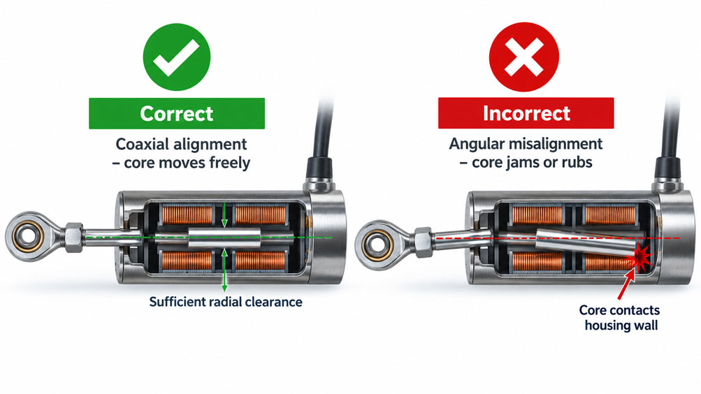
An inductive displacement transducer monitors the stroke of a hydraulic test cylinder. Under no-load conditions, the sensor provides a stable and repeatable measurement. However, deviations occur during actual testing. As the stroke increases, the output signal initially changes smoothly before individual readings suddenly jump. When the cylinder retracts, the displacement transducer sometimes indicates a different value than during the preceding forward stroke. Occasionally, the indication even remains stationary for a short time although the actuator continues to move.
The cause may lie in the mechanical coupling between the moving machine component and the sensor core. A conventional LVDT (Linear Variable Differential Transformer) detects the axial position of a magnetically active core within a coil assembly. In a free-core configuration, the actual displacement measurement is contactless. The core should therefore not make mechanical contact with the inner wall of the sensor bore anywhere along the measuring stroke.
Insufficient alignment, a bent connecting rod or lateral movement of the actuator can cause the core to contact the bore wall. This results in friction, mechanical hysteresis and potentially temporary sticking. Similar faults can occur in inductive displacement probes with guided contact rods due to excessive side loads, contaminated guides or unsuitable mechanical loading.
Electrical signal conditioning cannot reliably eliminate these mechanical problems. Additional filtering may smooth sudden changes in measured values, but it cannot correct a sticking core guide or incorrect mechanical force transmission. Troubleshooting must therefore consider the entire measurement chain: machine movement, mechanical guidance, core or probe rod, inductive sensing element, connecting cable and signal conditioning electronics.
This technical article explains how to identify and prevent mechanical causes of sticking or rubbing LVDT cores. It focuses on core clearance, axial alignment, angular misalignment, side loads, guidance concepts and mechanical couplings. A calculation example demonstrates how even a small angular misalignment over a longer connecting distance can cause the core to contact the sensor bore. Dynamic loads, thermal expansion, electrical signal conditioning, calibration and suitable inductive displacement sensors from the ICS product range are also discussed.
Table of Contents
- Define the Displacement Measurement Task and Mechanical Motion
- Understand the LVDT Measuring Principle and Contactless Core Detection
- Distinguish Conventional LVDTs from Inductive Half-Bridge Sensors
- Distinguish Free-Core, Guided-Core and Spring-Loaded Displacement Probes
- Identify Typical Causes of a Sticking or Rubbing Core
- Correctly Evaluate Axial Alignment, Parallel Offset and Angular Misalignment
- Determine Radial Core Clearance and Required Freedom of Movement
- Calculation Example: How Small Angular Misalignment Causes Core Rubbing
- Correctly Mount the Sensor Housing and Moving Core
- Keep Side Loads and Bending Moments Away from the Measuring Assembly
- Select Suitable Linear Guides, Joints and Probing Mechanisms
- Consider Core Extension Material and Geometry
- Check Thermal Expansion and Temperature-Related Axis Displacement
- Evaluate Vibration, Acceleration and Dynamic Core Behaviour
- Identify Contamination, Abrasion and Damaged Sensor Bores
- Correctly Design Measuring Stroke, End Positions and Mechanical Stops
- Check Excitation Signals, Demodulation and Electrical Signal Conditioning
- Investigate Mechanical Faults and Electrical Signal Faults Separately
- Evaluate Linearity, Repeatability, Hysteresis and Calibration
- Perform a Systematic Testing and Commissioning Procedure
- Diagnose Typical Fault Patterns and Misinterpretations
- Suitable Inductive Displacement Transducers and Alternatives from ICS Schneider
- Conclusion: Check Core Guidance and Alignment Before Electrical Readjustment
- Frequently Asked Questions About Sticking LVDT Cores and Inductive Displacement Sensors
1. Define the Displacement Measurement Task and Mechanical Motion
Inductive displacement transducers are used to detect linear movements, positions and strokes within machines and test benches.
Typical applications include monitoring hydraulic cylinder positions, measuring valve travel, industrial testing equipment, assembly systems and detecting mechanical deformation.
Before selecting a displacement transducer, it is first necessary to establish which movement actually needs to be measured.
A hydraulic cylinder, for example, may perform a nominally straight stroke. However, additional lateral movements, slight tilting or elastic deformation may occur in the actual machine.
If a sensor core is rigidly connected to such a machine component, these additional movement components can be transferred to the sensor assembly.
However, a conventional LVDT with a free core is primarily designed to detect axial relative movement between the core and the coil housing.
The mechanical connection must therefore be designed so that the core remains sufficiently free inside the sensor bore throughout the entire measuring stroke.
In a guided inductive displacement probe, an integrated guide performs part of the mechanical guidance function. However, it also has permissible load limits.
Selection must therefore consider not only measuring stroke, accuracy and output signal but also the actual directions of movement, side loads, accelerations and installation conditions.
Particularly on test benches, displacement measurement should be evaluated under realistic load conditions. A sensor assembly that operates correctly without load may behave differently when the machine deforms under stress.
2. Understand the LVDT Measuring Principle and Contactless Core Detection
A conventional LVDT consists of a primary winding and two secondary windings arranged symmetrically with respect to the primary winding.
The primary winding is excited using a suitable AC voltage.
A movable ferromagnetic core influences the magnetic coupling between the primary and secondary windings.
The two secondary windings are normally connected electrically so that their voltages can be evaluated differentially.
When the core is in its electrical centre position, the induced secondary voltages are equal in magnitude under idealised conditions. The resulting differential voltage is then close to zero.
When the core moves axially, the coupling to the two secondary windings changes.
This produces a position-dependent differential voltage. The relative phase relationship with respect to the excitation signal also makes it possible to distinguish the two directions of movement around the electrical null position.
Suitable signal conditioning converts this AC voltage signal into a corresponding position value or an output signal suitable for industrial use.
One essential feature of the free-core LVDT configuration is contactless magnetic position detection.
During intended operation, the core does not need to rub against a measuring track or rest on an electrical contact.
As long as it moves without contact inside the designated sensor bore, the measuring principle itself produces no mechanical friction.
Practical resolution is limited particularly by the noise characteristics of the evaluation electronics, signal processing and the other characteristics of the measurement chain.
These advantages are lost if unsuitable mechanical coupling forces the core against the inner wall of the sensor bore.
3. Distinguish Conventional LVDTs from Inductive Half-Bridge Sensors
In general usage, the term LVDT is often applied to different types of inductive displacement sensors.
Technically, however, a conventional differential transformer must be distinguished from other inductive displacement transducers.
A conventional LVDT operates with one primary winding and two differentially connected secondary windings.
Other inductive displacement transducers use, for example, a half-bridge arrangement with two inductive coil sections.
In these sensors, a movable magnetically active core can also change the distribution of inductance.
However, electrical evaluation is performed according to the particular sensor principle.
This means that two displacement transducers may look mechanically similar while requiring different excitation signals, connections and evaluation electronics.
The ICS product range includes various inductive displacement sensors from the ISM series.
For example, the ISM24 series describes the axial movement of a NiFe core inside a coil assembly. The resulting inductance distribution is converted into a displacement-proportional signal using suitable external electronics.
The ISM205 is explicitly described as an inductive half-bridge displacement transducer.
The mechanical requirements for core clearance, alignment and guidance can be comparable between these designs.
However, the associated electrical specifications are not automatically identical.
Before replacing a sensor or electronic unit, the actual sensor construction and electrical compatibility must therefore be checked.
4. Distinguish Free-Core, Guided-Core and Spring-Loaded Displacement Probes
Different mechanical configurations are available for inductive displacement measurements.
The selected design directly influences how movement is transmitted to the sensor and which additional forces may occur.
| Configuration | Mechanical Principle | Advantages | Typical Risks |
|---|---|---|---|
| LVDT with free core | Core moves without intended contact inside the coil bore | No internal sensor friction with correct guidance; high repeatability | Axial misalignment, core extension deflection, wall contact |
| LVDT with guided core | Moving core or core carrier is mechanically guided | Easier mechanical integration, defined movement path | Guide friction, wear, limited permissible side loading |
| Spring-loaded inductive displacement probe | Guided probe rod follows the workpiece surface with a defined contact force | Suitable for contact measurement without a rigid connection to the workpiece | Stick-slip, changes in contact force, side loading, guide wear |
| Inductive displacement sensor with integrated electronics | Inductive measuring principle with internal signal conditioning | Simplified electrical integration, standardised output signal depending on type | Mechanical faults remain possible; output filters can conceal faults |
| Inductive displacement sensor with external electronics | Sensing element and signal conditioning are separate | Flexible physical arrangement and application-specific signal processing | Incorrect excitation, unsuitable electronics or interference-sensitive connecting cables |
With a free core, the external mechanical assembly must ensure that the core does not contact the sensor bore.
With a guided core, the integrated guidance performs part of this function. However, the permissible side loads must still be observed.
A spring-loaded displacement probe is particularly suitable when a moving workpiece only needs to be contacted for measurement.
A free core, on the other hand, may be advantageous when the measured object already has sufficiently precise guidance of its own.
The configuration should therefore be selected according to the actual mechanical measurement task rather than solely according to the required measuring range.
5. Identify Typical Causes of a Sticking or Rubbing Core
An LVDT core can contact the sensor bore or become blocked within the measuring stroke for various mechanical reasons.
One particularly common cause is insufficient alignment between the sensor housing and the moving core.
If the core axis is inclined relative to the sensor axis, the radial deviation can increase along the movement path.
A parallel axis offset can also be problematic if the distance between the axes uses up too much of the available core clearance.
Other possible causes include a bent core extension, damaged mounting components, excessive side loads or a mechanically deformed sensor sleeve.
With an excessively long and thin connecting rod, even its own weight can cause relevant deflection.
Dynamic forces resulting from acceleration and vibration can also change the alignment.
Additional fault sources occur with guided displacement probes, including damaged sliding or ball guides and contamination of the probe rod.
A mechanically sticking core can produce different electrical symptoms.
These include sudden measurement changes, different indications during forward and return strokes and apparently reduced repeatability.
However, the output signal alone does not always clearly indicate whether mechanical contact is present.
Reliable diagnosis therefore requires investigation of the actual relative movement between the core, housing and machine component.
6. Correctly Evaluate Axial Alignment, Parallel Offset and Angular Misalignment
For reliable LVDT measurement, the core movement axis must be suitably aligned with the axis of the sensor bore.
Two fundamental geometrical deviations must be distinguished.
With parallel offset, the axes are approximately parallel but displaced laterally relative to each other.
With angular misalignment, the axes are not parallel. The radial deviation changes along the length being considered.
Both effects can occur simultaneously.
A small parallel offset does not necessarily cause a significant electrical measurement error with a free-core LVDT.
As long as the core remains completely within the specified mechanical clearance, inductive measurement can continue to operate reliably.
However, maintaining mechanical clearance without contact is essential.
Angular misalignment is also not automatically acceptable merely because the sensor provides plausible readings at a single measurement point.
The core position may change during the stroke. Radial clearance that is initially sufficient may be exhausted at another position.
This effect is particularly important with long core extensions.
Alignment should therefore be checked throughout the entire intended stroke.
Possible changes in position caused by machine deformation, temperature and dynamic loading must also be considered.
Reliable installation does not necessarily require mathematically perfect centring. What matters is that the geometrical and metrological limits specified by the sensor manufacturer are maintained throughout the complete operating range.
7. Determine Radial Core Clearance and Required Freedom of Movement
In a free-core LVDT, a defined radial clearance exists between the core and the inner wall of the sensor bore.
This clearance allows contact-free axial movement.
For a simplified circular cross-section, the theoretical radial clearance can be calculated from the diameters:
sradial = (Dbore − Dcore) / 2
Here, Dbore is the internal diameter of the sensor bore and Dcore is the outside diameter of the core.
Initially, this formula describes only the geometrical difference between ideally circular and concentric components.
In practice, additional influences must be considered.
These include manufacturing tolerances, possible out-of-roundness, thermal expansion, core inclination, deflection and the actual position of the complete core extension.
The sensor bore must also not be deformed by unsuitable mounting.
The full theoretical clearance between the core and bore should therefore not be used up by mounting deviations without maintaining an appropriate safety margin.
The permissible radial deviation must be evaluated for the specific sensor configuration using the manufacturer’s specifications.
It is particularly important that an LVDT core must not be mechanically guided by contact with the bore wall.
With a free-core design, the required guidance must be provided by the intended external mechanism.
8. Calculation Example: How Small Angular Misalignment Causes Core Rubbing
A simplified geometrical example considers an LVDT with a free core and an external core extension.
The following dimensions are assumed for the model purely as illustrative values:
Internal diameter of the sensor bore: 4.20 mm
Outside diameter of the core: 3.80 mm
Initial radial axis offset: 0.05 mm
Axial length considered: 40 mm
The calculated radial clearance is:
sradial = (4.20 mm − 3.80 mm) / 2 = 0.20 mm
For a simplified rigid and straight core extension, the lateral deviation caused by angular misalignment can be calculated approximately as:
eangle = L · tan(α)
For the unfavourable case in which the initial offset and angular deviation add together in the same direction:
etotal = e0 + L · tan(α)
Here, L is the axial length considered and α is the angle between the two axes.
At an angle of 0.20°, the result is:
etotal = 0.05 mm + 40 mm · tan(0.20°)
etotal ≈ 0.190 mm
Under this model assumption, only approximately 0.010 mm remains of the original radial clearance of 0.20 mm.
Even small additional deviations could therefore cause contact.
| Angular Misalignment | Total Lateral Deviation After 40 mm | Calculated Remaining Clearance | Assessment |
|---|---|---|---|
| 0.00° | 0.050 mm | 0.150 mm | Geometrical clearance available |
| 0.10° | approx. 0.120 mm | approx. 0.080 mm | Reduced clearance margin |
| 0.20° | approx. 0.190 mm | approx. 0.010 mm | Contact possible with additional deviations |
| 0.25° | approx. 0.225 mm | approx. −0.025 mm | Geometrical interference in the rigid model |
At an angular misalignment of 0.25°, the calculated lateral deviation exceeds the assumed radial clearance.
In an idealised rigid arrangement, contact-free movement would therefore no longer be geometrically possible.
In reality, the components may deform elastically or move slightly out of position. This can result in friction, bending or increased mechanical loading.
The calculation example demonstrates why even small angular deviations can be critical when longer mechanical connections are used.
It describes only a simplified geometrical analysis and does not specify a permissible mounting deviation for any particular LVDT or ISM sensor.
For actual design, the core diameter, bore diameter, tolerances, core length, stroke position, thermal effects and complete guidance concept must be considered.
9. Correctly Mount the Sensor Housing and Moving Core
Correct sensor mounting must perform two functions: The sensor housing must be held in its intended position, while the core must remain sufficiently free to move along the defined measuring stroke.
The mounting arrangement must not cause impermissible mechanical deformation of the sensor housing.
Excessive clamping forces can be particularly problematic with cylindrical LVDT housings.
Under unfavourable conditions, local deformation may occur if a clamping screw applies a concentrated force directly to the sensor housing.
Manufacturers such as TE Connectivity therefore recommend suitable mounting blocks and controlled clamping forces.
Mounting the moving core is equally important.
The core or connecting rod must be attached so that the intended axial movement is transmitted without introducing excessive side loads.
If angular movement is present, a suitable articulated connection may be appropriate.
However, such a connection must match the specific sensor construction and measurement task.
An arbitrary joint is not automatically suitable because additional clearance or elastic deformation may cause measurement errors.
Particularly with small measuring strokes, even minor mechanical play in the connecting components can affect the required accuracy.
The threaded connection of the core extension must also not bend the core or alter its material properties.
Installation should therefore be carried out using the specified tools and in accordance with the manufacturer’s instructions.
10. Keep Side Loads and Bending Moments Away from the Measuring Assembly
An inductive displacement transducer is fundamentally designed to measure movement, not to withstand arbitrary mechanical forces.
However, lateral forces may occur if the mechanical connection is unsuitable.
Such side loads may arise from a slightly tilted actuator rod, a guide subjected to lateral loading or an incorrectly aligned machine axis.
With a free-core LVDT, these loads can cause the connecting rod to bend and the core to contact the sensor bore.
With a guided displacement probe, side loads act on the integrated mechanical guide instead.
This can lead to friction, guide wear and changes in contact force.
Bending moments are also relevant.
If a lateral force acts through a longer connecting rod, it may generate a substantial bending effect depending on the rod length, stiffness and support conditions.
A basic assessment should therefore consider not only the force but also its point of application.
For displacement measurement, it is preferable for the moving machine component to be supported by an appropriate machine guide.
The displacement transducer can then detect the relative position without being used as a mechanical guiding element.
Particularly on test benches, machine deformation caused by loading must also be considered.
A mechanical arrangement that is correctly aligned under no-load conditions may have a different relative axis position when test forces are applied.
11. Select Suitable Linear Guides, Joints and Probing Mechanisms
The mechanical guidance of an inductive displacement measurement point must match the actual movement.
In a free-core LVDT, the movement is frequently defined by an external machine guide.
The core is connected to the moving machine component using a suitable extension rod.
If the external guidance is sufficiently precise, the core can move without contacting the sensor bore.
If such guidance is not available or is unsuitable by design, a guided sensor configuration may be more appropriate.
In a guided LVDT, the movement of the core carrier is mechanically defined by dedicated guiding components.
Such configurations can reduce installation complexity.
However, permissible side loading and guide service life must be considered.
Spring-loaded inductive displacement probes are suitable for straightforward contact measurement tasks.
The probe rod is guided against the workpiece surface and follows its movement within the intended measuring range.
A suitable probe guide can provide low mechanical play and good repeatability.
However, the probe spring applies a force to the measured object.
With sensitive or elastic workpieces, this force can affect the measurement result.
Lateral movement of the workpiece surface may also place side loads on the probe tip.
If substantial lateral movement is expected, the complete probe geometry, including tip and guidance, must therefore be evaluated.
Selection should be based on the actual movement rather than solely on which configuration is mechanically easiest to install.
12. Consider Core Extension Material and Geometry
With a free-core LVDT, a mechanical extension rod is frequently used to connect the core to the moving machine component.
This extension affects not only mechanical guidance but potentially also the magnetic behaviour of the sensor.
A conventional LVDT operates using a magnetically active core.
Additional ferromagnetic materials close to the core can change the magnetic field distribution and therefore influence the measurement characteristic.
Highly electrically conductive materials may also affect signal transmission because of eddy currents.
In its installation instructions, TE Connectivity therefore explicitly points out that unsuitable ferromagnetic extension materials and certain highly conductive metals can impair LVDT performance.
If a custom core extension is manufactured, the material recommendations of the specific sensor manufacturer are therefore decisive.
Even stainless steels considered non-magnetic must be evaluated according to their actual properties.
For example, certain materials can develop magnetic properties as a result of machining or forming.
The extension rod must also have sufficient mechanical stiffness.
A very long, thin rod can bend under its own weight, side loads or acceleration.
This can in turn push the core against the sensor bore.
A suitable design therefore requires an appropriate material, sufficient mechanical stiffness and a mounting arrangement matched to the application.
If the core or core extension is replaced, it should also be checked whether the original sensor characteristic and calibration remain valid.
13. Check Thermal Expansion and Temperature-Related Axis Displacement
Temperature changes can affect the mechanical alignment of an LVDT measurement point.
When heated, the sensor housing, machine structure, mounting brackets and connecting rods expand according to their material properties.
If these components have different coefficients of thermal expansion or are heated unevenly, their relative positions can change.
Originally good axial alignment may also be affected as a result.
Particularly with long mechanical connections, small thermal expansions can cause relevant positional changes.
Another problem arises when the sensor mounting bracket is attached to a different machine structure from the guide supporting the moving core.
At different temperatures, the two structures may deform differently.
This can introduce additional parallel or angular misalignment.
The available core clearance may also change because the bore and core have different thermal expansion characteristics.
Suitable thermal design must therefore consider the intended temperature ranges of the entire mechanical assembly.
The electrical measurement characteristic of the sensor may also have a specified temperature dependence.
Mechanical and electrical temperature effects must be evaluated separately.
A temperature-dependent zero-point shift may result either from thermal changes in the mechanical assembly or from characteristics of the sensor and its electronics.
Diagnosis must therefore establish whether the actual core position remains unchanged or whether the mechanical assembly moves with temperature.
14. Evaluate Vibration, Acceleration and Dynamic Core Behaviour
In dynamic displacement measurements, the LVDT core frequently moves with changing velocity and acceleration.
The mechanical connection must be suitable for these conditions.
High accelerations generate additional inertial forces.
A long or flexible core extension may therefore be excited into vibration.
Even a small existing deflection may change under dynamic operating conditions.
This can result in temporary contact with the sensor bore.
Mechanical resonance is particularly problematic.
If the excitation frequency approaches a natural frequency of the core extension or mounting structure, relative movement can increase significantly.
High accelerations can also influence the contact force of guided displacement probes.
With a spring-loaded configuration, the probe tip may temporarily lose contact with the workpiece surface under unfavourable dynamic conditions.
Another limitation results from electrical signal conditioning.
The maximum movement frequency that can be measured meaningfully depends on the sensor, excitation, demodulation, filtering and data acquisition.
A mechanically correctly operating sensor may therefore still produce a delayed or attenuated indication if the electronic bandwidth is insufficient.
For dynamic diagnosis, mechanical core movement and the electrical output signal should be recorded in a way that allows their timing to be compared.
15. Identify Contamination, Abrasion and Damaged Sensor Bores
Contamination can also impair contactless inductive displacement measurement.
With open sensor bores, dust, abrasion particles or other contaminants may enter the core movement area.
If particles become trapped between the core and the inner wall, the available radial clearance may be reduced.
Depending on their size and characteristics, particles can cause friction or block movement.
Ferromagnetic particles can be particularly problematic.
They can cause mechanical interference and may also affect the magnetic properties of the measuring system.
Existing abrasion can also indicate unwanted contact with the bore wall.
If distinct rubbing marks appear on a core that is intended to operate without contact, the cause should be investigated in the mechanical guidance.
Contamination of the probe rod or guide can cause additional friction in guided displacement probes.
Cleaning must be performed according to the manufacturer’s instructions.
Unsuitable mechanical tools or aggressive cleaning agents can damage sensor surfaces or the core.
Applying lubrication without proper evaluation is also not necessarily appropriate.
A free LVDT core does not require lubrication for its intended contactless movement.
For guided configurations, only the maintenance and lubrication procedures specified for the particular guidance system may be performed.
The ingress protection rating of the sensor housing must also be interpreted correctly. A specified protection rating does not automatically mean that a mechanically open core bore is free from contamination risks under all conditions.
16. Correctly Design Measuring Stroke, End Positions and Mechanical Stops
The selected displacement transducer must be capable of measuring the entire intended movement range.
A distinction must be made between the usable electrical measuring stroke and the mechanically permissible movement limits.
In a conventional LVDT, the characteristic curve is particularly linear within a specified range.
Outside this range, the sensor may continue to generate a signal, but its accuracy or linearity may no longer meet the specified requirements.
The electrical upper or lower measuring limit is therefore not automatically equivalent to a mechanical stop.
Particularly with free cores, it is necessary to prevent the intended machine movement from pulling the core excessively far out of the bore or pushing it against an internal end region.
Some sensor designs may also be electrically overloaded if the core is positioned incorrectly. The respective manufacturer instructions are decisive.
The permissible mechanical stroke must also be observed with guided displacement probes.
Repeatedly reaching unsuitable end stops can damage guides, springs and probe mechanisms.
The displacement sensor itself should therefore not automatically be used to limit machine movement mechanically.
Suitable external stops and movement reserves may be necessary.
Particularly on dynamic test benches, overtravel, elastic deformation and possible continued movement after stopping must also be considered.
17. Check Excitation Signals, Demodulation and Electrical Signal Conditioning
An incorrect displacement indication is not necessarily caused by a sticking core.
Electrical signal conditioning can also produce deviations.
In a conventional AC LVDT, the primary winding is excited with a suitable alternating voltage.
The two secondary signals are evaluated differentially.
Suitable demodulation processes amplitude and phase relationships to produce an output value corresponding to the core position.
The excitation voltage and frequency must match the specific sensor.
Incorrect excitation or unsuitable signal conditioning can result in changes in sensitivity, offset or other measurement errors.
The cable between the sensing element and the electronics can also have an influence.
Suitable cables and shielding are particularly important for low-level AC voltage signals.
The permissible cable length and any required readjustments are instrument-specific.
Inductive half-bridge sensors have different electrical requirements from conventional differential transformers.
Each sensor type must therefore be operated with evaluation electronics expressly suitable for that sensor.
An arbitrary LVDT signal conditioner must not be used for a half-bridge sensor merely because the number of connections appears similar.
In sensors with integrated electronics, the necessary signal conditioning is performed inside the sensor housing.
Depending on the configuration, the output signal may be provided as a voltage or current, for example.
The electrical scaling must then match the PLC or measuring instrument being used.
Additional filtering can reduce electrical interference. However, it must not be used to conceal an actual mechanical sticking point.
18. Investigate Mechanical Faults and Electrical Signal Faults Separately
When an LVDT measurement is abnormal, mechanical causes and electrical faults should be investigated systematically and separately.
Comparing the indicated displacement with an independent reference is particularly helpful.
For example, if the position of a test cylinder is also measured using a suitable independent displacement measurement system, it is possible to determine whether the indicated LVDT displacement follows the actual movement.
If the machine continues moving while the LVDT value remains stationary, several causes are possible.
The core may actually be sticking, or the mechanical connection may have play or become loose.
However, an electrical signal failure is also possible.
Another observation is a difference in the displayed values during forward and return strokes.
This may indicate mechanical hysteresis, guide friction or faulty mechanical coupling.
An unsuitable measuring arrangement with play in joints or mounting components can also cause such effects.
Diagnosis should therefore include checking the relative movement of the core and sensor housing.
Where appropriate, it may be useful to investigate the sensor separately from the loaded machine mechanism.
Such comparisons may only be performed under suitable safe conditions and in accordance with manufacturer instructions.
It is particularly important not to damage sensitive LVDT cores by manually bending, pressing or improperly machining them.
Electrical testing conditions must also match the respective sensor type.
Reliable diagnosis therefore requires information about actual movement, the mechanical connection and the electrical signals.
19. Evaluate Linearity, Repeatability, Hysteresis and Calibration
Different metrological characteristics must be distinguished when evaluating an inductive displacement measurement point.
Linearity describes how far the actual characteristic curve deviates from the intended linear relationship between displacement and output signal.
Repeatability describes how consistently the same measurement value is obtained under identical test conditions.
Hysteresis describes a difference in the characteristic curve that depends on the previous direction of movement or the history of the applied load.
With a free LVDT core, the actual contactless measuring principle produces no mechanical sliding friction.
Nevertheless, the complete measuring arrangement may exhibit hysteresis, for example due to friction in an unsuitable core guide or play in the mechanical coupling.
With a guided displacement probe, corresponding friction and guidance effects must also be considered.
Calibration should therefore represent the intended mechanical measuring arrangement as realistically as possible.
For displacement calibration, defined positions can be approached using suitable reference movement equipment and an appropriately accurate reference measuring instrument.
In bidirectional testing, the measuring points are evaluated during both increasing and decreasing displacement.
This allows differences between the two directions of movement to become apparent.
A possible test plan includes several evenly distributed positions across the intended measuring range.
The actual number and distribution of test points depend on the measurement task, required uncertainty and applicable testing requirements.
The selected reference must also have sufficiently low measurement uncertainty.
A calibration result obtained exclusively with a freely moving, unloaded core does not automatically confirm measurement quality after installation in a mechanically stressed machine.
For demanding applications, additional testing of the complete installed measurement chain may therefore be required.
20. Perform a Systematic Testing and Commissioning Procedure
Commissioning an inductive displacement transducer should consider the mechanical construction, electrical signal processing and actual measuring function together.
The following procedure describes a general technical test sequence. Work on machinery may only be performed according to an appropriate safe procedure by suitably qualified personnel.
- Define the measurement task: Establish the required stroke, movement direction, accuracy, repeatability and dynamic response.
- Identify the sensor type: Distinguish between a conventional LVDT, inductive half-bridge, free core, guided core and displacement probe.
- Check manufacturer specifications: Record measuring range, core diameter, bore diameter, permissible movement and mechanical limits.
- Analyse machine movement: Check whether lateral movement, tilting or deformation occurs in addition to the axial movement.
- Review the mounting concept: Evaluate the position and mounting of the sensor housing and core extension.
- Investigate axial alignment: Check parallel offset and angular misalignment along the intended movement path.
- Evaluate radial core clearance: Ensure that the intended freedom of movement is maintained despite tolerances and dynamic influences.
- Check the core extension: Evaluate material, straightness, mechanical stiffness and suitable connection to the measured object.
- Evaluate side loads: Prevent the sensor from being subjected to loads as an unsuitable mechanical guiding element.
- Investigate guided components: For displacement probes, check the intended guides, contact forces and permissible side loading.
- Check movement limits: Ensure that the complete machine stroke remains within the permissible sensor and mechanical limits.
- Check temperature conditions: Consider possible thermal changes in axial alignment and the relative zero position.
- Evaluate vibration and acceleration: Investigate dynamic deflection and possible mechanical resonance.
- Inspect the sensor condition: Evaluate contamination, rubbing marks, damage and abnormal mechanical changes.
- Identify the electronics: Verify suitable excitation, demodulation or integrated signal conditioning.
- Check the signal path: Compare cable, shielding, supply and connection configuration with the manufacturer specifications.
- Check zero point and scaling: Verify the electrical relationship between core position and output signal under defined conditions.
- Compare displacement measurements: Evaluate the indication at several positions using a suitable independent displacement reference.
- Investigate forward and return strokes: Document repeatability, possible hysteresis and abnormal signal changes separately.
- Approve the measurement point: Document mechanical and electrical test results, limitations, measurement uncertainty and the approved configuration.
Testing across the complete intended stroke is particularly important.
Sufficient freedom of movement at the centre position does not automatically prove that the core will remain contact-free at both end positions.
Similarly, a measurement point checked under no-load conditions should also be evaluated under suitable representative operating conditions.
If rubbing or sticking is suspected, the mechanical cause must be properly eliminated before the measurement point is approved for its intended operation again.
21. Diagnose Typical Fault Patterns and Misinterpretations
Inductive displacement sensors can exhibit different fault patterns despite their fundamentally robust measuring principle. It is particularly important to distinguish between mechanical causes and electrical signal processing faults.
| Observation | Possible Cause | Suitable Check |
|---|---|---|
| Measured value briefly stops and then jumps forward | Mechanical sticking, stick-slip or play in the core connection | Check actual core movement and mechanical guidance using an independent displacement reference |
| Different values during forward and return strokes | Guide friction, mechanical hysteresis or connection play | Compare both directions of movement at defined positions |
| Core shows visible rubbing marks | Insufficient axial alignment, inadequate core clearance or deflection | Evaluate mounting geometry and the complete movement path |
| Sensor works when removed but not when installed in the machine | Mechanical stress, side loads or insufficient alignment | Investigate installation and machine loading conditions |
| Measurement deviation increases with stroke | Angular misalignment, bent core extension or electrical nonlinearity | Check alignment across the entire stroke and electrical characteristic separately |
| Fault occurs only under high test force | Machine deformation changes the relative axis position | Evaluate mechanical movement under representative loading |
| Guided displacement probe moves with difficulty | Side loading, contaminated guide or mechanical wear | Check guide condition and permissible side loads according to the manufacturer’s procedure |
| Measured value fluctuates during motor operation | Electromagnetic interference or dynamic machine movement | Investigate the electrical signal path and actual mechanical movement separately |
| Zero point changes with temperature | Thermal machine deformation or electrical temperature drift | Check relative core position and signal conditioning as a function of temperature |
| Sensor provides different values after replacing the extension rod | Unsuitable material or changed mechanical geometry | Evaluate magnetic properties, dimensions and calibration |
| Signal is very noisy even though the core remains stationary | Interference-sensitive wiring, unsuitable excitation or electronic fault | Check excitation signal, shielding and signal conditioning |
| Signal indication is delayed at high movement speeds | Insufficient measuring bandwidth or electronic damping | Compare sensor and electronic dynamics with the actual movement frequency |
The table describes possible causes and suitable checks. A definitive diagnosis must be performed on the specific measuring system.
It is particularly important to recognise that electrical zero adjustment does not correct mechanical axial misalignment.
Likewise, increased signal filtering may merely make an existing mechanical sticking point less visible in the display.
The reliable solution is to identify the actual mechanical or electrical cause and eliminate it specifically.
22. Suitable Inductive Displacement Transducers and Alternatives from ICS Schneider
22.1 ISM21: Compact Inductive Displacement Sensor with External Electronics
The ISM21 is a compact inductive displacement sensor for industrial measurement tasks.
The series is available with measuring strokes up to 20 mm and has a housing diameter of approximately 10 mm.
The sensor is operated with suitable external evaluation electronics.
Depending on the configuration, accuracy versions of 0.5 % or 0.25 % are available.
The ingress protection rating extends up to IP68 for appropriately designed versions.
The ISM21 is also available as a displacement probe.
This makes the series suitable for consideration in compact test benches, mechanical engineering applications and small linear movements.
The different mechanical configurations must be distinguished during selection.
For a free-core version, the required external guidance must be designed accordingly.
For a probe version, the mechanical guidance, probe travel and, where applicable, permissible side loading must be considered.
The electrical sensor and evaluation architecture must be defined according to the selected order configuration. The designation “inductive displacement sensor” alone does not confirm electrical compatibility with arbitrary conventional LVDT electronics.
22.2 ISM26: Inductive Displacement Sensor for Longer Strokes
The ISM26 is an inductive displacement sensor for linear measurement tasks involving longer strokes.
The series offers measuring strokes up to 200 mm and a housing diameter of approximately 12 mm.
The sensor is designed for use with external electronics.
A corresponding displacement probe version is also available.
Depending on the configuration, accuracy versions of 0.5 % or 0.25 % and ingress protection ratings up to IP68 are available.
The ISM26 may be suitable for longer movements in machines, test benches and appropriate hydraulic applications.
Mechanical guidance must be planned particularly carefully for larger measuring strokes.
Long core extensions can exhibit greater deflection due to their own weight, acceleration or side loads than shorter connections.
As a result, the requirements for axial alignment and external mechanical guidance may increase.
The suitable mechanical configuration and corresponding evaluation electronics must be selected for the specific installation.
22.3 ISM224: Inductive Displacement Probe with Precision Ball Guidance
The ISM224 is an inductive displacement sensor with a precision-guided probing mechanism.
The ICS product information describes a stainless steel clamping shank, precision ball guidance and a carbide measuring tip with an M2.5 connection.
Measuring strokes up to 20 mm are available depending on the configuration.
The sensor requires suitable external evaluation electronics.
The specified accuracy versions are 0.5 % and 0.25 %.
The integrated guidance can be particularly advantageous for repeated contact measurement operations.
It provides defined mechanical guidance of the probe rod and simplifies certain measuring arrangements.
However, precision ball guidance does not mean that arbitrary side loads can be accommodated.
Permissible mechanical loading and actual alignment must still match the application.
For measurement tasks involving predominantly axial probing movement, the ISM224 may provide an alternative to a custom-designed free-core guidance system.
22.4 ISM34: Miniature Displacement Transducer with Integrated Electronics
The ISM34 is a compact inductive displacement transducer with integrated signal conditioning.
It has a housing diameter of approximately 10 mm and is available with measuring strokes up to 20 mm.
The series is characterised by low operating current consumption.
Depending on the configuration, accuracy of ≤ ±0.5 % or ≤ ±0.25 % is specified.
Ingress protection up to IP67 is available for corresponding versions.
The integrated electronics simplify connection to a suitable downstream evaluation device.
This can reduce the need for separate external signal conditioning.
The design may be particularly suitable for compact machine modules and small test benches.
Even with integrated electronics, the mechanical requirements concerning core guidance, axial alignment and, where applicable, the probing mechanism remain relevant.
The specific mechanical configuration and output signal must be defined according to the intended instrument version.
22.5 ISM40: Inductive Displacement Transducer with Integrated Electronics for Strokes up to 200 mm
The ISM40 is a versatile inductive displacement transducer.
It has integrated electronics and is available with measuring strokes up to 200 mm.
The housing diameter is approximately 25 mm.
The series is also available as a displacement probe and is specified with IP66 ingress protection.
Depending on the configuration, accuracy versions of 0.5 % or 0.25 % are available.
For mechanical engineering and test bench applications, the combination of a longer measuring stroke and integrated signal processing can be advantageous.
Here, too, the mechanical sensor configuration must be selected according to the intended movement.
Particularly with large strokes, actual guidance conditions and possible dynamic loads must be considered.
Integrated signal conditioning simplifies electrical integration but does not replace correct mechanical installation.
22.6 ISM205: Miniature Displacement Sensor Based on the Inductive Half-Bridge Principle
The ISM205 is a compact inductive displacement sensor that explicitly operates according to the half-bridge principle.
The ICS product information specifies a measuring range of ±1.5 mm or optionally ±2 mm.
Linearity is ±0.5 % or ±0.25 %, depending on the configuration.
The documented construction includes a core approximately 3 mm in diameter with a corresponding mechanical extension.
The series is particularly suitable for consideration in applications involving short measuring strokes and compact mechanical installation conditions.
The ISM205 also demonstrates why a conventional LVDT must be distinguished from an inductive half-bridge sensor.
Both measuring principles can use an axially moving magnetically active core.
However, their electrical connection and evaluation requirements differ.
During selection, it must therefore be ensured that the signal conditioning used is explicitly compatible with the chosen sensor.
22.7 IWS12: Draw-Wire Displacement Sensor as an Alternative Measurement Solution
The IWS12 is an industrial draw-wire displacement sensor for longer linear movements.
The series covers measuring ranges from 100 to 3,000 mm.
Depending on the configuration, voltage outputs, current outputs and digital interfaces are available, among others.
Ingress protection IP67 is specified for suitable versions.
A draw-wire sensor operates according to a different mechanical principle from an LVDT.
The measuring cable is connected to the moving machine component and wound onto a dedicated mechanism.
This construction can be particularly useful for long strokes when a long rigid displacement transducer cannot be accommodated mechanically.
However, the direction of movement must also match the intended cable routing.
Unsuitable lateral cable deflection, angled tensile loading or incorrect mounting can impair its function.
The IWS12 is therefore not a direct replacement for every LVDT, but it may provide a suitable alternative displacement measurement solution for corresponding machine designs.
Additional displacement sensors and technical advice on selecting the measuring principle, mechanical coupling and signal conditioning are available from ICS Schneider in the Displacement Transducers / Position Sensors / Probes category.
23. Conclusion: Check Core Guidance and Alignment Before Electrical Readjustment
A conventional LVDT uses a robust inductive measuring principle and can detect the axial position of a movable core without contact.
This characteristic offers advantages in terms of repeatability and mechanical service life.
However, it requires the core to remain sufficiently free to move within the designated sensor bore.
With unsuitable mechanical coupling, axis offset, angular misalignment, side loads and deflection of a core extension can cause contact with the bore wall.
This results in friction, mechanical hysteresis and potentially a sticking core.
In guided inductive displacement probes, excessive side loading, contamination and worn guide components can also impair measurement quality.
Distinguishing between sensor configurations is therefore particularly important.
A free LVDT core requires suitable external movement guidance.
A guided core or displacement probe, on the other hand, has defined mechanical guidance whose load limits must be observed.
The sensor housing, core extension, material selection and thermal installation conditions must also be considered.
When a displacement indication is abnormal, the first step should be to determine whether the actual relative movement between the core and sensor housing corresponds to the intended movement.
Only then should it be assessed whether electrical scaling, zero-point correction or changes to signal conditioning are necessary.
Calibration must also reflect the actual measurement task.
Testing a sensor outside the machine does not automatically confirm measurement quality when it is installed and subjected to mechanical loading.
Define the measurement task → Distinguish sensor configurations → Check core clearance and movement range → Verify axial alignment throughout the stroke → Avoid side loads and bending moments → Select suitable guidance and mounting → Consider thermal and dynamic loads → Inspect sensor condition → Check compatible signal conditioning → Compare displacement with a reference → Evaluate forward and return strokes → Document the results
The most important practical principle is therefore: In a free-core configuration, an LVDT core should move without mechanical contact with the sensor bore. If the core sticks or rubs, the cause is often found in mechanical guidance or alignment rather than in the inductive measuring principle itself.
24. Frequently Asked Questions About Sticking LVDT Cores and Inductive Displacement Sensors
24.1 What Is an LVDT?
An LVDT is an inductive displacement transducer based on the differential transformer principle. A primary winding is excited with AC voltage. An axially movable magnetically active core influences the inductive coupling to two secondary windings. The core position is determined from their differential signal.
24.2 Why Can an LVDT Core Stick Even Though the Sensor Measures Without Contact?
In a free-core LVDT, electrical displacement measurement is contactless. However, the mechanical coupling of the core may be faulty. For example, axis offset, angular misalignment, deflection or side loads can cause the core to contact the inner wall of the sensor bore.
24.3 Must an LVDT Core Be Guided Exactly Through the Centre of the Sensor Bore?
Mathematically perfect centring is not necessary for every LVDT configuration. What matters is that the core remains within the specified mechanical clearance and achieves the intended measurement accuracy. In a free-core configuration, the core must not rub against the bore wall during normal operation.
24.4 What Is the Difference Between a Free-Core and a Guided-Core LVDT?
With a free core, the necessary mechanical guidance is provided by the external machine structure. In a guided configuration, the sensor or core carrier has its own mechanical guidance. This can simplify installation but introduces additional considerations relating to guide friction and permissible side loading.
24.5 Can Side Loads Damage an LVDT?
Yes. Unsuitable side loads can bend a core extension or push the core against the sensor bore. In guided displacement probes, they can place mechanical stress on the guidance system. This can cause friction, wear and measurement deviations.
24.6 How Can I Recognise a Sticking LVDT Core?
Possible indications include sudden changes in measured values, a temporarily stationary reading, different indications during forward and return strokes, or visible rubbing marks. However, these symptoms are not definitive. Actual core movement should be compared with a suitable independent displacement reference.
24.7 What Causes Hysteresis in an LVDT?
In a correctly functioning free-core LVDT, the contactless measuring principle itself produces no mechanical sliding friction. However, hysteresis in the complete measuring arrangement can result from guide friction, connection play, elastic deformation or unsuitable mechanical coupling. The evaluation electronics must also be considered.
24.8 What Does Stick-Slip Mean in an Inductive Displacement Sensor?
Stick-slip describes alternating sticking and sliding behaviour. It may occur in frictional guides or at an unintended contact point. Movement then becomes uneven and partly discontinuous. This can appear as a sudden measurement jump or delayed position change.
24.9 How Do I Calculate the Radial Clearance of an LVDT Core?
For ideally circular components, the geometrical radial clearance is half the difference between the bore diameter and core diameter. Manufacturing tolerances, axis offset, angular misalignment and dynamic deformation must also be considered in the actual installation.
24.10 Why Is Small Angular Misalignment Problematic with Long Core Extensions?
Angular misalignment causes increasing lateral deviation over a longer axial distance. This can exhaust the available radial core clearance. Long or flexible core extensions must therefore be guided carefully and evaluated for possible deflection.
24.11 Can I Restore a Sticking LVDT Core to Working Condition by Lubricating It?
A free LVDT core does not require lubrication for its intended contactless movement. If it rubs, the mechanical cause must be identified. For guided sensors, only maintenance and lubrication procedures specified by the manufacturer may be used.
24.12 Can Magnetic Materials in a Core Extension Affect the Measurement?
Yes. Ferromagnetic materials near an LVDT core can influence magnetic coupling. Certain highly electrically conductive materials can also have effects due to eddy currents. Material selection must therefore follow the recommendations of the respective sensor manufacturer.
24.13 Why Does the LVDT Zero Point Change with Temperature?
Possible causes include thermal expansion of the sensor mounting, machine structure and core extension, as well as the specified temperature dependence of the sensing element or electronics. Mechanical and electrical causes should be investigated separately.
24.14 Is an Inductive Half-Bridge the Same as a Conventional LVDT?
No. Both sensor types may use a movable magnetically active core, but they differ in their electrical winding arrangements and signal processing. A conventional LVDT uses a primary winding and two secondary windings. A half-bridge sensor requires evaluation electronics compatible with its particular principle.
24.15 Can I Repair an LVDT Simply by Adjusting the Electrical Zero Point?
Zero-point adjustment can correct an electrical indication offset, but it cannot eliminate mechanical axis offset, a sticking guide or a bent core extension. If mechanical abnormalities are present, the underlying cause must be corrected first.
24.16 How Should an Inductive Displacement Transducer Be Calibrated?
Calibration is performed by comparing defined displacement positions with a suitable reference. For demanding measurement tasks, several test points should be investigated during both forward and return strokes. Where necessary, the complete installed measurement chain should also be tested under representative mechanical conditions.
24.17 Which Suitable Displacement Sensors Does ICS Schneider Offer?
The ICS product range includes the ISM21 and ISM26 inductive displacement sensors with external electronics, the precision-guided ISM224 and the ISM34 and ISM40 series with integrated electronics. The ISM205 inductive half-bridge sensor is also available for short measuring strokes. As an alternative measurement technology for longer movements, ICS offers the IWS12 draw-wire displacement sensor, for example.
24.18 What Information Does ICS Schneider Need to Select the Correct Displacement Transducer?
The required information includes the complete measuring stroke, desired accuracy, repeatability, movement frequency and required dynamic response. The actual mechanical movement, available installation length, housing mounting, core guidance, possible side loads, axis offset and angular misalignment are particularly important. Temperature, vibration, ingress protection and possible contamination must also be considered. For selecting the electronics, the inductive sensor principle, required supply, output signal, cable length, PLC connection and any calibration and measurement uncertainty requirements are needed. If problems already exist, photographs of the installation, a description of the guidance arrangement and measurement recordings from forward and return strokes are helpful.