


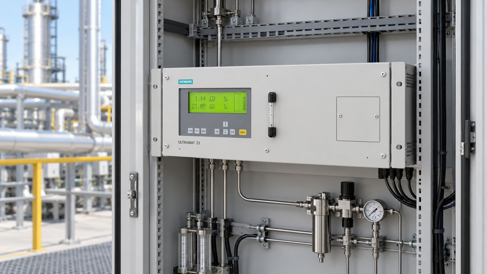
An industrial gas analyzer continuously monitors the concentration of sulfur dioxide in a moist process gas. The measuring system includes a heated sample gas line, a sample gas cooler, a water separator and an analysis filter. The analyzer itself operates reliably and provides the expected readings when calibration gas is applied directly. However, during normal process operation, the measured SO₂ concentrations repeatedly fall below the expected values.
Initially, a problem with the measuring cell is suspected. However, further investigation reveals that the deviation already occurs within the sample gas conditioning system. During cooling, some of the water vapor in the process gas condenses. The condensate is properly separated and drained. At the same time, however, part of the sulfur dioxide dissolves in the resulting liquid. Consequently, this measured component no longer reaches the analyzer in its entirety.
A water separator can therefore reliably protect a gas analyzer against liquid ingress while still causing a systematic measurement error. Particularly with water-soluble or reactive gases such as SO₂, NO₂, NH₃, HCl and H₂S, interactions between the gas phase, condensate and wetted surfaces must be considered.
The opposite situation is also problematic. If moisture is not sufficiently removed, liquid droplets may enter the measuring cell, block filters or damage sensitive sensors. Inadequate condensate drainage can also affect the sample gas flow rate and increase response times.
A properly designed sample gas conditioning system must therefore fulfil two requirements simultaneously: It must keep the analyzer within its permissible operating conditions while transferring the gas components relevant to the measurement task with as little alteration as possible.
This technical article explains how water separators and sample gas coolers should be used in industrial gas analysis systems. It focuses on condensation, dew point, solubility of measured components, condensate drainage, filtration, sample gas flow and the distinction between wet-basis and dry-basis concentration values. A calculation example demonstrates why an analyzer may indicate a significantly lower concentration after gas drying despite functioning correctly. Testing procedures, calibration, diagnostics, safety requirements and suitable gas analyzers from the ICS product range are also discussed.
Table of Contents
- Define the Measurement Task and the Gas Components That Must Be Preserved
- Consider the Complete Gas Path from the Process to the Analyzer
- Understand Water Vapor, Dew Point and Condensation
- Distinguish Water Separators, Sample Gas Coolers and Gas Dryers
- Correctly Select the Sample Gas Dew Point and Required Cooling Capacity
- Prevent Washout of Water-Soluble Measured Components
- Correctly Distinguish Wet-Basis and Dry-Basis Gas Concentrations
- Calculation Example: SO₂ Concentration Before and After Condensate Separation
- Evaluate Droplet Separation, Liquid Films and Dead Volume
- Design Condensate Collectors, Drain Valves and Condensate Pumps
- Check Sampling Probes, Heated Sample Gas Lines and Line Routing
- Consider Material Compatibility, Adsorption and Chemical Reactions
- Coordinate Analysis Filters, Sample Gas Pumps and Flow Monitoring
- Distinguish NDIR, UV, Electrochemical and Paramagnetic Sensors
- Evaluate Sample Gas Volume, Dead Time and Dynamic Response
- Define Condensate Monitoring, Fault Indications and Alarm Behaviour
- Correctly Plan Calibration Gas Introduction Before and After Gas Conditioning
- Evaluate Systematic Concentration Losses and Measurement Uncertainty
- Consider Corrosive Condensate, Explosion Protection and Safe Disposal
- Perform a Systematic Testing and Commissioning Procedure
- Diagnose Typical Fault Patterns and Misinterpretations
- Suitable Process Gas Analyzers and Measurement Solutions from ICS Schneider
- Conclusion: Remove Condensate While Preserving the Sample Gas Composition
- Frequently Asked Questions About Gas Analyzers with Water Separators
1. Define the Measurement Task and the Gas Components That Must Be Preserved
Before selecting a water separator, it is essential to establish exactly which components in the process gas must be measured.
An industrial gas analyzer may determine oxygen, carbon monoxide, carbon dioxide, nitrogen oxides, sulfur dioxide, methane or hydrogen sulfide, for example.
The individual gases have different physical and chemical properties.
These differences are particularly important for sample gas conditioning.
One gas may remain largely in the gas phase during cooling, while another measured component may partially dissolve in the resulting condensate.
Consequently, a water separator suitable for oxygen or carbon monoxide measurement may be problematic when measuring low SO₂ or NH₃ concentrations.
Whether a measured gas component is transparent or invisible to the human eye provides no information about its solubility in water.
For correct system design, at least the target gas components, their concentration ranges and the composition of the carrier gas must be known.
Process pressure, temperature, moisture content, possible aerosols and condensable substances are also relevant.
It is equally important to establish whether the measurement result should be expressed on a wet-gas or dry-gas basis.
For emissions measurement, prescribed reference conditions may apply, while process control may require the actual concentration under operating conditions.
The intended use of the measured values is particularly important.
Are the values used solely for process monitoring, or do they influence a control function, fault indication or safety-related measure?
The greater the importance of the measurement for safety, environmental monitoring or product quality, the more important it becomes to demonstrate that the gas conditioning system does not introduce unacceptable systematic errors.
2. Consider the Complete Gas Path from the Process to the Analyzer
In extractive process gas analysis, a partial gas stream is withdrawn from the actual process.
This gas stream is transported to the analyzer through a sample gas line and, where necessary, several conditioning components.
A typical sample gas path may be arranged as follows:
Process → Sampling probe → Heated sample gas line → Sample gas cooler → Condensate separator → Analysis filter → Sample gas pump → Flow monitoring → Gas analyzer → Suitable gas outlet
The actual sequence depends on the system design.
For example, the sample gas pump may be installed before or after certain conditioning components.
Additional pressure regulators, protective filters, check valves and sample gas distributors may also be required.
With certain gas compositions, the sampling system must be heated to prevent condensate formation before the intended conditioning stage.
Otherwise, an uncontrolled temperature drop inside the sample gas line may cause liquid to form before the gas even reaches the water separator.
The sample gas composition may already change inside the line as a result.
A downstream water separator may remove this liquid but cannot automatically return the measured components already dissolved in it to the gas phase.
Evaluation of a sample gas conditioning system must therefore begin at the process connection.
Testing the gas analyzer alone is insufficient to confirm the integrity of the extracted process gas sample.
3. Understand Water Vapor, Dew Point and Condensation
Process gases can contain substantial quantities of water vapor.
As long as the water remains entirely in the gaseous state, it forms part of the gas phase.
When the gas is cooled under suitable pressure conditions, its relative humidity increases.
Once the dew point is reached, water vapor begins to condense.
Further cooling can produce additional liquid.
This relationship is particularly important in extractive gas analysis.
Hot, moist exhaust gas may cool down while passing through a sample line that is not heated sufficiently.
This causes liquid droplets or continuous condensate films to form on the inner walls.
The liquid may accumulate in lower sections of the line or be carried along by the gas stream.
Both conditions can be problematic.
Liquid accumulations can reduce the flow cross-section and restrict gas transport.
Entrained droplets can affect filters, pumps or the measuring cell of the analyzer.
Water-soluble gas components may also transfer into the liquid.
The dew point therefore not only characterises the moisture condition of the gas but also influences the entire sampling and measurement strategy.
The pressure dependence of the dew point is also important.
A temperature specification alone is not always sufficient. For correct evaluation, the pressure conditions at the respective point in the gas path must be considered.
4. Distinguish Water Separators, Sample Gas Coolers and Gas Dryers
In practice, different components are used to remove liquid or water vapor from sample gas.
However, they do not all perform the same function.
A simple water separator removes existing liquid droplets or accumulated condensate from a gas stream.
It does not automatically remove all gaseous water vapor.
A sample gas cooler, on the other hand, deliberately reduces the gas temperature so that water vapor condenses and can subsequently be separated.
Other methods use suitable membranes or keep the gas above its dew point until measurement takes place.
| Method | Operating Principle | Advantage | Important Considerations |
|---|---|---|---|
| Mechanical water separator | Separates existing liquid droplets | Protects downstream components against liquid condensate | Gaseous moisture largely remains; washout losses that have already occurred are not reversed |
| Sample gas cooler with condensate drainage | Controlled cooling and condensation of water vapor | Defined outlet dew point and continuous moisture reduction | Water-soluble measured components may be lost in the condensate |
| Membrane dryer | Selective transport of water vapor through a suitable membrane | Moisture reduction without conventional condensate collection may be possible | Possible substance transfer, material compatibility and losses of certain measured components must be checked |
| Heated wet-gas sampling system | Gas path remains above the relevant dew point | No intentional condensation within the heated transport path | Analyzer and complete gas path must be suitable for moist and hot operating conditions |
| Dilution sampling | Controlled mixing with a suitable dry gas | Can reduce dew point and concentration levels for appropriate measuring methods | Dilution ratio, measurement uncertainty and chemical sample integrity must be verified |
Selection must therefore not be based solely on which method achieves the lowest moisture content.
A method may be highly effective at reducing moisture while still being unsuitable for a particular measured component.
Particularly with reactive or highly water-soluble gases, heated wet-gas measurement or a specially designed conditioning method may offer advantages.
The appropriate solution depends on the measured component, analytical principle and actual reference conditions required.
5. Correctly Select the Sample Gas Dew Point and Required Cooling Capacity
A sample gas cooler is frequently used to reduce the dew point of moist process gas to a stable value.
Outlet dew points of a few degrees Celsius are commonly used in various conventional extractive gas analysis applications.
For example, a suitable cooler may be designed for an outlet dew point of approximately +3 to +5 °C.
However, these values are not universal requirements for all gas analyzers.
The required dew point depends on the permissible gas conditions of the analyzer being used and the properties of the measured components.
Insufficient cooling capacity can result in excessive water vapor remaining downstream of the cooler.
If the downstream line then becomes colder than the prevailing dew point, condensation may occur again.
Excessive or unsuitable cooling, on the other hand, can increase the risk of undesirable substance losses.
Particularly with water-soluble measured components, cooling temperature, residence time and heat exchanger design must therefore be evaluated together.
The actual gas flow rate is also important.
A sample gas cooler can only maintain its intended outlet dew point if the supplied heat and moisture loads remain within its specifications.
If the sample gas flow rate increases significantly, the cooling capacity may become insufficient.
A higher inlet temperature or changes in water content also affect the cooling capacity required.
Suitable design therefore requires information about sample gas flow rate, inlet temperature, water content, ambient conditions and desired outlet dew point.
It is also important to recognise that the analyzer itself may have additional moisture requirements.
For certain electrochemical O₂ sensor versions of the ULTRAMAT 23, Siemens specifies a required water vapor dew point of at least +2 °C while simultaneously requiring the sample gas to remain free of condensation.
Complete drying is therefore not the correct approach for this particular sensor configuration.
6. Prevent Washout of Water-Soluble Measured Components
When water vapor condenses, direct contact occurs between the gas phase and liquid water.
Certain gas components can dissolve in this water.
In sample gas conditioning, this process is commonly referred to as washout.
This is particularly relevant for SO₂, NO₂, HCl, NH₃ and, under appropriate conditions, H₂S.
The actual losses depend on the measured component, its concentration and the chemical conditions of the condensate.
The contact time between gas and liquid also influences mass transfer.
Another important parameter is the available contact surface area.
Many small liquid droplets can collectively provide a large exchange surface.
Depending on the gas and operating conditions, a relevant proportion of the measured component may therefore transfer from the gas phase into the condensate.
Dissolved gases may also react chemically with constituents of the condensate.
Henry’s law can be used to describe simple gas-liquid equilibria.
Under defined conditions, it establishes a relationship between the partial pressure of a dissolved gas component and its equilibrium concentration in the liquid.
For complete design calculations, however, the specific definition of the Henry’s law constant, temperature, gas composition and any relevant chemical equilibria must be considered.
For reactive gases, a simple solubility calculation alone is often insufficient.
The design of the sample gas cooler is therefore particularly important in practice.
An appropriately optimised heat exchanger can provide the necessary moisture reduction while limiting undesirable contact between the measured gas components and the condensate.
Manufacturers of specialised sample gas coolers therefore offer versions with reduced washout for water-soluble components such as SO₂.
Such performance must be demonstrated for the specific application.
A conventional water separator or standard sample gas cooler is not automatically suitable for low-loss transmission of very small SO₂ or NH₃ concentrations.
7. Correctly Distinguish Wet-Basis and Dry-Basis Gas Concentrations
In gas analysis, concentrations expressed on a wet-gas basis must be distinguished from those expressed on a dry-gas basis.
A wet-basis gas concentration includes water vapor as part of the total gas mixture.
For a dry-basis gas concentration, the water content is excluded from the reference quantity.
As a result, the numerical values differ even when the measured component is completely preserved during gas drying.
For an idealised gas composition, the relationship can be expressed as follows:
cdry = cwet / (1 − xH2O)
Here, xH2O denotes the molar or volumetric fraction of water vapor in the wet gas under the corresponding reference conditions.
The equation assumes that no measured component is lost during water removal and that no other changes in composition occur.
If a process gas contains 10 vol.% water vapor, for example, the remaining gas components account for 90 % of the total.
In the idealised model, a concentration of 90 ppmv on a wet basis therefore corresponds to:
cdry = 90 ppmv / 0.90 = 100 ppmv
Removing water vapor therefore increases the relative concentration of the remaining dry gas components.
This normal change must not be confused with washout.
When actual washout occurs, part of the measured component is additionally removed from the gas stream.
A simple moisture correction cannot automatically recover this loss.
For emissions measurements in particular, the prescribed reference conditions must also be considered, such as standard conditions and, where applicable, oxygen reference correction.
Conversion from wet to dry basis and any subsequent mathematical oxygen reference correction are separate processing steps.
8. Calculation Example: SO₂ Concentration Before and After Condensate Separation
A simplified example considers an extractive SO₂ measurement point monitoring a moist process gas.
At the sampling point, the actual SO₂ concentration is 90 ppmv on a wet basis.
The water vapor content is 10 vol.%.
The extracted gas is transported through a heated sample gas line to a cooler with a water separator.
For this calculation example, it is assumed that the water content is ideally removed completely during conditioning.
If SO₂ is fully preserved during this process, the resulting dry-basis concentration should be:
cSO2,dry = 90 ppmv / (1 − 0.10)
cSO2,dry = 100 ppmv
Under the assumed ideal mass balance, the analyzer should therefore indicate 100 ppmv on a dry basis.
However, the instrument actually indicates only 80 ppmv downstream of the gas conditioning system.
For the simplified model, it is assumed that the entire additional deviation results from loss of the measured component during condensation.
The relative concentration loss compared with the theoretically expected dry-basis value is therefore:
Loss = (100 ppmv − 80 ppmv) / 100 ppmv · 100 %
Loss = 20 %
The following table compares the different conditions.
| Measurement Condition | SO₂ Concentration | Reference Basis | Assessment |
|---|---|---|---|
| Process gas before conditioning | 90 ppmv | Wet gas containing 10 vol.% H₂O | Assumed actual initial concentration |
| After ideal removal of water vapor | 100 ppmv | Dry gas | Theoretical value without SO₂ loss |
| After actual conditioning in the example | 80 ppmv | Dry gas | Additional assumed SO₂ loss |
| Deviation from the ideal dry-basis value | −20 ppmv | Dry gas | 20 % lower indication than the expected concentration |
| Conversion of the incorrect reading back to wet basis | 72 ppmv | Wet basis with original 10 vol.% H₂O | 18 ppmv below the actual 90 ppmv |
If the measured value of 80 ppmv were simply converted back to a wet basis using the original water content, the result would be:
cwet,calculated = 80 ppmv · 0.90 = 72 ppmv
The original concentration of 90 ppmv is not restored by this calculation.
The example demonstrates the difference between the normal concentration change caused by removing water vapor and the actual loss of a measured component.
One important practical conclusion is that a fully functioning analyzer can provide a systematically low reading if the gas sample is altered before reaching the instrument.
In real applications, adsorption, leaks, chemical reactions and other influences may also occur.
The figures are illustrative calculation values and do not represent a measured loss rate for any particular sample gas cooler.
For an actual installation, the real loss must be determined using suitable test procedures under representative conditions.
9. Evaluate Droplet Separation, Liquid Films and Dead Volume
A water separator must remove liquid from the gas stream as reliably as possible.
Different physical methods may be used for this purpose.
For example, droplets may be collected on a separation surface due to their inertia or through appropriate flow guidance.
Other designs use suitable separation or coalescing elements.
Actual separation efficiency depends on droplet size, gas flow rate and the geometry used.
Very small aerosol droplets may require more sophisticated separation than larger liquid droplets.
It is also important that a water separator does not cause uncontrolled accumulation of liquid within the actual gas path.
If the sample gas remains in contact with larger condensate surfaces for extended periods, mass transfer of water-soluble components may increase.
Dead volume must also be considered.
A large gas volume inside the separator can increase the time required for a concentration change to become visible at the analyzer.
This can impair measurement performance during rapid process changes.
Arrangements in which condensate accumulates and is subsequently carried back into the gas stream in larger quantities are particularly unfavourable.
This can cause irregular flow fluctuations and temporary measurement errors.
Selection must therefore consider the permissible gas flow rate, separation efficiency, pressure conditions, condensate quantity and behaviour of the relevant measured components.
High mechanical droplet separation efficiency is important, but it does not by itself demonstrate low chemical washout.
10. Design Condensate Collectors, Drain Valves and Condensate Pumps
The separated condensate must be removed from the sample gas conditioning system.
Different technical solutions are available for this purpose.
Depending on the system design, condensate collection vessels, automatic condensate drains, suitable valve arrangements and condensate pumps may be used.
It is particularly important to distinguish between positive-pressure and suction operation.
In a sample gas conditioning system operating under positive pressure, process gas must be prevented from escaping uncontrollably through the condensate drain.
In a system operating under negative pressure, ambient air must be prevented from entering through the condensate drain.
Such a leak can significantly change the sample gas composition.
During oxygen measurement, for example, ambient air drawn into the system may increase the indicated O₂ concentration if the original process gas has a lower oxygen content.
Manufacturers of sample gas coolers use different drainage concepts depending on the prevailing pressure conditions.
Suitable float-type drains may be used in certain pressurised systems, for example.
For suction operation, appropriately designed peristaltic pumps are frequently used for condensate removal.
The specific solution must be compatible with the sample gas conditioning system.
Drainage capacity is also relevant.
If more condensate forms than the drainage system can remove, the liquid level inside the separator may rise.
This can partially block gas passages or cause condensate droplets to be carried downstream.
A blocked or incorrectly installed condensate line may produce the same symptoms.
Condensate drainage should therefore be monitored where its correct operation is essential to measurement reliability.
However, a water separator with automatic drainage does not replace verification of the actual gas composition after conditioning.
11. Check Sampling Probes, Heated Sample Gas Lines and Line Routing
Sample gas conditioning does not begin at the water separator.
Unwanted condensation can already occur in the sampling probe and sample gas line.
This is particularly problematic with hot, moist and reactive process gases.
If the temperature inside the line falls below the relevant dew point, liquid may form on the inner wall.
Water-soluble measured components may already partially dissolve in this condensate.
Downstream water separation may then prevent liquid water from reaching the analyzer.
However, the concentration loss that has already occurred is not automatically corrected.
Heated sampling probes and heated sample gas lines are therefore used in appropriate applications.
The temperature must be selected to prevent unwanted condensation before the intended conditioning stage.
Line routing is also important.
Uncontrolled low points in the line can collect liquid and temporarily change the flow behaviour.
Suitable conditioning concepts therefore provide defined locations for condensation and separation.
Particularly with longer lines, heat losses at connections, fittings and transitions must be considered.
A nominally heated line does not automatically guarantee that every section reaches the same required temperature.
For reliable measurement, the thermal conditions of the entire sampling line must therefore be evaluated.
12. Consider Material Compatibility, Adsorption and Chemical Reactions
The materials in contact with the gas inside a conditioning system can affect the sample composition.
These effects are particularly relevant at low concentrations and with reactive measured components.
For example, a gas may adsorb onto surfaces or be partially retained through chemical interactions.
This can occur even when no visible condensate is present.
Hose materials, tubing and seals must therefore be selected according to the gas composition.
Depending on the application, stainless steel or suitable fluoropolymer-based materials may be used, for example.
However, exact material compatibility must be checked for the relevant measured component and operating conditions.
A general statement that a particular plastic is chemically inert to all gases would be insufficient.
With ammonia or other highly surface-active measured components, longer stabilisation times may be required.
Following a concentration change, the sample may initially interact with the surfaces of the sample gas path.
As a result, the indicated concentration may rise or fall with a delay.
Filter materials may also be relevant.
A filter suitable for removing particles does not automatically ensure loss-free transmission of all reactive gas components.
The complete sample gas path must therefore be evaluated with regard to its surfaces and materials.
If a problem occurs, comparing calibration gas introduced before and after different conditioning components can help identify possible locations of analyte loss.
13. Coordinate Analysis Filters, Sample Gas Pumps and Flow Monitoring
Filtration plays an important role in gas analysis alongside water separation.
Particles and aerosols can affect sensitive measuring cells, pumps and valves.
For the Siemens ULTRAMAT 23, for example, the manufacturer describes a typical external conditioning system comprising a sampling probe, sample gas cooler and analysis filter with a filtration rating of approximately 1 to 2 µm.
However, the filtration rating actually required depends on the instrument configuration and process conditions.
As contamination increases, the flow resistance of the filter generally rises.
This can reduce the sample gas flow rate.
A filter wetted with condensate may also behave differently from a dry filter.
Changing conditions in which liquid temporarily accumulates and is subsequently carried downstream are particularly problematic.
The sample gas pump must be capable of delivering the required flow rate against the actual flow resistance present.
Depending on the instrument version, a pump may be integrated into the analyzer or installed externally.
The actual sample flow must comply with the permissible operating conditions of the measuring cell.
Insufficient flow may increase response time and trigger fault monitoring.
Excessive flow may exceed the available cooling capacity or the permissible flow range of the analyzer.
A blocked condensate drain can also indirectly affect the pump and gas transport.
During troubleshooting, filters, separators, condensate drainage, pumps and flow monitoring must therefore be considered as an interconnected system.
14. Distinguish NDIR, UV, Electrochemical and Paramagnetic Sensors
Gas analyzers employ different physical measuring principles.
Consequently, their sample gas conditioning requirements can differ significantly.
In NDIR measurement, infrared-active gases are detected through their characteristic infrared absorption.
Depending on the instrument configuration, CO, CO₂ and other infrared-active components can be measured, for example.
Water vapor may cause cross-sensitivity in certain NDIR methods. Modern instruments sometimes incorporate appropriate design measures or correction functions.
However, low cross-sensitivity to water vapor does not mean that liquid condensate is harmless.
UV gas analysis determines suitable gas components based on their absorption in the ultraviolet spectral range.
The Siemens SIPROCESS UV600 can measure NO, NO₂, SO₂ and H₂S, for example.
Siemens describes low or negligible spectral cross-sensitivity to H₂O and CO₂ for this UV method within its intended applications.
However, this does not mean that water-soluble components are completely preserved during sample cooling.
If SO₂ dissolves in condensate before reaching the analyzer, even a highly selective optical UV analyzer can only detect the SO₂ concentration that actually arrives at its measuring cell.
Electrochemical sensors may have additional requirements concerning humidity and accompanying gases.
A particularly important example is the electrochemical O₂ sensor used in certain ULTRAMAT 23 configurations.
Siemens specifies a minimum water vapor dew point for this sensor, while condensation must simultaneously be prevented.
The instruction to make the sample gas “as dry as possible” would therefore be incorrect for such a configuration.
Paramagnetic O₂ sensors, on the other hand, operate according to a different physical principle and have their own requirements concerning flow, pressure, temperature and gas composition.
The required sample gas conditioning must therefore always be specified according to the actual sensor version.
15. Evaluate Sample Gas Volume, Dead Time and Dynamic Response
An extractive gas analysis measurement point has a time delay between a concentration change in the process and the corresponding indication at the analyzer.
One component of this delay is the transport time of the sample gas.
It depends on the effective gas volume of the sampling system and the actual volumetric flow rate under the relevant conditions.
In a highly simplified model, the average transport time can be estimated as follows:
ttransport ≈ Vgas path / Qgas
The volumetric flow rate must be referenced to the same pressure and temperature conditions as the gas volume being considered.
Installing an additional water separator often increases the volume of the gas path.
This may increase the transport time.
A sample gas cooler and downstream filters also contribute to the total sampling volume.
Adsorption, desorption and mass transfer involving condensate can additionally change the time-dependent response.
With water-soluble measured components, the concentration may therefore initially be delayed at the analyzer following a rapid increase in process concentration.
The actual overall response time is not simply equal to the calculated average transport time.
The measuring cell response, filtering and electronic signal damping must also be considered.
Particularly for alarm functions, it is necessary to verify that the complete gas path allows sufficiently rapid and representative detection.
A favourable factory-specified T₉₀ value for the gas analyzer does not automatically describe the response time of the entire installed sampling system.
16. Define Condensate Monitoring, Fault Indications and Alarm Behaviour
An industrial gas analysis station should detect relevant fault conditions within the sample gas conditioning system and provide appropriate indications.
Faults that compromise the representativeness or flow of the sample gas are particularly important.
Examples include a malfunctioning sample gas cooler, an overfilled condensate collector, a blocked condensate pump or insufficient sample gas flow.
Depending on the system design, suitable temperature, level, flow or status monitoring may therefore be appropriate.
If a cooler can no longer maintain its specified outlet dew point, condensation may occur downstream.
A corresponding fault indication should therefore not be treated merely as a general maintenance notice if measurement quality may be affected beyond permissible limits.
Failure of condensate drainage must also be evaluated appropriately.
The analyzer may continue displaying a numerical concentration value even though the gas sample is no longer being conditioned correctly.
It may therefore be useful to transmit an appropriate quality or validity status to the controller in addition to the measured value.
In safety-related measurements, an obviously invalid reading must not be accepted without verification as representing a normal process condition.
The actual response to faults must be adapted to the specific application.
A gas analysis station used for process optimisation may have different requirements from a safety-related monitoring system.
Particularly with explosive, toxic or otherwise hazardous gases, the necessary protective functions must be designed separately.
The water separator is therefore not merely a mechanical accessory but may be a critical component for the availability and validity of the entire measurement.
17. Correctly Plan Calibration Gas Introduction Before and After Gas Conditioning
An important question during calibration is where the calibration gas is introduced into the measurement chain.
If calibration gas is applied directly at the analyzer inlet, the function of the analyzer can be checked under the corresponding conditions.
However, the upstream gas conditioning system is largely bypassed.
A correct analyzer reading therefore does not prove that the complete measuring point records correct concentrations during process operation.
If calibration gas is introduced through a suitable connection upstream of the conditioning system, additional parts of the measurement chain can also be tested.
These may include the sample line, filters, sample gas cooler, water separator and associated gas transport paths.
With water-soluble gases, however, the moisture conditions under which testing is performed are particularly important.
Dry calibration gas may pass through an existing sample gas cooler without producing the same quantity of condensate as moist process gas.
The washout conditions may therefore differ significantly.
Introducing dry calibration gas upstream of the cooler can consequently identify certain gas-path faults but does not necessarily demonstrate the actual washout occurring under process conditions.
Suitable representative test conditions may be necessary for this investigation.
In particularly demanding applications, analyzer calibration, system functional testing and verification of sample integrity must therefore be distinguished.
Existing automatic calibration functions do not automatically replace this verification.
On the Siemens ULTRAMAT 23, for example, AUTOCAL enables automatic adjustment of suitable measured components under the specified reference conditions.
However, this does not mean that all condensation and washout losses in the external gas conditioning system are checked at the same time.
For reproducible testing, calibration gas type, concentration, moisture conditions, injection point, flow rate and the components included in the test must therefore be documented.
18. Evaluate Systematic Concentration Losses and Measurement Uncertainty
The measurement uncertainty of a complete gas analysis station consists of several contributions.
The specified accuracy of the analyzer is only one component.
Other contributions may arise from reference gas uncertainty, signal drift, temperature, gas pressure, flow rate and signal processing.
In extractive measurement, the properties of the sampling and gas conditioning system are additionally decisive.
Systematic changes in gas composition are particularly critical.
If a measured component is lost in the condensate, a consistent low reading may result.
This deviation must not simply be treated as random measurement noise.
Good repeatability also does not automatically mean that a measurement is accurate.
Under stable conditions, a gas conditioning system may repeatedly retain almost the same proportion of a measured component.
The analyzer then delivers reproducible but systematically low results.
Particularly at low measuring ranges, even a small absolute concentration loss may be significant.
A loss of 2 ppmv, for example, has a different relative significance at a reading of 200 ppmv than at a reading of 10 ppmv.
Selection of the conditioning method must therefore consider the relevant concentration range and the permissible overall measurement error.
Emissions measurements may also be subject to specific requirements for quality assurance and suitability of the complete measuring equipment.
For corresponding automated measuring systems, requirements under EN 14181 and the applicable emissions regulations may be relevant, for example.
Testing must then cover the complete measurement function in accordance with the prescribed procedure.
Calibration of the measuring cell alone is not necessarily sufficient to evaluate all systematic sampling effects.
19. Consider Corrosive Condensate, Explosion Protection and Safe Disposal
Condensate from an industrial gas conditioning system must not automatically be treated as ordinary water.
Depending on the gas composition, it may contain dissolved acids, reactive substances or other hazardous constituents.
Particularly with process gases containing SO₂, HCl, NO₂ or other reactive components, chemically contaminated condensate may form.
Hydrogen sulfide and other hazardous gas components must also be considered during system design and handling.
In the ULTRAMAT 23 operating instructions, Siemens explicitly points out that condensate from sample gas coolers or condensate traps may be corrosive, depending on the gas composition.
The specific chemical hazards must therefore be evaluated before maintenance work.
Required protective measures may include suitable personal protective equipment, closed condensate drainage and designated collection arrangements.
Disposal must comply with the regulations applicable to the condensate actually produced.
Discharging condensate into the sewer system without verifying the corresponding requirements is not permissible.
The sample gas outlet must also be considered.
After measurement, the gas leaving an analyzer may still contain hazardous or flammable components.
It must therefore be discharged safely according to the intended system design.
Explosive gases and hazardous areas may introduce additional requirements concerning explosion protection, electrical components and the complete sample gas system.
Even a suitable gas analyzer with the relevant approval does not automatically make all upstream pumps, coolers and separators suitable for hazardous areas.
The entire installation must therefore be evaluated with regard to the hazards actually present.
20. Perform a Systematic Testing and Commissioning Procedure
Commissioning a gas analyzer with a water separator should involve more than checking the electrical operation of the analyzer.
Reliable measurement requires evaluation of the complete sampling system, condensation process, condensate drainage and sample gas transfer.
The following steps describe a general technical testing sequence. Actual implementation depends on the manufacturer documentation and the safety requirements of the installation.
- Define the measurement task: Specify measured components, concentration ranges, process conditions and the required concentration reference basis.
- Determine the measuring principle: Check whether NDIR, UV, electrochemical, paramagnetic or other analytical sensors are used.
- Establish moisture requirements: Define permissible water content, dew point and condensation conditions for the analyzer.
- Evaluate washout risks: Investigate the water solubility and possible chemical reactivity of the relevant measured components.
- Check the sampling location: Record sampling position, gas composition, temperature and possible aerosols.
- Inspect the sample gas line: Ensure that no uncontrolled condensation occurs before the intended conditioning stage.
- Select the conditioning method: Specify a suitable water separator, sample gas cooler, membrane dryer or alternative measurement strategy.
- Verify cooling capacity: Consider sample gas flow, inlet temperature, water content and the intended outlet dew point.
- Check separation performance: Verify that liquid is reliably removed and is not subsequently carried back into the gas stream.
- Evaluate condensate drainage: Check its function, capacity and suitability for negative-pressure or positive-pressure operation.
- Check material compatibility: Evaluate all gas-contacting lines, filters, seals and separator materials.
- Inspect filter condition: Check for contamination, moisture ingress and possible additional flow resistance.
- Check the sample gas pump: Ensure the required sample flow under actual operating conditions.
- Verify flow and pressure: Compare permissible conditions at the analyzer inlet with manufacturer specifications.
- Check the dew point downstream of the cooler: Ensure that the downstream gas path remains free of condensation under the intended conditions.
- Perform a direct analyzer test: Test the analyzer with suitable reference gas according to the specified procedure.
- Perform a system test: Introduce calibration gas at an appropriate upstream connection and evaluate the complete measurement path.
- Investigate sample integrity: With water-soluble gases, evaluate the possible effects of condensation and washout under representative conditions.
- Check fault indications: Verify cooler status, condensate monitoring, flow faults and the corresponding plant responses.
- Document the results: Record the configuration, process conditions, moisture, calibration gases, measured values, systematic effects and approved operating setup.
It is particularly important to distinguish between functioning condensate drainage and a demonstrably unaltered gas sample.
Even if condensate is removed correctly and the analyzer provides stable readings, water-soluble measured components may already have been partially removed.
For demanding measurement tasks, the complete measurement chain should therefore be tested rather than the analyzer alone.
21. Diagnose Typical Fault Patterns and Misinterpretations
Problems with gas conditioning can produce different symptoms. It is particularly important to distinguish between inadequate condensate separation, undesirable losses of measured components and faults within the analyzer.
| Observation | Possible Cause | Suitable Check |
|---|---|---|
| Analyzer measures correctly with directly applied calibration gas, but SO₂ readings are too low during process operation | Washout in condensate or other substance losses in the gas path | Check sample conditioning and sample integrity under representative conditions |
| Water separator is full and sample gas flow decreases | Inadequate or blocked condensate drainage | Check condensate drain, collector condition and gas path using a safe procedure |
| Liquid reaches the analyzer | Insufficient separation, excessive gas flow or renewed condensation | Check separator, cooler capacity and downstream dew point |
| SO₂ or NO₂ readings decrease after changing the cooling temperature | Changed condensation conditions and possible additional washout | Evaluate outlet dew point and concentration transfer before and after conditioning |
| O₂ indication is higher than expected | Ambient air is entering through a leak | Check the gas path, suction side and condensate drainage for leaks |
| Measurements fluctuate while the condensate pump is operating | Unsuitable condensate drainage or changing pressure conditions | Investigate pump operation, gas tightness and flow behaviour |
| Sample gas line contains liquid before the designated cooler | Local temperature drop or inadequate line heating | Check temperature distribution and dew point throughout the complete sampling path |
| Analyzer responds with a significant delay after a concentration change | Large dead volume, adsorption or mass transfer involving liquid films | Investigate transport time and system response using suitable calibration gas |
| Analysis filter requires unusually frequent replacement | Particulate loading or liquid ingress from the conditioning system | Check prefiltration, separation performance and condensation conditions |
| Sample gas cooler reports a temperature fault | Overload, cooling problem or insufficient heat dissipation | Check cooling capacity and permissible operating conditions |
| Electrochemical O₂ sensor provides abnormal readings after intensive gas drying | The sensor configuration requires a defined minimum moisture content | Check moisture specifications and actual water vapor dew point |
| Measurements are repeatable but consistently lower than a reference | Systematic loss of measured components before the analyzer | Perform a system comparison under suitable reference conditions |
The table describes possible causes and suitable diagnostic approaches. It does not replace a complete investigation of the actual measurement point.
It is particularly important not to assume prematurely that a water separator is defective merely because the downstream concentration is lower.
The separator may be functioning correctly from a mechanical perspective while the chosen condensation method is unsuitable for the particular measured component.
The appropriate technical solution may therefore involve either maintenance or a fundamental modification of the sample gas conditioning concept.
22. Suitable Process Gas Analyzers and Measurement Solutions from ICS Schneider
22.1 Siemens ULTRAMAT 23: Multicomponent Gas Analyzer for Extractive Process Measurements
The Siemens ULTRAMAT 23 is an industrial multicomponent gas analyzer for continuous extractive gas analysis.
Depending on the configuration, the series combines different measuring principles to determine various gas components.
Possible measured components include CO, CO₂, NO, SO₂, CH₄, O₂ and H₂S, for example.
Depending on the instrument configuration, up to four components can be measured in one analyzer.
Key features include menu-guided operation, various communication interfaces and the AUTOCAL automatic calibration function.
The multilayer detectors used in suitable NDIR applications provide high selectivity and reduced cross-sensitivity to water vapor.
The measuring cells can be cleaned during corresponding maintenance work.
This is particularly useful if a fault in the external gas conditioning system has caused contamination of the measuring cell.
However, the ability to clean the cell does not replace suitable condensate separation.
The actual gas path and sensor options are particularly relevant when designing sample gas conditioning.
Depending on the configuration, the ULTRAMAT 23 can be equipped with an internal sample gas pump, flow indication and corresponding monitoring functions.
Additional moisture requirements must be observed particularly for the electrochemical O₂ sensor version.
Excessive gas drying may be just as unsuitable as liquid condensate entering the instrument.
For reliable measurement, the external gas conditioning system must therefore match the actual ULTRAMAT 23 configuration.
22.2 Siemens SIPROCESS GA700 – ULTRAMAT 7: Precise Measurement of Infrared-Active Gas Components
The SIPROCESS GA700 ULTRAMAT 7 module is designed for demanding process gas analysis applications involving infrared-active components.
Typical measured components include CO, CO₂, SO₂, NO, CH₄, N₂O and NH₃.
The modular platform enables different analyzer configurations.
The ULTRAMAT 7 provides high selectivity and corresponding options for compensating interfering gas influences.
Diagnostic and maintenance functions are also available.
The measuring cells can be cleaned if contamination occurs.
However, suitable sample conditioning is particularly important at low concentration ranges.
With water-soluble components such as SO₂ or NH₃, it is necessary to prevent unacceptable changes in sample gas composition during condensation.
The high precision of the analyzer cannot automatically compensate for such losses occurring before the measuring cell.
For a complete application, the analyzer module, gas path, cooler, separator and sample line must therefore be designed together.
22.3 Siemens SIPROCESS UV600: Selective Measurement of NO, NO₂, SO₂ and H₂S
The Siemens SIPROCESS UV600 is an extractive UV gas analyzer for suitable UV-active gas components.
Depending on the configuration, it can measure up to three components simultaneously.
Typical measured gases include NO, NO₂, SO₂ and H₂S.
Its selective UV measuring principle is particularly noteworthy.
Siemens describes very low or negligible spectral cross-sensitivity to H₂O and CO₂ for the intended applications.
This allows certain measurement tasks to be performed with limited interference from these accompanying gases.
However, the physical selectivity of the UV analyzer does not mean that upstream water separation leaves the sample gas composition unchanged.
Particularly with NO₂, SO₂ or H₂S, possible losses caused by condensation and other interactions in the sampling system must be considered.
For very low measuring ranges, a sample conditioning method specifically designed for low analyte losses may therefore be required.
The UV600 is consequently particularly suitable for consideration in demanding emissions and process monitoring applications when the complete sample gas path is designed accordingly.
22.4 Siemens SIPROCESS GA700 – OXYMAT 7: Paramagnetic Oxygen Measurement
The SIPROCESS GA700 OXYMAT 7 module is designed to measure oxygen in industrial gas mixtures.
It operates according to the paramagnetic measuring principle.
Depending on the configuration, low O₂ measuring ranges starting at 0 … 0.5 vol.% are also available.
Documented features include high measurement precision, corresponding diagnostic functions and suitable compensation of certain mechanical influences.
The sample gas path must also be conditioned appropriately for oxygen measurement.
Liquid condensate can affect gas transport or the measuring cell.
The distinction between wet-basis and dry-basis concentrations is also important.
When water vapor is removed from the process gas, the relative oxygen concentration changes when expressed on a dry basis.
When evaluating oxygen concentrations, it must therefore be clearly defined which gas condition the reported value refers to.
Possible air ingress through leaks must also be considered.
Particularly with oxygen-deficient process gases, even a small amount of ambient air drawn into the system can significantly affect the measurement.
22.5 Siemens SIPROCESS GA700 – CALOMAT 7: Determining Gas Composition Through Thermal Conductivity
The SIPROCESS GA700 CALOMAT 7 module is used to measure suitable binary or quasi-binary gas mixtures.
One typical application is the determination of hydrogen or helium in appropriate carrier gases.
The measuring principle uses differences in thermal conductivity.
The actual gas composition and permissible accompanying gases are therefore particularly important for the measuring function.
Moisture can not only cause condensation but also influence the thermal conductivity of the gas mixture.
Removing water vapor before measurement can therefore change the composition of the remaining gas mixture.
For reliable evaluation, the gas conditions under which measurement and calibration are performed must be clearly established.
Appropriate gas conditioning may be necessary to ensure stable operating conditions at the analyzer.
Suitability for moist, corrosive or flammable gas mixtures must be verified using the specifications of the actual instrument configuration.
22.6 Siemens SITRANS SL: In-Situ Measurement as an Alternative to Extractive Gas Conditioning
The Siemens SITRANS SL is a tunable diode laser gas analyzer designed for direct optical measurement in the process.
The version documented by ICS is particularly intended for oxygen measurement.
The instrument uses transmitter and receiver units mounted directly at the process.
The laser light passes through the measurement gas path and is attenuated in a characteristic manner depending on the oxygen concentration present.
Measurement therefore takes place without conventionally extracting a continuous sample gas stream and transporting it to an external analyzer.
A conventional extractive sample gas line with a sample gas cooler, condensate separator and sample gas pump is not required for this direct measuring principle.
For suitable applications, this can significantly reduce the complexity of gas conditioning.
In-situ measurement may therefore be an interesting alternative, particularly with highly moist process gases.
However, process conditions, optical path length, gas composition and suitability of the specific analyzer must be considered.
In-situ measurement is not automatically suitable for every measured component or installation location.
A comparison between extractive and direct process gas analysis is therefore advisable during equipment selection.
22.7 Selecting the Appropriate Complete Measurement Solution
ICS Schneider offers various Siemens gas analyzers within its industrial process analysis range, together with corresponding technical consultation.
Selection should not be based solely on the gas component to be measured.
The sampling system, expected moisture load and possible condensation losses must also be considered.
Particularly with water-soluble gases, it is necessary to determine whether conventional cooling with condensate separation is sufficient or whether a conditioning concept specifically adapted to the measured component is required.
A suitable water separator or sample gas cooler must be selected separately based on process data and demonstrated performance characteristics.
The gas analyzers listed here do not constitute automatic approval for any arbitrary upstream water separator.
An overview of suitable instruments is available from ICS Schneider in the Gas Analyzers and Extractive Continuous Process Gas Analysis categories.
23. Conclusion: Remove Condensate While Preserving the Sample Gas Composition
A water separator is an important component of many extractive gas analysis systems.
It protects downstream components against liquid condensate and helps establish stable measurement conditions.
However, demonstrating complete removal of liquid alone is not sufficient for reliable gas analysis.
Particularly with water-soluble measured components, it is also necessary to ensure that the gas sample is not changed beyond permissible limits during conditioning.
When moist process gases are cooled, condensate can form in which gases such as SO₂, NO₂, NH₃, HCl or H₂S may partially dissolve.
These measured components are then removed from the gas stream along with the liquid.
The downstream analyzer may consequently indicate a concentration that is too low even though its own measuring function is operating correctly.
It is therefore particularly important to distinguish between the normal concentration difference between wet and dry gas bases and actual substance loss caused by washout.
A simple moisture correction cannot automatically recover lost measured components.
Cooling temperature, droplet separation, condensate drainage and material compatibility must also be considered.
Depending on the sensing principle, a defined residual moisture content may additionally be necessary.
In particular, the most extensive possible gas drying is not necessarily permissible for certain electrochemical oxygen sensors.
The complete sampling and measurement chain must therefore be evaluated for demanding applications.
Calibrating the analyzer alone is not automatically sufficient to demonstrate possible changes in gas composition caused by upstream conditioning.
Define measured components → Determine process moisture and dew point → Evaluate water solubility and chemical reactivity → Select a suitable conditioning method → Check sample gas lines and condensation conditions → Design the water separator and condensate drainage → Monitor filters and flow → Perform direct analyzer testing → Verify the complete sampling system → Quantify possible concentration losses → Check fault indications and alarm functions → Document the results
The most important practical principle is therefore: A gas analyzer does not simply require the driest possible gas, but sample gas that is suitable for its measuring principle and representative of the relevant components. Condensate must therefore be managed in a way that protects the analyzer without distorting the actual measurement task.
24. Frequently Asked Questions About Gas Analyzers with Water Separators
24.1 Why Does a Gas Analyzer Need a Water Separator?
A water separator removes existing liquid from the sample gas stream. This can protect sensitive measuring cells, filters, pumps and other components from condensate ingress. However, the separator must be suitable for the gas composition and intended measurement task.
24.2 Does a Water Separator Also Remove Water Vapor from the Sample Gas?
A simple mechanical water separator primarily removes existing liquid droplets. It does not automatically remove all gaseous water vapor. A controlled reduction in gas moisture can be achieved using sample gas cooling or a suitable drying method, for example.
24.3 What Is the Difference Between a Water Separator and a Sample Gas Cooler?
A water separator removes existing liquid from the gas. A sample gas cooler deliberately reduces the gas temperature so that water vapor condenses and can subsequently be removed. Both functions are frequently combined within a gas conditioning system.
24.4 Can a Water Separator Distort the Measurement of a Gas Analyzer?
Yes. Particularly with water-soluble or reactive gases, measured components can dissolve in condensate and be removed with the liquid. The analyzer then receives a gas sample with a changed composition and may indicate concentrations that are too low.
24.5 Which Gases Are Particularly Susceptible to Washout?
Relevant examples under suitable conditions include SO₂, NO₂, NH₃, HCl and H₂S. Actual losses depend on temperature, condensate quantity, contact time, gas composition and chemical conditions.
24.6 What Does Washout Mean in Sample Gas Conditioning?
Washout describes the loss of gas components from the gas phase through contact with liquid, particularly condensate. These components may dissolve in water or react chemically and consequently no longer reach the analyzer in their entirety.
24.7 How Can SO₂ Washout Be Reduced?
Suitable measures may include specially designed low-washout sample gas coolers, short unwanted contact times with condensate and appropriately designed gas routing. Special chemical conditioning methods also exist for certain applications. Their suitability must be demonstrated for the respective measurement task.
24.8 What Temperature Should a Sample Gas Cooler Be Set To?
This depends on the analyzer, measured component, water content and operating conditions. Outlet dew points of a few degrees Celsius are common in conventional extractive systems. However, no universal temperature setting is suitable for all sample gases.
24.9 Why Must the Sample Gas Not Be Completely Dried for Certain Sensors?
Some sensor configurations require defined moisture conditions. For example, Siemens specifies a water vapor dew point of at least +2 °C for the electrochemical oxygen sensor in certain ULTRAMAT 23 versions. At the same time, condensation must not occur.
24.10 Can a Condensate Collector Affect the Sample Gas Flow Rate?
Yes. An overfilled collector, blocked condensate drain or unsuitable pressure conditions can restrict gas transport. Depending on the system design, leaks in the condensate drainage system may also change the gas composition.
24.11 Why Can a Gas Analyzer Indicate Higher Concentrations After Water Separation?
If water vapor is removed from the gas and all other components are fully preserved, their relative concentration increases on a dry basis. This is a normal concentration effect and must be distinguished from actual substance loss due to washout.
24.12 What Is the Difference Between Wet-Basis and Dry-Basis Gas Concentrations?
A wet-basis gas concentration includes water vapor in the total gas quantity. A dry-basis concentration refers to the remaining gas without the corresponding water content. The original water content must be known for accurate conversion.
24.13 Is It Sufficient to Calibrate the Analyzer Directly with Calibration Gas?
No, not if the entire sampling system must be verified. Applying calibration gas directly mainly checks the analyzer. Possible losses in the sampling line, cooler, water separator and filters are not automatically detected.
24.14 Can I Test the Complete Gas Conditioning System with Dry Calibration Gas?
Dry calibration gas can be used to test certain functions and losses within the gas path. However, the effects of condensation under actual process conditions are not necessarily fully reproduced. Representative moisture and operating conditions may be required for a reliable washout investigation.
24.15 Is Condensate from a Gas Analysis Station Hazardous?
It may be. Depending on the process gas, the condensate can contain corrosive, toxic or otherwise hazardous substances. Handling, collection and disposal must therefore take the actual chemical composition and applicable safety requirements into account.
24.16 When Is Heated Wet-Gas Measurement Appropriate?
Heated wet-gas measurement can be particularly useful for highly water-soluble measured components if conventional condensate separation would cause unacceptable substance losses. The analyzer and the entire sample gas path must be suitable for the required hot and moist operating conditions.
24.17 Which Gas Analyzers Does ICS Schneider Offer for These Applications?
ICS offers the Siemens ULTRAMAT 23, the SIPROCESS GA700 system with ULTRAMAT 7, OXYMAT 7 and CALOMAT 7, and the SIPROCESS UV600 extractive UV gas analyzer, among others. For suitable applications, direct in-situ measurement technology is also available, for example with the SITRANS SL. The required sample conditioning depends on the specific instrument configuration and measured component.
24.18 What Information Does ICS Schneider Need to Select a Suitable Gas Analysis System?
The required information includes the gas components to be measured, their expected concentration ranges and the composition of the accompanying gas. Process pressure, temperature, water vapor content, dew point, possible aerosols and condensable substances are particularly important. Details of sampling distance, sample gas flow rate, desired response time and required concentration reference basis are also needed. Selection of the conditioning system requires information about the solubility and reactivity of the relevant measured components, expected condensate quantity, permissible analyzer operating conditions and necessary diagnostic functions. For emissions monitoring or safety-related measurements, the applicable quality, testing and safety requirements must also be specified.