


| INSERTION | direct |
|---|---|
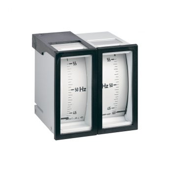
| FORMAT | 96x96 mm |
| VOLTAGE | 230…240 V |
| TYPE | Double frequencymeter |
| SCALE | 55…65 Hz |
| OPTIONS | without |
 Datasheet Datasheet |
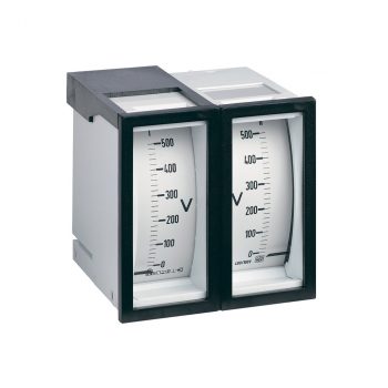
| INSERTION | on VT |
|---|---|
| FORMAT | 96x96 mm |
| VOLTAGE | 110 V 50…60 Hz = 100 % |
| TYPE | Double voltmeter |
| SCALE | 0…120 % |
| OPTIONS | without |
| Datasheet |
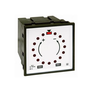
| INSERTION | on VT |
|---|---|
| FORMAT | 96x96 mm |
| VOLTAGE | 100…115 V 50…60 Hz |
| TYPE | LED synchroscope |
| OPTIONS | without |
| Datasheet |
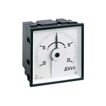
| INSERTION | on VT |
|---|---|
| FORMAT | 96x96 mm |
| VOLTAGE | 110 V 50…60 Hz |
| TYPE | Differenzial voltmeter |
| SCALE | 20…0…20 deltaVn% |
| OPTIONS | without |
| Datasheet |
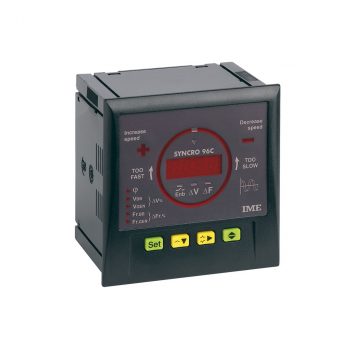
| AUX | 95...126 Vac |
|---|---|
| INSERTION | on VT |
| FORMAT | 96x96 mm |
| VOLTAGE | 30…150 V 35…80 Hz |
| TYPE | LED synchroscope with synchronizing contact |
| Datasheet |
| User Manual |
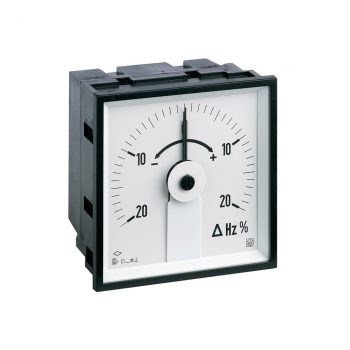
| INSERTION | on VT |
|---|---|
| FORMAT | 96x96 mm |
| VOLTAGE | 100 V 50 Hz |
| TYPE | Differential frequencymeter |
| SCALE | 20…0…20 deltaHzn% |
| OPTIONS | without |
| Datenblatt |
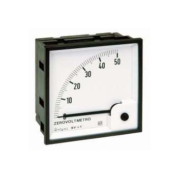
| INSERTION | on VT |
|---|---|
| FORMAT | 96x96 mm |
| VOLTAGE | 100 V 50…60 Hz |
| TYPE | Nullvoltmeter |
| SCALE | 0…50 V |
| OPTIONS | without |
| Datasheet |
