


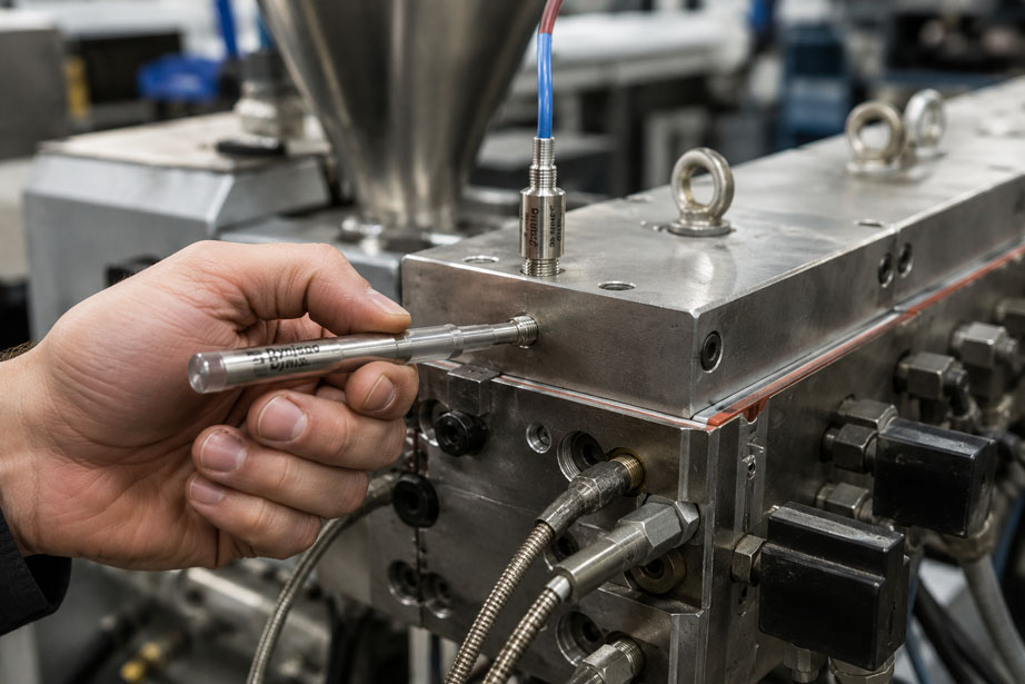
The melt pressure of an extruder can rise sharply within a short period of time during a process disturbance. A clogged screen pack, a blocked die, an obstructed melt channel or incorrect process control can cause the pressure in the extruder barrel to rise significantly above the normal operating range.
To protect the machine, a rupture disk or so-called burst plug is therefore installed.
But which rupture disk is the right one?
Simply selecting a burst pressure slightly above the normal process pressure is not sufficient.
For technically appropriate sizing, the following factors must be considered simultaneously:
- normal operating pressure,
- maximum process pressure spikes,
- permissible pressure of the machine components to be protected,
- rated burst pressure and burst tolerance,
- temperature at the installation point,
- material contact with the polymer melt,
- process connection and mounting hole,
- installation direction,
- dead volume or position of the rupture membrane,
- mechanical damage during installation or cleaning.
Particularly important:
The specified burst pressure of a rupture disk cannot be considered independently of temperature.
The mechanical properties of the membrane change with temperature. A rupture disk must therefore be selected for the actual process temperature range or for the reference temperature defined by the manufacturer.
A rupture disk must also not be confused with a pressure sensor.
A pressure sensor:
measures and monitors the process pressure
a rupture disk:
opens once at a defined overpressure and relieves the system
Both components complement each other but perform completely different functions.
Dynisco rupture disks and associated measuring instruments can be found at ICS Schneider under Measuring Instruments / Rupture Disks. An overview of additional solutions for plastics extrusion and melt pressure measurement can be found under Dynisco Products.
Table of Contents
- How does a rupture disk work on an extruder?
- Distinguishing between rupture disk, burst plug and burst screw
- Why does an extruder require overpressure protection?
- Distinguishing between operating pressure and burst pressure
- Selecting the correct burst pressure
- Considering burst tolerance during selection
- Why process temperature is critical
- Do not confuse normal pressure spikes with a fault condition
- Selecting a suitable installation location on the extruder
- Consider melt contact and dead volume
- Thread and mounting hole must match
- Do not reverse the installation direction
- Installation without damaging the membrane
- Clean the mounting hole correctly
- Identify mechanical damage
- What to do after the rupture disk has burst
- Identification and traceability
- Correctly combine a rupture disk and melt pressure sensor
- Typical fault patterns
- Systematic selection of a rupture disk
- Practical example: rupture disk opens during normal production
- Suitable ICS products
- Conclusion
- FAQ
How does a rupture disk work on an extruder?
A rupture disk is a passive pressure-relief device.
It contains a precisely designed metallic membrane.
As long as the process pressure remains within the intended range, the membrane stays closed.
When the defined burst pressure for the respective version is reached, the membrane intentionally ruptures and opens a relief path.
This allows the pressure in the protected system to be reduced quickly.
The basic sequence is:
normal operation → pressure increase → defined burst pressure reached → membrane opens → pressure relief
The rupture disk requires:
- no electrical power,
- no actuator,
- no control system,
- no moving valve mechanism.
It therefore provides a very direct form of overpressure protection.
Single-use protection function
A rupture disk is not an automatically reclosing pressure-control device.
After bursting, the protective membrane remains open.
The cause of the overpressure must be determined and the activated unit must then be replaced with a suitable new rupture disk.
An activated burst plug is therefore not a process event that can simply be reset.
Distinguishing between rupture disk, burst plug and burst screw
Different terms are used in plastics processing.
Rupture disk
The general term describes the actual pressure-relief element with a membrane designed to rupture at a defined condition.
Burst plug or burst screw
On extruders, the rupture disk is often designed as a complete screw-in assembly.
This may consist, for example, of:
- threaded body,
- process tip,
- welded rupture membrane.
Such assemblies are commonly referred to as burst plugs or burst screws.
Burst Plug
Dynisco uses the term:
Burst Plug
for these one-piece assemblies.
The advantage is that the rupture membrane is already permanently integrated with the process connection in a defined geometry.
Why does an extruder require overpressure protection?
During extrusion, polymer is conveyed at high temperature through the screw, barrel, screen changer and die.
The required melt pressure depends, among other things, on:
- material,
- viscosity,
- temperature,
- screw speed,
- throughput,
- die geometry,
- screen pack,
- flow resistance in the melt channel.
Under normal conditions, a certain process pressure is established.
However, a malfunction can cause this pressure to increase significantly.
Typical causes of overpressure
- clogged screen pack,
- blocked screen changer,
- clogged die,
- blocked die channel,
- melt temperature too low,
- significantly increased melt viscosity,
- excessive throughput,
- incorrect operation during start-up,
- unexpected material properties.
The pressure can rise faster than the operator can react.
A suitable rupture disk therefore provides an additional passive safety layer.
Distinguishing between operating pressure and burst pressure
The normal operating pressure is not automatically the correct burst pressure.
Assume that an extruder normally operates at:
poperating = 250 bar
During normal process fluctuations, short-term peaks of, for example:
300 bar
occur.
A rupture disk with a nominal burst pressure only slightly above 300 bar could then burst unnecessarily during normal process peaks.
If, on the other hand, the burst pressure is selected significantly too high, another machine component may be overloaded first in the event of a fault.
The following must therefore apply:
The burst pressure must be sufficiently above the permissible normal process range while remaining below the critical pressure limit of the system being protected.
Consider several pressure limits
At minimum, the following should be known during sizing:
- typical process pressure,
- maximum permissible operating pressure,
- normal pressure spikes,
- permissible pressure of the extruder barrel, adapter, screen changer and die,
- permissible pressure of connected sensors and components,
- burst tolerance of the intended rupture disk.
The burst pressure should therefore not be selected in isolation.
Selecting the correct burst pressure
The selection can be viewed in simplified form as a pressure window.
Below it is the normal process:
normal operation + permissible process pressure spikes
Above it is the limit of the machine to be protected:
maximum permissible pressure of the system
The rupture characteristic must lie between these two limits.
Simplified example
Assume:
- typical melt pressure: 220 bar,
- regular short-term peaks: 280 bar,
- critical permissible pressure limit of the component being considered: 500 bar.
A rupture disk must not simply be rated at:
280 bar
because regular peaks could otherwise cause unwanted bursting.
Likewise, a nominal burst pressure of:
> 500 bar
would clearly be unsuitable for the protective function if the component being protected reaches its permissible limit before that pressure.
The actual suitable nominal value must be determined based on the complete system, temperature and burst tolerance.
A general fixed percentage rule is not sufficient for all extruders.
Considering burst tolerance during selection
A rupture disk does not open mathematically at one exact pressure value.
For each design, the manufacturer specifies a burst tolerance or permissible burst-pressure range.
Assume that a rupture disk has:
Nominal burst pressure = 400 bar
and, as an example:
Burst tolerance = ±10 %
The theoretical tolerance range is then:
360…440 bar
This example illustrates an important point:
For system protection, the upper tolerance limit must be considered. To prevent unwanted bursting, the lower tolerance limit is equally important.
Lower limit case
The rupture disk must not open during a normal process condition.
Upper limit case
Even at the upper end of the permissible burst tolerance, the protected system must still remain adequately protected.
The nominal burst pressure alone is therefore not sufficient for a complete safety assessment.
Why process temperature is critical
A rupture membrane is a mechanical component.
The strength of its material depends on temperature.
The pressure at which the membrane ruptures is therefore also temperature-dependent.
For selection, the question should therefore not only be:
At what pressure should the rupture disk open?
but:
At what pressure and at what temperature should it open?
Consider melt temperature rather than ambient temperature
A common mistake would be to consider only the ambient temperature around the machine.
The rupture membrane is located at the process end of the assembly and is exposed to the hot extrusion process.
The relevant factor is therefore the thermal load at the actual installation point.
Temperature change after a material change
An extruder may initially process a polymer at:
220 °C
.
After a product change, the melt temperature increases to:
330 °C
Even if the pressure range and thread remain unchanged, it must be checked whether the rupture disk being used is still correctly specified for this temperature condition.
Do not confuse normal pressure spikes with a fault condition
Extrusion processes often have dynamic pressure fluctuations.
These may result, for example, from:
- changes in screw speed,
- screen changes,
- material batch changes,
- start-up processes,
- temperature changes,
- varying throughput.
During sizing, a distinction should therefore be made between:
normal process dynamics
and:
hazardous overpressure event
.
If the burst pressure is selected too close to the normal process maximum, unnecessary machine downtime may result.
Use pressure history
If melt pressure measurements are already available, the following should be evaluated before selecting the rupture disk:
- average pressure,
- maximum pressure during stable operation,
- pressure during start-up,
- pressure before a screen change,
- short-term peak values.
This provides a much better assessment of the actual process range than using only a single typical operating value.
Selecting a suitable installation location on the extruder
The rupture disk primarily protects the pressure zone to which it is directly connected hydraulically or through the melt.
The installation location should therefore correspond to the area that needs to be protected.
Typical positions include:
- on the extruder barrel,
- upstream of a screen changer,
- in an adapter block,
- in a melt channel.
Consider pressure loss within the system
Pressure is not identical at every point within an extrusion system.
A screen pack or narrow flow channel can, for example, cause a significant pressure drop.
A rupture disk installed downstream of such a restriction may therefore experience a different pressure from a machine section located upstream.
The location of the rupture disk must therefore correspond to the pressure zone that actually needs to be protected.
Consider melt contact and dead volume
Polymer melt can enter cavities and:
- remain there,
- thermally degrade,
- harden,
- carbonize,
- affect pressure transmission.
A suitable process geometry is therefore important.
Flush membrane
With a design in which the rupture membrane is flush with the process end, only a small additional dead volume is created.
This reduces areas where polymer can accumulate in front of the actual membrane.
Installed too deeply
If the membrane is positioned far behind the actual inner wall of the barrel, a longer melt channel may be created.
Material can accumulate or harden there.
Protruding too far into the process
Excessive insertion depth or incorrect installation geometry can also be problematic.
The following must therefore match the intended assembly:
- mounting-hole geometry,
- thread length,
- sealing surface,
- installation depth.
Thread and mounting hole must match
The correct burst pressure alone does not make a rupture disk suitable for an extruder.
The mechanical connection must also be correct.
The following should be checked, among other things:
- thread type,
- thread size,
- thread length,
- mounting-hole diameter,
- seating surface,
- installation depth.
Do not confuse similar threads
Different threads are used for high-pressure components.
A thread must therefore not be selected simply because the component appears to screw into the opening.
The thread and mounting hole must exactly match the geometry specified by the manufacturer.
Existing older installation
When replacing an older burst plug, at minimum the following should be recorded:
- manufacturer,
- type,
- engraved marking,
- nominal burst pressure,
- temperature specification,
- thread,
- installation length.
A replacement component should not be selected solely on the basis of its outside diameter.
Do not reverse the installation direction
The rupture membrane must be located on the intended process side.
The pressure load must therefore act on the membrane in the direction intended by the design.
With a screw-in burst plug, the geometry is generally clear:
Process / polymer melt → rupture membrane → burst plug body → relief side
An incorrect installation can:
- alter the burst characteristic,
- obstruct pressure relief,
- render the protection ineffective.
Also consider the relief path
After bursting, hot process medium and pressure are released.
The relief side of the installation must therefore also be designed safely.
The relief path must not be:
- intentionally closed,
- blocked by an unsuitable cover,
- directed toward personnel.
The specific design must comply with the machine and safety concept.
Installation without damaging the membrane
The rupture membrane is deliberately designed to fail at a defined load.
Mechanical damage can therefore alter its characteristics.
Potentially problematic conditions include:
- impact against the membrane,
- contact with tools,
- scratches,
- denting,
- improper cleaning,
- dropping the assembly.
Do not mechanically clean the membrane
Polymer residues must not be removed from the rupture membrane using:
- screwdrivers,
- drills,
- wire brushes,
- grinding tools.
Even slight mechanical pre-damage can affect the subsequent bursting behavior.
Observe the tightening torque
The tightening torque is also part of the installation specification.
Insufficient torque can result in:
- leakage,
- loose seating.
Excessive torque can unnecessarily stress:
- threads,
- sealing surfaces,
- component geometry.
Only the installation procedure specified for the particular product series should therefore be used.
Clean the mounting hole correctly
A contaminated mounting hole is one of the typical problems associated with sensors and burst plugs on extruders.
The mounting hole may contain:
- hardened polymer residues,
- carbonized material,
- burrs,
- damaged threads.
If a new rupture disk is screwed in against such residues, it may:
- not seat correctly,
- be mechanically stressed,
- be damaged,
- reach an incorrect installation depth.
Clean the mounting hole, not the membrane
An important distinction:
The sensitive rupture membrane should not be mechanically worked on; instead, the mounting hole must be properly prepared before installation.
Suitable cleaning and inspection tools are available for the respective mounting holes.
Identify mechanical damage
A rupture disk with visible mechanical damage should not be installed.
Before installation, the following should be inspected in particular:
- membrane surface,
- process tip,
- thread,
- sealing surface,
- identification markings.
Typical abnormalities
- dent in the membrane,
- scratches,
- bent tip,
- damaged thread,
- corrosion,
- missing or illegible markings.
A visibly damaged rupture disk must not be judged acceptable simply because it “still appears leak-tight.”
The decisive property is its reproducible bursting behavior.
What to do after the rupture disk has burst
If a rupture disk has burst, the component should not simply be replaced.
The rupture indicates that the process has reached a critical condition.
The cause must therefore be investigated before restarting the system.
Possible causes
- clogged screen,
- blocked die channel,
- melt temperature too low,
- excessive throughput,
- screen changer malfunction,
- incorrect machine configuration,
- unsuitable burst-pressure sizing.
Systematic procedure
- Stop the extruder safely.
- Depressurize the process.
- Determine the cause of the overpressure.
- Check the relief channel.
- Inspect and clean the mounting hole.
- Check the machine parameters.
- Identify the activated rupture disk.
- Select a replacement with identical or technically approved specifications.
- Install the new assembly according to the installation instructions.
- Monitor the process especially carefully during restart.
Identification and traceability
For a safety-relevant component, it should be possible to determine later which version was installed.
The following should be documented, for example:
- manufacturer,
- type or series,
- part number or order number,
- nominal burst pressure,
- associated temperature specification,
- thread,
- installation date,
- installation position.
Ordering based only on appearance is risky
Two burst plugs may look almost identical externally while still having:
- different burst pressures,
- different temperature characteristics,
- different installation lengths,
- different threads.
A replacement part should therefore be selected based on its complete technical specification.
Correctly combine a rupture disk and melt pressure sensor
A rupture disk does not replace continuous pressure measurement.
Likewise, a melt pressure sensor does not automatically replace passive emergency pressure relief.
The functions are different.
| Component | Function |
|---|---|
| Melt pressure sensor | Continuous measurement of process pressure |
| Display / machine control | Monitoring, alarming and process control |
| Rupture disk / burst plug | Passive single-use pressure relief in the event of critical overpressure |
Early detection using a pressure sensor
A melt pressure sensor can, for example, detect that the pressure is gradually increasing:
250 bar → 280 bar → 320 bar → 350 bar
The machine control system can then:
- trigger an alarm,
- reduce throughput,
- shut down the machine.
The rupture disk remains in place as an independent mechanical protection layer for the intended overpressure event.
Do not select burst pressure based on the sensor measuring range
The measuring range of the installed pressure sensor and the burst pressure of the rupture disk are two different parameters.
For example, a:
0…700 bar melt pressure sensor
does not automatically mean that:
700 bar
is the appropriate burst pressure for the machine.
The decisive factor is the permissible pressure level of the entire system being protected.
Typical fault patterns with rupture disks on extruders
| Observation | Possible cause | Recommended check |
|---|---|---|
| Rupture disk regularly opens during normal operation | Burst pressure too low or process pressure spikes too high | Check pressure history, temperature and burst specification |
| Rupture disk opens immediately during start-up | High start-up pressure spike, temperature too low or incorrect sizing | Check start-up profile and actual melt pressure |
| New rupture disk opens significantly earlier than expected | Mechanical damage or incorrect temperature rating | Check membrane, installation and type identification |
| Incorrect burst pressure despite identical thread | Incorrect version installed | Compare complete part identification |
| Polymer accumulates in front of the rupture membrane | Dead volume or unsuitable installation geometry | Check mounting hole and installation depth |
| Burst plug is difficult to screw in | Polymer residues or damaged thread | Inspect mounting hole with suitable tools |
| Membrane has a dent or scratches | Installation or transport damage | Do not install the component; verify the specification |
| Extruder reaches critical pressure but rupture disk does not respond as expected | Incorrect burst pressure, temperature, installation location or relief path | Professionally inspect the complete protective function |
| No significant pressure reduction after bursting | Relief path obstructed or process channel blocked | Check relief path and installation position |
| Operator does not immediately notice the burst event | No burst indication available | Consider a version with separate burst indication |
| Rupture disk no longer performs reliably after a product change | New process or melt temperature | Reassess temperature specification |
| Repeatedly different burst events under similar process conditions | Process dynamics, installation or specification not reproducible | Document pressure/temperature history and installation condition |
Systematic selection of a rupture disk
The following procedure is recommended for a new application or replacement:
- Determine the application: Extruder, screen changer, adapter, die or another process section?
- Define the installation position: Which pressure zone needs to be protected?
- Record normal process pressure: Document the typical operating value.
- Record process pressure spikes: Consider start-up, screen changes and maximum production conditions.
- Determine permissible system pressure: Consider the weakest relevant component.
- Determine temperature: Consider the actual melt or membrane temperature at the installation point.
- Consider burst tolerance: Evaluate the lower and upper limits of the possible opening pressure.
- Select nominal burst pressure: Define a suitable pressure window between normal operation and critical system loading.
- Determine the process connection: Identify the thread and mounting hole exactly.
- Check installation length: Verify the membrane position relative to the melt channel.
- Check material: Consider suitability for temperature and process medium.
- Evaluate the relief path: Ensure effective and safe pressure relief is possible when the disk bursts.
- Check burst indication: If automatic notification is required, select a suitable version.
- Document identification: Record type, burst pressure, temperature and installation position.
- Define installation requirements: Observe the manufacturer’s tightening torque and installation instructions.
- Perform a plausibility check after commissioning: Monitor the pressure profile during normal operation.
Practical example: rupture disk opens during normal production
An extruder has been operating with a particular polymer for several years.
The typical melt pressure is:
p ≈ 240 bar
The existing rupture disk has operated reliably in the past.
Step 1: new material
The processed polymer is changed.
At the existing process settings, the new material has a higher melt viscosity.
Step 2: pressure increases
During production, values of:
300…330 bar
are now measured regularly.
Even higher values occur briefly during start-up.
Step 3: rupture disk opens
After several production runs, the rupture disk activates during start-up.
The machine is stopped.
The initial assumption is:
rupture disk defective
Step 4: evaluate pressure history
However, the measurement data from the melt pressure sensor shows that the new process now operates continuously much closer to the rupture range.
The melt temperature has also been changed compared with the previous process.
Step 5: evaluate the complete protection chain
The following are now checked:
- maximum permissible pressure of the extruder,
- screen changer,
- die,
- melt pressure sensor,
- burst pressure of the existing rupture disk,
- burst tolerance,
- temperature specification.
Step 6: do not simply install a rupture disk with a higher burst pressure
An obvious but potentially incorrect reaction would be:
“Then we will simply use a rupture disk with a higher pressure rating.”
However, this could exceed the protection limit of the machine.
It must therefore first be determined whether the process pressure can be reduced or whether the complete system is actually designed for a higher pressure.
Result
In this example, the rupture event was not necessarily caused by a defective rupture disk.
It indicated that the process had changed compared with the original design conditions.
The correct burst pressure can therefore only be assessed together with the actual process pressure, pressure spikes, temperature and permissible system pressure.
Suitable ICS products for overpressure protection on extruders
Dynisco BP420 – burst plug for plastics extrusion systems
The Dynisco BP420 Series available from ICS was specifically developed for pressure relief in plastics extrusion systems.
The one-piece assembly consists of:
- a stainless-steel body,
- a welded Inconel rupture disk.
The rupture membrane is located flush with the process end of the assembly.
This avoids an unnecessarily deep cavity directly in front of the membrane where polymer melt could accumulate.
Different burst-pressure versions are available for the series.
Depending on the version, the current specification covers burst-pressure ranges of:
1,000…15,000 psi
and the assembly is designed for high melt temperatures.
Burst pressure and temperature must be specified together when selecting the correct version.
Further information can be found under Dynisco BP420 at ICS Schneider.
Dynisco BP520 – burst plug with Pop-Top burst indication
The Dynisco BP520 Series combines passive pressure relief with a mechanical burst indication.
The basic assembly also features:
- a threaded body,
- a welded rupture membrane,
- a one-piece high-temperature design.
In addition, this version features a Pop-Top system.
When the rupture disk bursts, the indicator mechanism opens and can break a burst-indication wire.
This allows an activated burst event to be integrated into machine or control-system monitoring.
Depending on the version, the current series is available with burst ratings of:
750…15,000 psig
.
The specified burst tolerance is:
±10 %
of the specified burst rating.
Further information can be found under Dynisco BP520 at ICS Schneider.
BP420 or BP520?
| Requirement | Suitable series |
|---|---|
| Passive emergency pressure relief on the extruder | BP420 |
| Flush rupture membrane at the process end | BP420 |
| Burst event should additionally be detected electrically or by the control system | BP520 with Pop-Top burst indication |
| Customer-specific installation situation on the extruder barrel | BP520 depending on version |
| Continuous pressure measurement required | Additional suitable Dynisco melt pressure sensor |
Melt pressure measurement as a supplement
For continuous monitoring of extruder pressure, ICS also offers Dynisco melt pressure sensors and transmitters.
This allows a concept consisting of:
continuous pressure measurement + process alarm + machine shutdown + passive rupture relief
to be implemented.
The protective functions actually required depend on the respective machine and its safety design.
Further Dynisco products can be found under Dynisco Products at ICS Schneider.
Conclusion
A rupture disk on an extruder is a relatively small component with a critical safety function.
Its selection must therefore not be based solely on the thread or a single pressure value.
The following must be considered together:
- normal melt pressure,
- maximum process pressure spikes,
- permissible system pressure,
- nominal burst pressure,
- burst tolerance,
- melt temperature,
- installation position,
- thread and mounting-hole geometry,
- installation length,
- relief path.
Temperature dependence is particularly important.
A rupture disk does not simply have one universal opening pressure regardless of its thermal condition.
Burst pressure and temperature must therefore always be considered together.
Burst tolerance must also be included in the sizing process.
Not only the nominal burst pressure but also both the possible lower and upper burst limits must suit the machine.
The lower limit must not fall within normal process pressure spikes.
The upper limit must not compromise safe protection of the machine.
Correct installation is equally important.
The rupture membrane must not be:
- scratched,
- dented,
- worked on with tools.
The mounting hole must be clean and geometrically correct.
After a burst event, a new rupture disk should also not simply be screwed in without further investigation.
The event indicates an overpressure condition.
The cause must therefore be investigated.
Finally, the rupture disk should be considered as part of an overall protection concept.
A melt pressure sensor can detect increasing pressure at an early stage and inform the machine control system.
The rupture disk, on the other hand, provides passive, single-use pressure relief.
For practical applications:
Record process pressure → evaluate pressure spikes → determine maximum permissible system pressure → define temperature at the installation point → consider burst tolerance → select suitable nominal burst pressure → check thread and mounting hole → verify membrane position and relief path → install rupture disk without damage → document identification → after a burst event, analyze the cause and replace the unit.
FAQ: Rupture Disks and Burst Plugs for Extruders
What is a rupture disk on an extruder?
A rupture disk is a passive overpressure protection device. Its membrane opens at a defined pressure and temperature condition, thereby allowing pressure relief.
What is a burst plug?
A burst plug is a complete screw-in assembly consisting of a threaded body and an integrated rupture membrane. Such designs are particularly common on plastics extruders.
What is the difference between a rupture disk and a burst screw?
The rupture disk is the actual pressure-dependent membrane element that opens. In a burst screw or burst plug, this membrane is already permanently integrated into a screw-in body.
How do I select the correct burst pressure?
The burst pressure must be above normal operating and process pressure spikes while also being selected so that the machine components being protected are not exposed to excessive pressure. Temperature and burst tolerance must also be considered.
Should the burst pressure simply be 10% above the operating pressure?
No. A general fixed percentage rule is not suitable for every extruder application. Normal pressure, process pressure spikes, temperature, burst tolerance and permissible system pressure must be evaluated together.
What does burst tolerance mean?
Burst tolerance describes the range within which a rupture disk can actually open around its specified nominal burst pressure.
Why must burst tolerance be considered?
The lower limit must not fall within the normal process range. At the same time, the upper limit must still provide adequate protection for the machine.
Is burst pressure temperature-dependent?
Yes. The mechanical properties of the rupture membrane change with temperature. The specified temperature or temperature range is therefore part of the sizing process.
Which temperature do I need to specify?
The relevant value is the actual thermal load on the rupture membrane at the installation point. For extruders, the process or melt temperature in particular must therefore be considered.
What happens if the process temperature is changed later?
It should then be checked whether the existing rupture disk is still suitable for the new temperature condition and the required burst pressure.
Why does my rupture disk open during normal operation?
Possible causes include a burst pressure selected too low, higher process pressure spikes than expected, a changed temperature, mechanical pre-damage or an incorrect version.
Why does the pressure at the extruder suddenly rise?
Possible causes include a clogged screen pack, a blocked melt channel, melt temperature that is too low, excessive throughput or a problem with the screen changer or die.
Can I simply install a rupture disk with a higher burst pressure?
Not without checking the pressure resistance of the system. A higher burst pressure may cause other machine components to be exposed to excessive pressure before the rupture disk activates.
Where should a rupture disk be installed on an extruder?
The suitable installation location depends on the pressure zone that needs to be protected. The melt channel, pressure losses and machine design must be considered in particular.
Why is low dead volume important?
Polymer melt can remain in dead spaces, thermally degrade or harden. A suitable flush process geometry reduces such areas.
What happens if the mounting hole is contaminated?
Polymer residues or damaged threads can prevent the burst plug from seating correctly and can cause mechanical damage or an incorrect installation position.
Can I clean a rupture membrane with a wire brush?
No. The membrane must not be mechanically damaged or abraded. The mounting hole should be cleaned using tools suitable for this purpose.
Can a small scratch affect its function?
Mechanical pre-damage can alter the defined bursting behavior of the membrane. Damaged components should therefore not be installed.
What happens after the rupture disk bursts?
The membrane remains open. The process cause must be investigated and the activated assembly must be replaced with a technically suitable new burst plug.
Can an activated rupture disk be reset?
No. A rupture disk is a single-use protective device.
Must the cause be investigated after every burst event?
Yes. A burst event indicates that a critical pressure condition was reached or that the sizing or process needs to be reviewed.
Is a rupture disk the same as a safety valve?
No. A rupture disk opens by intentional failure of a membrane and remains open afterwards. A safety valve has a mechanical opening and closing mechanism.
Is a rupture disk the same as a pressure sensor?
No. A pressure sensor continuously measures the process pressure. A rupture disk is a passive pressure-relief device and normally does not provide a continuous measurement value.
Do I also need a melt pressure sensor?
Continuous melt pressure measurement is often useful for process monitoring. The sensor can detect pressure increases while the rupture disk provides a separate passive safety function.
Can the measuring range of the pressure sensor be used as the burst pressure?
No. The sensor measuring range and required burst pressure are different parameters. The protection limit must be determined based on the machine being protected.
What is the Dynisco BP420?
The BP420 is a screw-in burst plug for plastics extrusion systems with a welded Inconel rupture disk at the process end.
What burst-pressure ranges does the BP420 offer?
Depending on the version, the currently available series covers burst-pressure ranges of approximately 1,000 to 15,000 psi.
For which temperatures is the BP420 designed?
The series is designed for high-temperature applications in plastics extrusion and is currently specified for melt temperatures up to approximately 425 °C. The specific version must match the actual application.
What is the difference between the BP420 and BP520?
The BP520 supplements the rupture protection function with a Pop-Top burst indication that can be used to signal a burst event to a control system.
What burst-pressure range does the BP520 offer?
Depending on the version, current burst ratings of approximately 750 to 15,000 psig are available.
What is the burst tolerance of the BP520?
Dynisco specifies a burst tolerance of ±10% for the current BP520 series.
What information do I need for an inquiry?
At minimum, the normal process pressure, maximum pressure, required burst pressure, process temperature, existing thread, mounting hole, installation length and designation of the previously used rupture disk are helpful.
What additional information should be provided for a replacement part?
Ideally, provide the manufacturer, complete type designation, engraved burst pressure, temperature specification, thread and photos of the existing assembly or installation point.
Where can I find Dynisco rupture disks at ICS Schneider?
An overview can be found under Measuring Instruments / Rupture Disks at ICS Schneider.
Where can I find additional Dynisco products?
An overview can be found under Dynisco Products at ICS Schneider.