


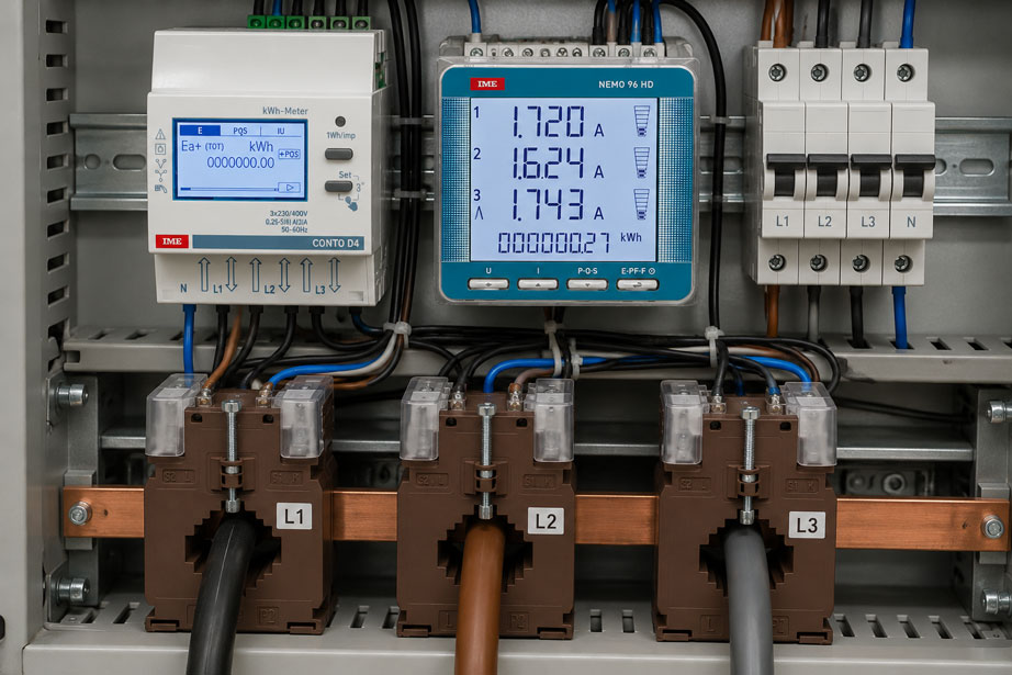
A three-phase energy meter is connected via three external current transformers. The currents shown on the display initially appear plausible, yet the meter indicates an unusually poor power factor, individual phases show negative active power, or the accumulated energy is significantly lower than expected.
Is the energy meter defective?
Often not.
In energy measurements using current transformers, wiring and configuration errors are among the most common causes of apparently incorrect measured values.
Particularly critical are:
- reversed current transformer direction,
- swapped secondary terminals S1/S2 or k/l,
- current transformers from the wrong phase connected to the meter input,
- incorrect assignment between current and voltage phases,
- incorrect current transformer ratio configured in the energy meter,
- confusion between 1 A and 5 A secondary current,
- unsuitable or excessively high burden in the current transformer circuit.
The fundamental problem is simple:
An energy meter does not only need the correct current magnitude. It must also know which voltage this current belongs to and in which direction or phase relationship it flows.
For three-phase energy measurement, the measurement chain is therefore:
Conductors L1/L2/L3 → current transformers → secondary wiring → current channels I1/I2/I3 → voltages U1/U2/U3 → phase angle → power calculation → energy metering
A single error anywhere in this chain can result in current values appearing correct while the calculated power and energy are incorrect.
Measuring instruments for these applications can be found at ICS Schneider under Energy Management. Suitable instrument transformers can be found under Current and Voltage Transformers.
Table of Contents
- Why current transformers are used for energy meters
- Correctly understanding P1/P2, S1/S2 and K/L, k/l
- Why current transformer polarity is important
- Why an incorrectly polarized current transformer causes negative power
- Correctly assign current and voltage phases
- Distinguish between phase sequence and phase assignment
- Correctly configure the current transformer ratio
- Do not confuse 1 A and 5 A secondary current
- Consider burden and cable length
- Never leave a current transformer secondary circuit unintentionally open
- How the energy meter calculates power from current and voltage
- Incorrect power factor as a diagnostic indication
- Effects on energy and consumption values
- Plausibility check after commissioning
- Typical fault patterns
- Systematic troubleshooting
- Practical example: energy meter shows only one third of the expected power
- Document wiring and configuration
- Suitable ICS products
- Conclusion
- FAQ
Why current transformers are used for energy meters
Many energy meters cannot directly measure high operating currents.
A current transformer therefore proportionally reduces the primary current to a standardized secondary current.
Typical versions include, for example:
100 A / 5 A
400 A / 5 A
600 A / 1 A
1000 A / 1 A
With a current transformer:
400 A / 5 A
400 A primary current ideally corresponds to 5 A secondary current.
At half the primary current:
Iprim = 200 A
the secondary current is correspondingly approximately:
Isec = 2.5 A
The energy meter measures the secondary current and converts it back to the primary-side value using the configured transformer ratio.
However, the current transformer does not only transfer the magnitude of the current.
Its polarity and phase relationship are also essential for power calculation.
Correctly understanding P1/P2, S1/S2 and K/L, k/l
Different terminal designations are used for current transformers.
Common designations include:
| IEC-oriented designation | Traditional designation | Meaning |
|---|---|---|
| P1 | K | Primary side with defined polarity assignment |
| P2 | L | Opposite primary side |
| S1 | k | Secondary terminal assigned to P1/K |
| S2 | l | Secondary terminal assigned to P2/L |
With a window-type current transformer, the primary winding is often the conductor or busbar routed through the opening.
The primary direction may then be indicated by:
- P1/P2,
- K/L,
- a direction arrow,
- or a corresponding marking on the housing.
The specific marking used depends on the manufacturer and current transformer.
The terminal markings shown in the respective data sheet or on the nameplate are therefore always decisive.
Typical energy flow
For consumption measurement, the intended installation direction may, for example, be:
Grid → P1/K → current transformer → P2/L → load
On the secondary side, the corresponding defined assignment is:
S1/k → current measuring input of the meter → S2/l
If the current transformer is mechanically rotated by 180° or S1 and S2 are swapped, the polarity of the current signal changes.
Why current transformer polarity is important
For a simple current indication, the direction initially appears to be irrelevant.
An energy meter may, for example, still display:
I = 120 A
even though the associated current transformer is connected with reversed polarity.
For power calculation, however, the meter additionally requires the phase relationship between voltage and current.
In simplified form, the following applies to one phase:
P = U · I · cos φ
where:
- P = active power,
- U = voltage,
- I = current,
- φ = phase angle between voltage and current.
If the current polarity is reversed, the current phasor is electrically shifted by:
180°
An angle of, for example:
φ = 20°
may therefore appear to the meter as approximately:
φ = 200°
or the corresponding equivalent angular representation.
The active-power component consequently changes sign.
Why an incorrectly polarized current transformer causes negative power
A common observation during commissioning is:
Current positive and plausible → active power negative
This is an important diagnostic indication.
In a system that is clearly drawing electrical energy from the grid, negative power values may, for example, be caused by:
- reversed installation direction of the current transformer,
- swapped S1/S2 or k/l terminals,
- incorrect current/voltage phase assignment,
- actual power export, for example from a PV system or generator.
Negative power should therefore not automatically be “corrected” by changing the configuration.
The first question must be:
Is the negative power physically real, or is it caused by a wiring error?
All three current transformers installed in the wrong direction
If all three current transformers in a consumer installation are polarized in the opposite direction, the following may occur:
- all three phases show negative active power,
- total active power is negative,
- import and export appear to be reversed.
The current magnitude itself may still appear completely plausible.
Only one current transformer installed in the wrong direction
If only one current transformer is reversed, the fault can be significantly more difficult to detect.
With an approximately balanced load and a power factor close to 1, each phase provides approximately the same active-power contribution:
PL1 ≈ PL2 ≈ PL3
If two phases are correct and one phase is reversed, the simplified result is:
Ptotal ≈ P + P - P = P
instead of:
Ptotal,correct ≈ 3P
The energy meter may therefore indicate only approximately one third of the actual active power.
The exact behavior depends on the load, measuring instrument and sign convention, but this fault pattern is typical.
Correctly assign current and voltage phases
With a three-phase energy meter, the current and voltage of the same phase must be evaluated together.
The assignment should, for example, be:
| Voltage | Associated current transformer | Current input |
|---|---|---|
| U L1 | CT L1 | I1 |
| U L2 | CT L2 | I2 |
| U L3 | CT L3 | I3 |
If, for example, the current from L1 is evaluated together with the voltage from L2, the energy meter may still show plausible individual values for:
- voltage,
- current,
- frequency,
but the angle between voltage and current is incorrect.
This particularly causes incorrect calculations of:
- active power,
- reactive power,
- power factor,
- active energy,
- reactive energy.
A 120° phase displacement can look like power export
In a balanced three-phase system, the phases are separated by approximately 120°.
Assume that a nearly resistive load on L1 has:
φ ≈ 0°
If the current from L1 is mistakenly evaluated against the voltage from L2, an angle in the range of:
±120°
results.
Since:
cos 120° = -0.5
the calculated active power may even become negative.
The energy meter then appears to detect power export even though the installation is actually consuming energy.
Distinguish between phase sequence and phase assignment
The terms phase sequence and phase assignment should not be confused.
Phase sequence
The phase sequence describes the order of the three-phase system, for example:
L1 → L2 → L3
or the reverse sequence.
Phase assignment
For power measurement, it is additionally essential that each current channel is assigned to the correct voltage.
For example:
U1 ↔ I1
U2 ↔ I2
U3 ↔ I3
Swapping both together may remain unnoticed
If, for example, L2 and L3 are swapped both at the voltage inputs and at the current transformers, many power values may still appear plausible.
However, the indicated phase sequence or phase designation may be incorrect.
If only the voltage side or only the current side is swapped, the U and I pairing is no longer correct.
This typically results in significant errors in power and power factor.
Correctly configure the current transformer ratio
The energy meter measures only the secondary current of the current transformer.
For the instrument to display the actual primary current and the resulting energy, the current transformer ratio must be configured correctly.
The CT factor is calculated as:
kCT = Iprim,n / Isec,n
Example 400/5 A
For a current transformer:
400 A / 5 A
the factor is:
kCT = 400 / 5 = 80
If the energy meter measures on the secondary side:
2.5 A
this corresponds on the primary side to:
2.5 A · 80 = 200 A
Example 600/1 A
For:
600 A / 1 A
the factor is:
kCT = 600
A secondary current of:
0.5 A
therefore corresponds to:
300 A primary
Some energy meters do not ask directly for the factor
Depending on the measuring instrument, the following may instead be entered separately:
- CT primary = 400 A,
- CT secondary = 5 A.
The instrument then calculates the transformation ratio internally.
Other instruments use a direct multiplication factor.
The important point is:
The current transformer nameplate and the energy meter configuration must match exactly.
Do not confuse 1 A and 5 A secondary current
Conventional measuring current transformers often have a rated secondary current of:
1 A
or:
5 A
The energy meter must be suitable for the secondary current used or be configured accordingly.
Example
Installed current transformer:
500 A / 5 A
correct transformation factor:
500 / 5 = 100
If a 1-A configuration is accidentally entered in the energy meter as:
500 A / 1 A
the calculated result is:
k = 500
instead of:
k = 100
The scaling therefore differs by a factor of:
5
It must, of course, also be ensured that the actual current input of the measuring instrument is designed for the connected secondary current.
Why are 1-A current transformers used?
One advantage of 1-A secondary circuits becomes apparent with longer cable runs.
The loss in a resistive secondary cable can be approximated by:
Pcable = Isec² · Rloop
With the same cable resistance:
5² / 1² = 25
A 5-A secondary circuit therefore theoretically produces 25 times the power loss or VA burden in the same line impedance compared with a 1-A secondary circuit.
1-A current transformers can therefore be particularly advantageous for greater distances between the current transformer and the measuring instrument.
Consider burden and cable length
A current transformer has a permissible or specified burden.
The connected total burden does not consist only of the energy meter input.
The following must also be taken into account:
- measuring instrument input,
- secondary cables,
- test terminals,
- plug contacts,
- additional measuring instruments connected in series.
In simplified form:
Stotal ≈ Sinstrument + Scable + Sadditional components
An excessive burden can load the current transformer more heavily and result in additional ratio and phase errors.
The phase error is particularly relevant for accurate power and energy measurement because the energy meter uses the angle between current and voltage to calculate power.
Accuracy class alone is not sufficient
A class 0.5 current transformer does not automatically result in an overall measurement of class 0.5.
The measurement chain also includes:
- energy meter,
- CT burden,
- cables,
- connection quality,
- configuration,
- voltage measurement.
The overall accuracy must therefore be considered across the complete measurement chain.
Never leave a current transformer secondary circuit unintentionally open
For a conventional inductive current transformer, one particularly important safety rule applies:
A current transformer secondary circuit must not be operated unintentionally open while primary current is flowing.
If, for example, the energy meter is removed while current continues to flow through the primary conductor, the current transformer’s secondary circuit must not simply be disconnected and left open.
Dangerously high voltages can occur across an open secondary circuit.
The current transformer may also be subjected to significant thermal and magnetic stress.
Use short-circuit terminals or test-disconnect terminals
Suitable test or short-circuit terminals are therefore used in measuring installations with current transformers.
This makes it possible, for example, to:
- safely short-circuit the current transformer secondary circuit,
- then disconnect the energy meter,
- test or replace the meter,
- and afterwards restore the measuring circuit in a controlled manner.
The specific switching procedure depends on the terminal technology used and the company’s safety procedures.
Work on these measuring circuits must only be carried out by appropriately qualified personnel.
How the energy meter calculates power from current and voltage
An energy meter does not determine power from current alone.
For each phase, both voltage and current, including their phase relationship over time, are required.
In simplified form, the following applies to each phase:
P1 = U1 · I1 · cos φ1
P2 = U2 · I2 · cos φ2
P3 = U3 · I3 · cos φ3
The total active power is:
Ptotal = P1 + P2 + P3
For a balanced three-phase load, the following simplified expression can also be used:
P = √3 · ULL · I · cos φ
This relationship demonstrates why a correctly measured current alone is not sufficient.
If the angular assignment is incorrect, the calculated active power will also be incorrect.
Incorrect power factor as a diagnostic indication
An unexpected power factor is often one of the best indications of incorrect current/voltage assignment.
Assume that for a resistive heater or another largely resistive load the expected value is:
PF ≈ 1
However, the energy meter indicates on one phase:
PF ≈ -0.5
or another obviously implausible value.
The load should not immediately be suspected.
The following should first be checked:
- CT polarity,
- assignment U1/I1, U2/I2 and U3/I3,
- phase sequence,
- voltage connections,
- current transformer connections.
Do not draw conclusions too quickly with motors
For motors, transformers, frequency converters and other more complex loads, the actual power factor may differ significantly from 1.
A plausibility check must therefore always match the actual load.
A useful comparison is:
expected system behavior ↔ indicated current ↔ active power ↔ reactive power ↔ power factor
Effects on energy and consumption values
Energy is obtained from power over time.
In simplified form:
E = ∫ P(t) dt
A permanently incorrect power value therefore directly results in incorrect energy metering.
Depending on the measuring instrument and configuration, wiring errors may, for example, result in:
- too little consumption being counted,
- consumption appearing as export,
- positive and negative energy being accumulated incorrectly in separate registers,
- individual phases offsetting one another,
- implausible reactive energy values.
This is particularly problematic for:
- cost-center metering,
- submetering,
- energy management systems,
- PV systems,
- battery storage systems,
- charging infrastructure,
- machine energy-consumption measurement.
Plausibility check after commissioning
After connecting an energy meter, it is not sufficient merely to verify that numbers appear on the display.
A structured plausibility check can immediately detect many wiring errors.
1. Check voltages
Check:
- U L1-N,
- U L2-N,
- U L3-N,
- line-to-line voltages where applicable.
2. Check currents
Compare the indicated currents with:
- the system load,
- nameplate values,
- a suitable reference measurement where applicable.
3. Check the CT factor
Check the nameplate of each current transformer.
For example:
L1 = 400/5 A
L2 = 400/5 A
L3 = 400/5 A
and compare this with the energy meter configuration.
4. Check power per phase
In a consumer installation, the sign convention should be plausible.
For example, the following would be suspicious:
L1: +18 kW
L2: -17 kW
L3: +19 kW
for a balanced three-phase load consuming power.
5. Check the power factor
With similar loads on all three phases, two phases should not, for example, indicate:
PF = 0.94
while the third indicates:
PF = -0.48
unless the system behavior provides a technical explanation for this.
6. Check the phase sequence
If the measuring instrument provides phase-sequence or wiring diagnostics, these should also be checked.
7. Observe the energy counting direction
With a load that is clearly consuming power, verify that the expected import or consumption register increases.
8. Deliberately change the load
If operationally possible, a known load can be switched on or off.
The associated current and power value should then respond on the correct phase.
This is a very effective method of checking the phase assignment.
Typical fault patterns in current-transformer energy measurements
| Observation | Possible cause | Recommended check |
|---|---|---|
| All currents plausible, total active power negative | All current transformers reversed or actual power export | Check installation direction, S1/S2 and direction of energy flow |
| Only one phase shows negative active power | One current transformer has reversed polarity | Check P1/P2 or S1/S2 of the affected phase |
| Current values correct, power factor completely implausible | Current and voltage from different phases assigned to each other | Check U1/I1, U2/I2 and U3/I3 |
| One phase shows approximately correct current but negative power | CT polarity or phase assignment incorrect | Check phasor/power indication for each phase |
| All values approximately a factor of 5 too high | Incorrect 1-A/5-A configuration or CT factor | Compare CT nameplate and meter configuration |
| All values consistently incorrect by the same factor | Incorrect transformer ratio | Check primary/secondary values in the meter |
| Energy significantly too low, one phase negative | One current transformer has reversed polarity | Check power per phase rather than only total power |
| Currents L2 and L3 swapped | Secondary wiring swapped | Trace CT L2/L3 to the meter inputs |
| Phase-sequence error while power values still appear partly plausible | Voltage and current channels swapped together | Check phase designation and phase rotation |
| Power suddenly incorrect after replacing the meter | CT secondary current or transformer factor not transferred | Compare old and new device configuration |
| Measurement deviation increases at high load | CT burden, saturation or unsuitable current transformer | Check burden, class, rated current and sizing |
| Measured values fluctuate after work on terminals | Loose secondary connection | Check terminals according to the work procedure |
| Energy is counted as export instead of import | Measurement direction reversed or actual power export | Verify power flow and CT direction |
| Meter shows almost no total active power despite load | Several phase contributions are cancelling one another | Check individual phase power and current/voltage assignment |
Systematic troubleshooting of incorrect energy meter values
A structured procedure prevents wiring errors from merely being concealed by subsequent configuration changes.
- Clarify the system condition: Is energy actually being imported or exported?
- Check the meter type: Compare the network configuration and wiring method with the application.
- Identify the current transformers: Document manufacturer, type and transformation ratio.
- Check secondary current: 1 A or 5 A?
- Check meter configuration: Compare the primary and secondary values with the current transformer.
- Identify CT L1: Ensure that it is actually installed around conductor L1.
- Identify CT L2: Check the assignment.
- Identify CT L3: Check the assignment.
- Check primary polarity: Verify P1/P2 or K/L and the direction arrow.
- Check secondary polarity: Trace S1/S2 or k/l through to the meter.
- Check voltage assignment: Verify U1, U2 and U3.
- Check current/voltage pairing: Ensure U1/I1, U2/I2 and U3/I3 are paired correctly.
- Check phase sequence: Verify phase rotation or the device indication.
- Check current plausibility: Compare with the actual load.
- Check active power per phase: Evaluate sign and magnitude.
- Check reactive power: Compare with the expected load behavior.
- Check power factor per phase: Investigate suspicious phases individually.
- Check total power: Verify that the sum of the individual phase powers is plausible.
- Evaluate burden: Include the measuring instrument, cables and terminals.
- Observe the energy counting direction: Check import/export registers.
- Use a known load change: Where possible, deliberately switch a load and observe the response.
- Document the results: Record the current transformer assignment and meter configuration.
Practical example: energy meter shows only one third of the expected power
A three-phase electric heater is monitored using an energy meter with external current transformers.
The load is approximately balanced.
The expected active power is:
Pexpected ≈ 90 kW
Step 1: check current values
The energy meter indicates:
I1 ≈ 130 A
I2 ≈ 129 A
I3 ≈ 131 A
The values appear plausible.
Step 2: check total power
However, the measuring instrument indicates only:
Ptotal ≈ 30 kW
The initial suspicion might be an incorrect current transformer factor.
Step 3: display power per phase
The individual values show:
P1 ≈ +30 kW
P2 ≈ -30 kW
P3 ≈ +30 kW
This gives:
Ptotal ≈ +30 - 30 + 30 = 30 kW
Step 4: check current transformer L2
During visual inspection, it is found that the current transformer on L2 was installed in the opposite direction to those on L1 and L3.
The current magnitude was therefore still correct.
However, the polarity of the current signal was reversed.
Step 5: correct the connection in a controlled manner
After carrying out the required safe switching procedures, the polarity is corrected according to the manufacturer’s markings.
Step 6: repeat the plausibility check
The measuring instrument then indicates, for example:
P1 ≈ +30 kW
P2 ≈ +30 kW
P3 ≈ +30 kW
and therefore:
Ptotal ≈ 90 kW
Result
The energy meter and the current transformer ratio were correct.
The fault was caused solely by the incorrect polarity of a single current transformer.
The current indication alone would hardly have revealed this fault. Only the phase-by-phase evaluation of active power and power factor made the cause apparent.
Document wiring and configuration
Good documentation simplifies subsequent maintenance and prevents errors when replacing an energy meter.
Useful information includes, for example:
- meter type,
- serial number,
- measuring point,
- network configuration,
- rated voltage,
- current transformer manufacturer and type,
- current transformer ratio for each phase,
- secondary current 1 A or 5 A,
- accuracy class,
- burden,
- CT L1/L2/L3,
- installation direction P1/P2 or K/L,
- secondary connection S1/S2 or k/l,
- voltage channel U1/U2/U3,
- configured CT ratio,
- VT ratio where applicable,
- phase sequence,
- power per phase during commissioning,
- power factor per phase,
- total active power,
- import/export direction.
A clear assignment such as the following is particularly useful:
CT-L1 → I1 | CT-L2 → I2 | CT-L3 → I3
This makes it much easier to check after subsequent maintenance work whether the original measuring circuit has been correctly restored.
Suitable ICS products for energy measurement using current transformers
Conto D4 – Pt MID: energy meter for operation with current transformers
The Conto D4 – Pt MID offered by ICS is an energy meter for measurements using external current and voltage transformers.
The instrument records, among other things:
- positive and negative active energy,
- active and reactive energy,
- current,
- voltage,
- frequency,
- power factor,
- active power,
- reactive power,
- apparent power,
- active and apparent power per phase.
The external CT/VT transformer factor is taken into account when displaying primary-side measured quantities.
In particular, the indication of positive and negative power or energy makes correct polarity and phase assignment especially important.
Depending on the version, interfaces or outputs are available for:
- pulse,
- M-Bus,
- RS485 Modbus
among others.
Further information can be found under Conto D4 – Pt MID at ICS Schneider.
Nemo 96HD – network monitoring and energy measurement with 1-A/5-A current transformers
The Nemo 96HD is a multifunction measuring instrument for panel mounting.
The instrument is suitable for single-phase as well as three-phase 3- and 4-wire systems and has current inputs for:
1 A and 5 A
via external current transformers.
The external current and voltage transformer ratio is programmable.
Measured quantities include, among others:
- voltage,
- current,
- active power,
- reactive power,
- apparent power,
- power factor,
- active energy,
- reactive energy.
This makes the instrument particularly suitable for the plausibility checks described in this article because not only current and energy but also power and power factor can be evaluated.
Further information can be found under Nemo 96HD at ICS Schneider.
TA 432 – measuring current transformer for low-voltage networks
The TA 432 offered by ICS is a window-type current transformer for measurements in AC low-voltage networks.
Depending on the version, available options include:
- primary currents from 100 to 1000 A,
- secondary current 1 A or 5 A,
- different burdens,
- accuracy classes 0.5 / 1 / 3.
This allows the current transformer to be selected to match the primary current, measuring instrument and required measuring circuit.
When sizing the current transformer, the following in particular must be coordinated:
- primary current,
- secondary current,
- measuring instrument input,
- burden,
- cable length,
- required accuracy class.
Further information can be found under TA 432 at ICS Schneider.
Which solution is suitable for which task?
| Application | Recommended solution |
|---|---|
| Transformer-operated energy metering with import/export recording | Conto D4 – Pt MID |
| Network monitoring with current, power, PF and energy | Nemo 96HD |
| 1-A or 5-A current transformer measurement | Nemo 96HD with suitable current transformer |
| Measurement of higher low-voltage currents | TA 432 or suitable current transformer from the ICS range |
| Energy management and system monitoring | Nemo series or Conto energy meters |
| Retrofitting existing distribution systems | Suitable window-type or split-core current transformer depending on the installation |
Further instruments can be found under Energy Management at ICS Schneider.
An overview of the available instrument transformers can be found under Current and Voltage Transformers at ICS Schneider.
Conclusion
When measuring energy using current transformers, it is not sufficient for the energy meter to show plausible current values.
For correct power and energy measurement, all of the following must be correct at the same time:
- current transformer ratio,
- 1-A/5-A secondary current,
- installation direction of the current transformer,
- P1/P2 or K/L,
- S1/S2 or k/l,
- assignment of CT L1/L2/L3,
- assignment of U1/I1, U2/I2 and U3/I3,
- phase sequence,
- burden of the secondary circuit.
One particularly deceptive aspect is:
A current transformer with reversed polarity can still provide a completely plausible current magnitude.
The fault often becomes visible only when the following are additionally checked:
- active power per phase,
- power factor,
- reactive power,
- import/export direction.
A single reversed current transformer can cause the accumulated active power of a balanced three-phase load to be only a fraction of the actual value.
An incorrect current/voltage phase assignment can even produce negative power values due to the approximately 120° phase displacement.
Correct configuration of the current transformer ratio is equally important.
A:
400/5-A current transformer
has a different factor from a:
400/1-A current transformer
even though both have the same rated primary current.
Finally, whenever work is carried out on the secondary circuit, the special characteristics of the current transformer must be taken into account:
When primary current is present, the secondary circuit must not be opened unintentionally. Before disconnecting an energy meter, the designated short-circuit or test-disconnect facilities must be used in accordance with the installation and safety concept.
For practical applications:
Check CT nameplate → verify 1 A/5 A → configure transformer factor → check P1/P2 or K/L → trace S1/S2 or k/l → clearly assign CT L1/L2/L3 → check voltage phases → pair U and I for each phase → check phase sequence → verify current plausibility → check power and power factor per phase → observe import/export direction → document the measurement.
FAQ: Correctly connect current transformers to an energy meter
Why does an energy meter require a current transformer?
For higher operating currents, a current transformer proportionally reduces the primary current to a secondary current suitable for the measuring instrument, typically 1 A or 5 A.
What does 400/5 A mean on a current transformer?
At a rated primary current of 400 A, the current transformer supplies 5 A on the secondary side under rated conditions. The transformation ratio is 400/5 = 80.
What does 600/1 A mean?
At 600 A primary current, the rated secondary current is 1 A. The CT factor is therefore 600.
What do P1 and P2 mean on a current transformer?
P1 and P2 indicate the defined polarity or direction of the primary side of the current transformer. The specific installation direction must be determined from the manufacturer’s markings or wiring diagram.
What do S1 and S2 mean?
S1 and S2 are the polarity-related secondary terminals of the current transformer. S1 is assigned to the P1 side and S2 to the P2 side.
What do K and L mean?
K and L are traditional designations for the two sides of the primary current path. Functionally, they correspond to the polarity markings designated P1 and P2 on other current transformers.
What do k and l mean?
k and l are traditional designations for the secondary terminals. They correspond functionally to S1 and S2.
What happens if a current transformer is installed in the wrong direction?
The current magnitude may still appear correct, but the polarity of the current signal is reversed. This may cause the energy meter to indicate negative active power or a reversed direction of energy flow.
Can I simply swap S1 and S2 if the current transformer is installed backwards?
Reversing the secondary assignment can electrically reverse the polarity. However, any modification to the current transformer circuit must only be carried out in accordance with the wiring diagram, manufacturer instructions and safety procedures. In particular, the secondary circuit must not be opened unintentionally while primary current is present.
Why does my energy meter show negative power?
Possible causes include actual power export, a current transformer installed in the opposite direction, swapped S1/S2 terminals or incorrect assignment of current and voltage phases.
Why does only one phase show negative power?
Frequently, the current transformer on that phase has reversed polarity or the current channel has been assigned to the wrong voltage phase.
Why do the current values look correct even though the power is incorrect?
The current indication primarily evaluates the magnitude. Active-power calculation additionally requires the phase relationship between current and voltage. A polarity or phase-assignment error can therefore have little effect on the current magnitude while severely distorting the power value.
Why is the assignment of U1 and I1 important?
The energy meter requires voltage and current from the same phase in order to determine their phase angle and therefore calculate active and reactive power correctly.
What happens if I1 is evaluated with U2?
Different phases in a balanced three-phase system are separated by approximately 120°. This results in severely incorrect power and power-factor values and, depending on the load, may even produce negative active power.
Is an incorrect phase sequence the same as incorrect phase assignment?
No. The phase sequence describes the order of the three-phase system. Phase assignment refers to pairing each current channel with its corresponding voltage phase.
What happens if L2 and L3 are swapped on both the current and voltage sides?
Many power values may still appear plausible because the current and voltage remain correctly paired with each other. However, the phase designation or phase sequence may be incorrect.
What is the current transformer factor?
The current transformer factor is the ratio between rated primary and rated secondary current: kCT = Iprim,n / Isec,n.
What is the transformer factor for 500/5 A?
500 / 5 = 100.
What is the transformer factor for 500/1 A?
500 / 1 = 500.
What happens if the wrong transformer factor is configured?
The displayed primary current, power and energy values are scaled incorrectly. If the factor is consistently incorrect, the values are often proportionally too high or too low.
Can I connect a 5-A current transformer to a 1-A input?
The current transformer and the measuring instrument input must be compatible in terms of rated secondary current and permissible input specifications. Simply changing the scaling factor does not provide this electrical compatibility.
Which is better, 1 A or 5 A?
That depends on the application. With the same cable resistance, 1-A secondary circuits have significantly lower cable losses and are therefore particularly advantageous for longer cable runs. However, both the current transformer and the measuring instrument must be designed for 1 A.
What does burden mean for a current transformer?
The burden describes the load on the secondary circuit. It consists of the measuring instrument input, cables, terminals and any additional connected components.
Why is excessive burden a problem?
Excessive load can cause additional ratio and phase errors and may operate the current transformer outside its intended working range.
Can the secondary circuit of a current transformer be left open?
Not while primary current is flowing. An open secondary circuit on a conventional inductive current transformer can generate dangerously high voltages.
What must I do before removing an energy meter from a current transformer circuit?
The current transformer circuit must be handled in accordance with the designated installation and safety procedure. Suitable test or short-circuit terminals are typically used before disconnecting the measuring instrument.
Why are short-circuit terminals used for current transformers?
They allow the current transformer secondary circuit to remain closed when a connected measuring instrument needs to be tested, disconnected or replaced.
Can a loose terminal affect energy measurement?
Yes. Contact problems in the current transformer circuit can affect the measurement and, due to the particular characteristics of CT secondary circuits, also represent a safety-related issue.
What is the quickest way to identify a current transformer with reversed polarity?
Displaying active power and power factor for each individual phase is very helpful. A plausible current combined with negative active power on only one phase is a typical indication of a polarity or phase-assignment error.
Why should I display power for each individual phase?
An incorrectly connected phase can be partially masked in the total power by the other two phases. The individual phase values make such faults much easier to identify.
Can an incorrectly connected current transformer cause the energy meter to record too little energy?
Yes. If, for example, one phase is included with a negative sign, it can partially offset the positive power contributions of the other phases.
Can an energy meter distinguish between consumption and power export?
Many modern energy meters can separately record positive and negative energy or multiple directions of energy flow. The specific functionality depends on the particular instrument.
What role does the power factor play in troubleshooting?
A power factor that is implausible in relation to the known load can indicate incorrect phase pairing or polarity.
Why should I switch a known load after installation?
A deliberate load change provides a simple plausibility check. The corresponding current and power value should respond on the expected measurement channel.
Which ICS energy meter is suitable for measurements using external current transformers?
The Conto D4 – Pt MID is designed for measurements using external current transformers and records, among other values, positive and negative active energy as well as additional network quantities.
Which ICS multifunction measuring instrument supports 1-A and 5-A current transformers?
The Nemo 96HD has current inputs for 1 A and 5 A via external current transformers and a programmable external transformer ratio.
Which ICS current transformer is suitable, for example, for 100 to 1000 A?
Depending on the version, the TA 432 is available for primary currents from 100 to 1000 A and can be supplied with a 1-A or 5-A secondary current.
Where can I find energy management instruments at ICS Schneider?
An overview can be found under Energy Management at ICS Schneider.
Where can I find current and voltage transformers at ICS Schneider?
An overview can be found under Current and Voltage Transformers at ICS Schneider.