


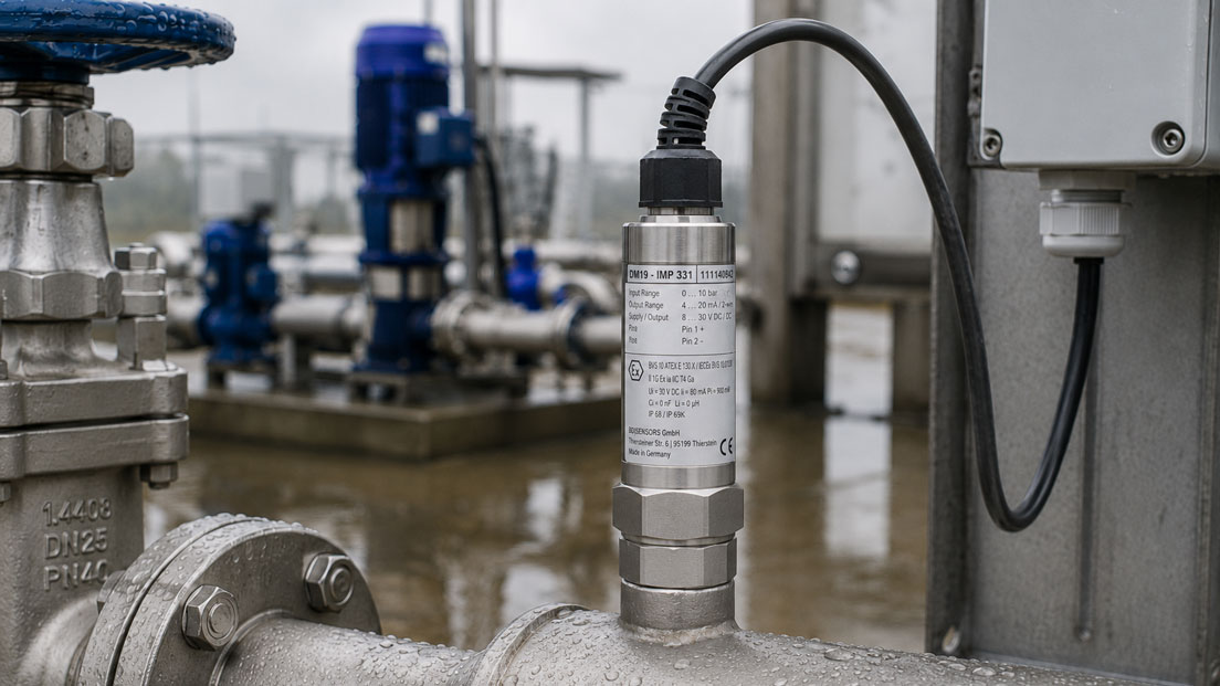
Pressure sensors are used outdoors, for example at pumping stations, water-treatment plants, mobile machinery, tanks, building-services systems and decentralised process installations. During selection, the measuring range, output signal and process connection are often the primary considerations.
However, many failures are not caused by an incorrectly selected pressure range. Moisture enters the electronics through an incorrectly installed connector, condensation accumulates inside a connection enclosure, or an unsuitable cable becomes brittle due to UV radiation and temperature changes.
An IP67 rating alone does not guarantee a permanently reliable outdoor installation. The degree of protection applies to a defined instrument version and only under the conditions specified by the manufacturer. The IP code alone does not provide information about long-term exposure to sunlight, corrosion, frost, condensation or overvoltages.
This article explains how the pressure sensor, electrical connection, cable route, mounting location and signal evaluation must be planned together so that the measuring point operates reliably even in rain, humidity and changing temperatures.
Table of contents
- Why the pressure sensor must not be considered in isolation
- What IP65, IP67, IP68 and IP69 actually mean
- Connector or fixed cable outlet?
- How condensation forms inside the sensor and connection enclosure
- Pressure equalisation in gauge-pressure sensors
- Selecting the cable material and cable routing
- Temperature changes, UV radiation and frost
- Correctly planning the mounting location and weather protection
- EMC-compliant signal transmission outdoors
- Considering overvoltage and lightning effects
- Mechanical loads and process connection
- Systematic commissioning of the outdoor measuring point
- Typical fault symptoms and their causes
- Practical example: Pressure measurement at a pumping station
- Which measuring instruments / products are suitable?
- Conclusion
- Frequently asked questions about pressure sensors used outdoors
Why the pressure sensor must not be considered in isolation
An outdoor pressure measuring point consists of more than the actual measuring cell. Several components are responsible for its reliability:
- pressure sensor and housing
- process connection and seal
- connector or cable outlet
- mating connector and cable gland
- connecting cable and its routing
- terminal box or control cabinet
- power supply and signal evaluation
- equipotential bonding, shielding and overvoltage protection
The weakest component often determines the actual resistance of the entire measuring point. A pressure sensor with IP67 protection loses its practical protection if a mating connector with an unsuitable seal is used or if the cable gland is not matched to the outside diameter of the cable.
Likewise, a fully potted cable outlet on the sensor may be highly watertight, while the other end of the cable terminates in a damp connection box. Moisture can then migrate along the conductors and cable interstices or reach the sensor through an existing pressure-equalisation capillary.
What IP65, IP67, IP68 and IP69 actually mean
The IP code describes the protection of an enclosure against the ingress of foreign objects and water under defined test conditions.
| Degree of protection | Typical meaning | Important limitation |
|---|---|---|
| IP65 | Dust-tight and protected against water jets | No statement regarding temporary immersion |
| IP67 | Dust-tight and protected against temporary immersion | Not automatically suitable for permanent underwater installation |
| IP68 | Dust-tight and designed for more extensive immersion | The depth and duration are specified by the manufacturer |
| IP69 or IP69K | Protection against powerful high-pressure and high-temperature water jets | Not equivalent to unlimited underwater resistance |
Depending on the mounting location, IP65 may be sufficient for a pressure sensor exposed to the weather if no standing water or intensive cleaning occurs. For unprotected installation, splash water, melting snow or regular plant cleaning, at least IP67 is often advisable.
IP68 is required if the sensor or its electrical connection may be temporarily or permanently submerged. The conditions stated in the data sheet regarding immersion depth, duration, cable and pressure equalisation must be observed.
The IP code does not automatically assess:
- UV resistance
- corrosion caused by salt or chemicals
- condensation inside the housing
- icing
- ozone or oil resistance of the cable
- mechanical tensile and vibration loads
- overvoltages and lightning currents
The degree of protection is therefore only one selection criterion within the complete environmental assessment.
Connector or fixed cable outlet?
Connectors simplify the replacement of a pressure sensor. A defective instrument can be replaced without opening a remote connection box. The prerequisite is that the connector type, pin assignment and seal are clearly defined.
M12 connector
M12 connectors are compact, vibration-resistant and widely used in industry. In outdoor applications, however, the matching mating connector must provide the same or a suitable degree of protection.
The following must be observed:
- fully inserted and correctly tightened mating connector
- undamaged O-ring
- suitable cable diameter for field-attachable connectors
- protective cap on unused connections
- no lateral loading from a freely suspended cable
A connector that is only hand-tightened or has a damaged seal can already allow moisture to enter during driving rain.
Valve connector in accordance with DIN EN 175301-803
Angular connectors enable simple wiring but contain several sealing points. The cable gland, flat gasket, housing and fixing screw must be installed correctly.
If the connector is mounted with the cable gland facing upwards, water can collect directly at the cable entry. A downward-running cable with a drip loop is therefore generally preferable.
Fixed cable outlet
A factory-potted cable outlet reduces the number of detachable sealing points. It is particularly suitable for permanently damp areas and restricted installation spaces.
However, this advantage only applies if the cable is suitable for the environment and the free cable end is terminated in a dry location. Damage caused by abrasion, tight bending radii or tensile loads cannot be compensated for by the degree of protection of the sensor housing.
How condensation forms inside the sensor and connection enclosure
Condensation forms when humid air comes into contact with a surface whose temperature is below the dew point. Outdoors, significant temperature changes between day and night can cause this effect regularly.
Typical situations include:
- a cold pressure sensor on a water pipe in warm, humid ambient air
- a heated control cabinet that cools down at night
- a sensor on a cooled tank
- a warm pumping station with a cold outdoor connection
- direct sunlight during the day followed by significant cooling at night
A sealed enclosure does not necessarily prevent condensation. If humid air is already trapped inside, it can condense on the housing wall, terminals or electronics when the temperature falls.
Poorly ventilated protective enclosures are particularly critical. An additional enclosure may protect against rain while simultaneously trapping moisture. This creates a permanently damp microclimate.
Possible countermeasures include:
- dry installation and wiring
- suitable ventilation or membrane elements
- condensate drainage at the lowest point of the protective enclosure
- sufficient distance from cold surfaces
- weather protection against direct cooling and sunlight
- where necessary, a control-cabinet heater or regulated ventilation
Ventilation and drainage elements may only be used if they are compatible with the required enclosure protection and explosion-protection concept.
Pressure equalisation in gauge-pressure sensors
A gauge-pressure sensor compares the process pressure with the current atmospheric pressure. For this purpose, the rear side of the measuring cell requires a connection to the ambient air.
Depending on the design, this pressure equalisation can be achieved by:
- a ventilation opening in the connector
- a membrane in the sensor housing
- a capillary inside the connecting cable
- a separate pressure-equalisation tube
This atmospheric reference is particularly important for low measuring ranges. If the ventilation path is blocked, changes in temperature and atmospheric pressure can cause a zero-point error.
A vented cable version requires a dry termination that remains open to atmospheric pressure at the free cable end. The capillary must not:
- fill with water
- be sealed airtight
- terminate in a permanently damp terminal box
- be blocked by tight bending radii or crushing
Depending on the system, the cable end is terminated in a dry, ventilated connection box with a suitable filter or desiccant element. The specifications of the sensor manufacturer must be observed.
Absolute-pressure sensors do not require atmospheric pressure equalisation. However, changing to absolute pressure is not automatically a solution because the measured variable and scaling are changed.
Selecting the cable material and cable routing
A PVC cable intended for indoor use is not automatically suitable for years of outdoor installation. The cable sheath, conductor insulation and gland must be suitable for the actual environment.
| Requirement | Property to be checked |
|---|---|
| Direct sunlight | UV and weather resistance |
| Mobile machine | Flexibility, abrasion resistance and vibration resistance |
| Hydraulic power unit | Oil and fuel resistance |
| Low temperature | Permissible bending radius and low-temperature flexibility |
| Chemical environment | Resistance to cleaning agents and process substances |
| Long cable run | Shielding, conductor cross-section and voltage drop |
The cable should initially be routed downwards from the sensor. A drip loop prevents rainwater from running directly along the cable towards the connector or cable gland.
Other important measures include:
- protecting the cable against abrasion on sheet-metal edges
- providing suitable strain relief
- avoiding tight bending radii directly at the sensor
- not positioning connectors at the lowest point of a cable loop
- not routing cables permanently through water or sludge
- sealing transitions into conduits or cable ducts
For underground installation, a cable specifically approved for this purpose or a sealed protective conduit is required. A standard sensor connecting cable should not be laid directly in the ground without additional protective measures.
Temperature changes, UV radiation and frost
The ambient temperature stated in the data sheet normally describes the air temperature at the sensor. Under direct sunlight, however, a metallic sensor housing can heat up significantly above the ambient temperature.
At the same time, cold media can cool the sensor below the temperature of the surrounding air. This results in large temperature gradients and a risk of condensation.
The following must therefore be considered during system design:
- minimum and maximum air temperature
- direct sunlight
- temperature of the process medium
- heat conduction through the pipe and connection
- rapid temperature changes
- frost and ice formation
Freezing water can mechanically stress seals, protective caps and connectors. Water accumulation should therefore be prevented by the design.
A sun shield can significantly reduce thermal loading. However, it should be designed so that air can circulate and no damp, enclosed space is created.
Correctly planning the mounting location and weather protection
The best protection is often to avoid exposing the measuring point directly to the weather. A small canopy or suitable weather shield reduces driving rain, snow and direct solar radiation.
The pressure sensor should nevertheless remain accessible for maintenance and visual inspection. Fully enclosed structures make it more difficult to identify corrosion, damaged cables or leaking process connections.
The following should be avoided when selecting the position:
- installation underneath leaking flanges or valves
- standing water at the electrical connection
- direct proximity to drain or cleaning nozzles
- installation on strongly vibrating pump housings
- an unprotected position within a traffic or work area
- thermal insulation extending over the sensor body
A protective enclosure must not block the pressure equalisation of a gauge-pressure sensor. It must also be ensured that condensation cannot collect inside the enclosure and reach the sensor through cables or capillaries.
EMC-compliant signal transmission outdoors
Pressure sensors used outdoors are frequently connected to a remote control cabinet via long cables. Motor cables running in parallel, frequency converters, pump drives and switching operations can introduce interference.
4–20 mA signal
A 4–20 mA signal is generally particularly suitable for longer cable runs. The current is less affected by voltage drops and induced interference voltages than a directly transmitted voltage signal.
Before commissioning, the loop voltage, load resistance, cable resistance and active or passive configuration must be checked.
0–10 V signal
A 0–10 V signal is more suitable for short signal paths. Voltage drops on the reference conductor and potential differences between the sensor and PLC directly affect the measured value.
For long outdoor cable runs, a 4–20 mA signal or galvanically isolated signal transmission is therefore often preferable.
Shielding and cable routing
The shielding must be connected in accordance with the manufacturer’s instructions and the grounding or equipotential-bonding concept of the installation. A general rule stating that the shield must always be connected at one end or always at both ends is not correct for every installation.
In addition:
- sensor cables should be routed separately from motor and power cables
- crossings should be made at right angles wherever possible
- large conductor loops should be avoided
- control cabinets and metallic plant components should be included in the equipotential bonding
- the power supply and analogue input should be checked for interference
The UPS4E loop calibrator can be used to simulate defined 4–20 mA signals at the control cabinet or directly on the field cable. This makes it possible to distinguish whether a fault is caused by the pressure sensor, the cable or the PLC scaling.
However, electrical simulation does not replace pressure calibration or a leak-tightness test of the sensor.
Considering overvoltage and lightning effects
Long outdoor cables can be affected by switching operations, inductive loads and atmospheric overvoltages. Cables running between different buildings or widely separated plant sections are particularly at risk.
Depending on the risk, the following may be required:
- overvoltage protection in the field and at the control cabinet
- short discharge paths to the equipotential bonding system
- galvanic isolation
- shielded or metallically protected cable routes
- integration into the lightning and overvoltage protection concept
A conventional pressure sensor is not a lightning-protection device. Even a robust EMC design cannot withstand direct lightning currents or very high partial lightning currents without damage.
Overvoltage protection devices must be suitable for the output signal, supply voltage, explosion-protection requirements and required measuring accuracy. Additional protective components can increase the load of a 4–20 mA loop.
Mechanical loads and process connection
Additional mechanical loads frequently occur outdoors. Pumps, vehicles, wind, pipe movements and frost can transfer forces to the sensor and connecting cable.
The pressure sensor should be screwed in using the wrench flats provided for this purpose. The housing or connector must not be used as an installation tool.
The following must be checked:
- process thread and sealing method
- tightening torque
- material compatibility
- risk of corrosion
- pressure surges and pulsations
- vibration and shock
- possible ice and snow loads
Long adapter chains increase the leverage. On highly vibrating equipment, a short pressure line or suitable instrument mounting bracket may be more appropriate than direct installation on the pump housing.
The electrical connection must not carry the mechanical load of the sensor. Separate strain relief is also required for a fixed cable outlet.
Systematic commissioning of the outdoor measuring point
- Check the environment: Assess the temperature, rain, sunlight, cleaning, frost and possible flooding.
- Check the instrument version: Compare the measuring range, output signal, degree of protection and temperature range with the order.
- Install the process connection: Use the correct seal and specified tightening torque.
- Make the electrical connection: Install the mating connector, cable gland and seals correctly.
- Route the cable: Provide a drip loop, strain relief and sufficient distance from power cables.
- Check the pressure equalisation: Keep the ventilation opening or capillary unobstructed and dry.
- Check the shielding and overvoltage protection: Verify that the implementation matches the plant concept.
- Test the signal: Check the zero point, full-scale value, PLC scaling and fault signals.
- Check the leak tightness: Inspect the process connection and electrical connection again after the first pressure loading.
- Create documentation: Record the connection type, cable type, protective measures and test values.
Typical fault symptoms and their causes
| Fault symptom | Possible cause | Better approach |
|---|---|---|
| Measured value fails after heavy rain | Moisture inside the mating connector or connection box | Check and dry the connector, seal and cable gland |
| Zero point changes with the weather | Blocked or damp pressure equalisation in a low gauge-pressure range | Check the venting capillary and cable termination |
| Signal is unstable while the pump is running | EMC interference, vibration or actual pressure pulsation | Perform electrical simulation and an independent pressure test |
| Sensor only operates correctly in dry weather | Damaged cable insulation or incompletely installed connector | Check the complete cable, including all connection points |
| Cable sheath becomes brittle | Insufficient UV or low-temperature resistance | Use a cable material approved for outdoor applications |
| Failure after a thunderstorm | Overvoltage through the supply, signal cable or equipotential bonding | Review the overvoltage-protection and grounding concept |
| Condensation inside the protective enclosure | Humid air is trapped and no drainage is provided | Design the housing ventilation, heating or drainage appropriately |
| IP67 sensor shows corrosion | The IP code does not assess chemical resistance | Check the housing, connection and sealing materials |
Practical example: Pressure measurement at a pumping station
The discharge pressure of a delivery pump at a municipal pumping station is to be monitored continuously. The sensor is installed outside the building on a horizontal water pipe.
The initial installation consists of a pressure sensor with an M12 connector and a 0–10 V output. The approximately 40 m connecting cable is routed to the controller together with motor cables.
After several months, sporadic fluctuations in the measured value occur during rain. The measured value also changes whenever the frequency converter of the pump changes its output frequency.
Several causes are identified during inspection:
- The field-attachable M12 mating connector is not completely sealed.
- The cable runs to the sensor from above without a drip loop.
- The 0–10 V cable runs alongside the motor cable for a long distance.
- No overvoltage protection is installed.
The measuring point is converted to a sensor with a factory-fitted cable outlet and a 4–20 mA signal. The cable is initially routed downwards and then installed inside a UV-resistant protective conduit.
The free cable end terminates in a dry connection box. Overvoltage protection suitable for the current signal is provided for the supply and signal cable. The power cable and sensor cable are routed separately.
Before the new sensor is connected, the PLC scaling is tested at 4, 12 and 20 mA using a loop calibrator. The system is then checked using a defined test pressure.
The measurement subsequently remains stable during rain and when the pump speed changes. The example shows that the original problems were caused not by the pressure measuring range, but by the combination of connection type, signal type and cable routing.
Which measuring instruments / products are suitable?
The pressure sensors and differential-pressure sensors category contains different designs for mechanical engineering, water technology, the process industry and mobile applications.
The ICS pressure sensors category contains configurable pressure transmitters with different measuring ranges, signals and electrical connections.
IMP331 for universal industrial outdoor measuring points
The IMP331 is a universal pressure transmitter with measuring ranges starting at 100 mbar and different current or voltage outputs.
Depending on the configuration, available options include an IP67 cable outlet and a cable with a pressure-equalisation tube in IP68. When selecting the configuration, the pressure reference, ambient temperature, cable material and termination of the pressure equalisation must be considered together.
IMP331Pi for precise pressure measurements
The IMP331Pi is suitable for precise measurements using a piezoresistive stainless-steel measuring cell and active temperature compensation.
Depending on the version, different electrical connections are also available, including IP67 and IP68 cable variants. The specific configuration must be suitable for the outdoor application and process connection.
WIKA MH-3 for mobile and particularly harsh applications
The WIKA MH-3 is designed for mobile machinery and high mechanical loads.
Degrees of protection up to IP69K, high shock and vibration resistance and a robust EMC design make it particularly suitable for outdoor applications on construction equipment, municipal vehicles and mobile hydraulic systems.
UPS4E for testing the 4–20 mA signal chain
The UPS4E loop calibrator can measure and simulate 4–20 mA signals.
This allows the field cable, overvoltage protection, analogue input and PLC scaling to be tested independently of the pressure sensor. An additional test using a suitable pressure reference instrument is required to assess the actual pressure measurement.
ICS Schneider Messtechnik assists with selecting the measuring range, pressure reference, output signal, electrical connection and protective measures. The required information includes the medium, pressure range, process connection, ambient temperature, possible flooding, cable length, installation situation and available PLC input.
Conclusion: The degree of protection alone does not create a reliable outdoor measuring point
A pressure sensor used outdoors must not only be suitable for the process pressure, but also for rain, humidity, temperature changes, sunlight and electrical interference sources.
The specified IP code only applies to the fully assembled instrument version. The mating connector, cable gland, seal and cable diameter are therefore just as important as the sensor housing.
Condensation can also form inside apparently sealed protective enclosures. With gauge-pressure sensors, the atmospheric pressure equalisation must additionally remain dry and functional.
A factory-fitted cable outlet reduces detachable sealing points, but requires a suitable cable material and a dry termination. Connectors simplify replacement but must be installed carefully and protected against standing water.
For long cable runs, 4–20 mA is frequently more robust than 0–10 V. Shielding, equipotential bonding and overvoltage protection must be compatible with the complete plant concept.
A permanently reliable measuring point is therefore only achieved through the correct combination of pressure sensor, electrical connection, cable route, weather protection, EMC concept and regular visual inspection.
Frequently asked questions about pressure sensors used outdoors
Is IP67 sufficient for a pressure sensor used outdoors?
IP67 may be suitable for many applications exposed to the weather. A different version may be required for permanent flooding, high-pressure cleaning or special environmental conditions.
Is an IP68 pressure sensor permanently watertight?
IP68 only applies under the conditions specified by the manufacturer. The permissible immersion depth, duration, cable and pressure equalisation must be obtained from the data sheet.
Why does the degree of protection of an M12 sensor only apply when the connector is fitted?
The seal is only created by the matching and correctly installed mating connector. Without the mating connector, the contacts and sealing surface are exposed.
What must be considered with a vented sensor cable?
The pressure-equalisation capillary must remain dry and open to the atmosphere. The cable end must not be sealed airtight or left inside a damp enclosure.
Can condensation form despite an IP67 rating?
Yes. The IP code assesses the ingress of water from outside. Humid air already present inside the enclosure can condense when the temperature falls.
Which output signal is suitable for long outdoor cables?
4–20 mA is generally more robust than 0–10 V. The available loop voltage, total load and overvoltage protection must be taken into account.
Should the sensor cable be routed upwards or downwards?
In the area of the electrical connection, it should initially run downwards. A drip loop prevents water from running directly towards the connector or cable gland.
Does a stainless-steel housing automatically protect against corrosion?
No. Resistance depends on the specific stainless-steel grade, the seals, the medium and the ambient atmosphere.
When is an additional protective enclosure useful?
A protective enclosure can be useful in the case of direct driving rain, sunlight, mechanical hazards or intensive cleaning. However, it must be ventilated or drained so that condensation does not accumulate.
How can it be determined whether a fault is caused by the sensor or the PLC?
In a 4–20 mA system, the PLC input can be simulated using a loop calibrator. The sensor is then tested separately using a known pressure.
Which information does ICS Schneider require for selection?
The required information includes the measuring range, gauge or absolute pressure, medium, process connection, output signal, cable length, ambient temperature, weather exposure, possible flooding, cleaning method and available signal evaluation.