


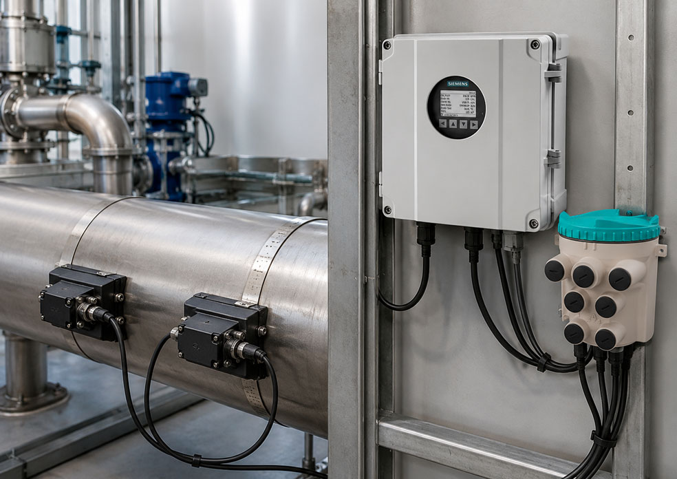
Transit-time ultrasonic flowmeters determine the flow velocity along an acoustic measuring path through the pipe. With a single-path measurement, this individual velocity value is converted to the entire pipe cross-section using a mathematical flow profile.
Under favourable installation conditions, a single measuring path can already provide reliable results. However, downstream of pipe bends, reducers, pumps, control valves or branches, the flow profile is often asymmetrical, turbulent or not fully developed. A single measuring path may then detect an area whose velocity is not representative of the entire pipe cross-section.
In multi-path ultrasonic measurement, two, three or four acoustic paths are distributed across the pipe at different positions or orientations. The electronics evaluate the individual path velocities and use them to calculate a more representative overall value.
However, additional measuring paths do not automatically improve the measurement. The sensor position, pipe data, inlet conditions, medium and parameter settings must still be correct. An incorrectly measured pipe diameter or a partially filled pipe cannot be compensated for even by four measuring paths.
Table of contents
- How transit-time measurement works
- What is meant by a measuring path
- Why the flow profile influences the measurement
- Comparison of single-, two-, three- and four-path measurement
- When two measuring paths are useful
- When three or four paths provide added value
- What multiple measuring paths cannot compensate for
- Assessing inlet runs and flow disturbances
- Multi-path measurement on large pipes
- Path comparison for diagnostics and plausibility checks
- Correctly determining sensor positions and pipe data
- Correctly weighing costs and benefits
- Typical planning and installation errors
- Practical example: Cooling-water measurement downstream of pipe bends
- Which measuring instruments / products are suitable?
- Conclusion
- Frequently asked questions about multi-path ultrasonic measurement
How transit-time measurement works
In a transit-time ultrasonic flowmeter, two ultrasonic transducers alternately transmit sound pulses with and against the direction of flow through the medium.
The sound pulse travelling with the flow reaches the opposite sensor slightly faster. The pulse travelling against the flow requires correspondingly more time. The transmitter calculates the velocity of the medium along the acoustic path from this very small transit-time difference.
Taking the pipe cross-sectional area and a correction factor for the flow profile into account, the volumetric flow rate is determined as follows:
Volumetric flow rate = average flow velocity × pipe cross-section
With clamp-on systems, the sensors are located on the outside of the pipe. The sound must therefore pass through the sensor, coupling layer, pipe wall and, where applicable, a pipe lining before entering the medium.
For accurate calculation, the measuring system requires the following information, among other data:
- pipe outside diameter or circumference
- wall thickness
- pipe material and, where applicable, lining material
- speed of sound in the medium
- temperature and viscosity
- exact sensor spacing
Incorrect pipe data cause a systematic error that can affect all measuring paths equally.
What is meant by a measuring path
A measuring path consists of a corresponding pair of ultrasonic transducers. A defined acoustic path runs between these transducers through the pipe wall and medium.
Depending on the installation method, the sound can pass directly through the medium or be reflected inside the pipe. Frequently used configurations include direct or Z-mounting and reflect or V-mounting.
In a multi-path measurement, several such sensor pairs are installed on the same pipe. The measuring paths can, for example, be arranged at different circumferential positions.
Each path provides its own measured value for:
- transit-time difference
- flow velocity
- speed of sound
- signal quality
- gain or signal reserve
The transmitter combines the path results to calculate the total flow rate. At the same time, deviations between the paths can be evaluated for diagnostic purposes.
Why the flow profile influences the measurement
In a long, straight pipe, a largely rotationally symmetrical flow profile develops depending on the Reynolds number, viscosity and pipe roughness. The velocity is higher in the centre of the pipe than directly at the pipe wall.
Under these conditions, a single correctly positioned measuring path may be sufficiently representative. The electronics convert the velocity measured along the path to the average velocity across the entire pipe cross-section using a profile factor.
Disturbances upstream of the measuring point change this profile. Typical causes include:
- single or multiple pipe bends
- two pipe bends in different planes
- partially closed control valves
- pumps and compressors
- reducers and expanders
- T-pieces and pipe junctions
- swirl or rotational flow
Downstream of a pipe bend, for example, the high-velocity flow zone may shift to one side of the pipe. A measuring path on this side then indicates an excessively high value, while a path on the opposite side detects a lower velocity.
Combining multiple positions makes the measurement less dependent on one individual local velocity zone.
Comparison of single-, two-, three- and four-path measurement
| Configuration | Typical strength | Typical application | Effort |
|---|---|---|---|
| One path | Simple and economical measuring point | Uniform profile and good inlet conditions | Low |
| Two paths | Averaging of asymmetrical profiles and improved plausibility | Continuous industrial measurement and larger pipes | Medium |
| Three paths | Additional spatial detection and path comparison | Demanding process measurements with restricted inlet conditions | Increased |
| Four paths | Extensive profile averaging, diagnostics and possible redundancy | Large pipes, balancing and high-quality process measuring points | High |
The number of paths alone does not define the measuring accuracy. A correctly installed single-path arrangement at a suitable measuring point can operate more accurately than four imprecisely positioned sensor pairs.
However, as the number of paths increases, the amount of available information about the flow profile also increases. This allows local velocity differences to be averaged more effectively and unusual path deviations to be detected.
When two measuring paths are useful
A two-path measurement is often the most economically sensible step between a simple single measurement and a more complex three- or four-path system.
The two paths are positioned so that they detect different areas or circumferential positions of the pipe. With an asymmetrical flow profile, the average of both paths is often closer to the actual cross-sectional average than the value of a single path.
Two paths are particularly useful when:
- only limited straight inlet runs are available
- the measuring point is located downstream of a pipe bend
- larger pipe diameters are being measured
- improved repeatability is required
- the measured value is used for operational or energy balances
- a plausibility comparison between two paths is required
If the two path velocities differ significantly, the total value should not simply be assumed to be correct. The deviation may indicate a distorted flow profile, an inaccurate sensor position or different acoustic conditions on the pipe wall.
When three or four paths provide added value
Three or four measuring paths are appropriate when the requirements for accuracy, availability and diagnostics are significantly higher than for a normal process indication.
Typical applications include:
- large water, cooling-water and process pipes
- balancing between plant sections
- comparative measurements for pump or heat-exchanger performance
- oil and product pipelines
- gas pipelines with demanding acoustic conditions
- measuring points with limited inlet runs
- applications with high repeatability requirements
Using several circumferential positions allows a larger proportion of the flow profile to be measured. Individual local deviations therefore have less influence on the combined measured value.
An additional advantage is diagnostics. If three paths remain stable while a fourth path suddenly shows significantly poorer signal quality or a deviating velocity, this may indicate a local installation, pipe-wall or coupling problem.
Whether the system automatically continues operating with the remaining paths if one path fails, and how the total value is then calculated, depends on the device configuration and parameter settings. This must be defined during planning.
What multiple measuring paths cannot compensate for
A multi-path measurement reduces certain influences of the flow profile. However, it does not replace professional system design.
Multiple paths cannot reliably compensate for the following problems in particular:
- partially filled pipe
- incorrect pipe diameter or wall thickness
- unsuitable or unknown lining material
- high gas-bubble or solids content outside the instrument limits
- insufficient acoustic coupling
- corrosion and deposits with unknown remaining wall thickness
- incorrectly configured viscosity or medium data
- different sensor spacings between the paths
If incorrect pipe data are entered, the same systematic error can occur in all paths. The path values may then agree well while still deviating from the actual flow rate.
Extreme flow disturbances also cannot be calculated out without limitation. If a partially closed valve is located immediately upstream of the measuring point, it should first be checked whether a more suitable measuring position is available.
Assessing inlet runs and flow disturbances
The required straight pipe runs depend on the type of disturbance, pipe diameter, flow velocity and required accuracy.
As a typical minimum guide for clamp-on transit-time systems, approximately ten pipe diameters upstream and five pipe diameters downstream of the measuring point are often used. Two pipe bends in different planes, pumps or partially open valves may require significantly longer inlet runs.
Multiple measuring paths can reduce sensitivity to a distorted profile. However, they should not be regarded as a general substitute for every missing inlet run.
The following should therefore be documented when planning the measuring point:
- type of upstream fitting or pipe geometry
- distance in pipe diameters
- orientation of the pipe bends relative to one another
- position of control and shut-off valves
- possible changes in the operating condition
During commissioning, the SITRANS FST030 allows different upstream pipe disturbances and their distance from the measuring point to be specified. This profile correction supplements a good sensor position but does not replace it.
Multi-path measurement on large pipes
As the pipe diameter increases, the probability of an uneven flow profile across the cross-section also increases. At the same time, the pipe shape, wall thickness and surface condition can vary more significantly.
Additional preliminary checks are therefore useful on large pipes:
- measure the pipe circumference at several positions
- check the wall thickness using ultrasound
- consider ovality
- inspect coatings and corrosion
- acoustically test several possible sensor positions
In such applications, a four-path measurement can provide a significantly more representative overall value than a single path. The prerequisite is that all sensor positions provide sufficient and comparable signal quality.
On very large pipes, the mounting distance between the sensors is correspondingly large. The positions must therefore be marked precisely and permanently secured against displacement.
Path comparison for diagnostics and plausibility checks
The advantage of multi-path measurement is not limited to the averaged flow value. The individual path data provide additional information about the measuring point and process.
During commissioning, at least the following should be compared:
- velocity of the individual paths
- measured speed of sound
- signal strength and signal-to-noise ratio
- required gain
- zero-point stability
- behaviour under different operating conditions
A constant difference between two paths can be caused by the flow profile. However, it can also indicate differences in sensor spacing, wall thickness or coupling layer.
If the path difference changes only during operation, deposits, gas bubbles, temperature changes or a loosened sensor may also be possible causes.
Path deviations should therefore not only be considered during commissioning but, where possible, documented as a diagnostic variable and compared over a longer period.
Correctly determining sensor positions and pipe data
Installing a multi-path system requires more care than simply fitting additional sensors.
A suitable pipe section must first be selected. On horizontal liquid pipes, sensor paths should not be positioned directly at the highest point because gas may accumulate there. On contaminated media, the lowest point may be problematic because of deposits.
Before installation, paint, rust, loose coatings and contamination must be removed from the sensor area. The surface must be sufficiently even to establish uniform acoustic coupling.
The sensor spacing and alignment must be observed precisely for each path. Even small deviations can change the calculated acoustic geometry.
After installation, each path should initially be checked individually. The combined multi-path evaluation should only be assessed once the signal shape, speed of sound and measured value are plausible.
Correctly weighing costs and benefits
Each additional path requires another sensor pair, mounting hardware, connecting cables or additional channels, as well as more time for pipe preparation and commissioning.
A multi-path solution is economically justified when a measuring error would cause higher costs than the additional sensors. This may be the case, for example, with energy balances, pump tests, product transfer or large continuous volumetric flow rates.
| Requirement | Suitable initial solution |
|---|---|
| Indicative operating display with favourable pipe routing | One path |
| Continuous process measurement with increased accuracy requirements | Two paths |
| Large pipe or significantly distorted flow profile | Two to four paths following an application review |
| Balancing and high diagnostic requirements | Three or four paths |
| Unsuitable measuring point directly downstream of a control valve | First look for a better measuring position |
The decision should therefore not be: “How many paths are technically possible?”, but rather: “What measurement uncertainty is acceptable and what flow conditions actually exist?”
Typical planning and installation errors
| Error | Possible consequence | Better approach |
|---|---|---|
| More paths are automatically equated with higher accuracy | High effort without measurable benefit | Assess the flow profile and measurement uncertainty beforehand |
| All paths are installed at acoustically unfavourable pipe positions | Weak or unstable signals | Check the pipe wall and signal quality in advance |
| Pipe data are taken only from an old drawing | Systematic error in all paths | Check the circumference and wall thickness on site |
| Different sensor spacings | Path-dependent measuring deviations | Set the spacings precisely in accordance with the installation instructions |
| Significant path deviation is simply averaged | An installation or process problem remains undetected | Investigate the cause of the deviation before approval |
| Multi-path measurement directly downstream of a partially closed valve | Flow-profile distortion that cannot be adequately controlled | Relocate the measuring point or provide additional straight pipe length |
| Partially filled liquid pipe | Signal loss and incorrect volumetric flow rate | Select a measuring point in a permanently full pipe section |
Practical example: Cooling-water measurement downstream of pipe bends
In an industrial plant, the cooling-water flow rate in a DN 800 pipe is to be monitored continuously. For structural reasons, the measuring point can only be installed a few pipe diameters downstream of two pipe bends in different planes.
During an initial single-path measurement, the signal is stable. However, the indicated flow rate changes noticeably when the sensors are moved to another circumferential position.
This dependence shows that the flow profile at the measuring point is highly asymmetrical. A single measuring path would therefore provide different results depending on its position.
For the permanent measurement, the SITRANS FS230 is configured as a four-path system. The sensor pairs are installed at different circumferential positions. During commissioning, the path velocity, speed of sound and signal quality of each path are documented individually.
The individual paths continue to show slight velocity differences. However, the combined flow value remains significantly more stable at different plant loads than the previous single-path measurement.
An additional warning is configured if one path permanently deviates significantly from the others. This allows changes at the measuring point or in the flow to be investigated at an early stage.
The example shows that multiple measuring paths can detect an unfavourable flow profile more effectively. However, the existing pipe bends do not become completely irrelevant. The remaining measurement uncertainty must still be suitable for the operational task.
Which measuring instruments / products are suitable?
The Siemens ultrasonic flow measurement category contains clamp-on and inline systems for water, process liquids, oils and selected gas applications.
SITRANS FS230 for single- to four-path measurements
The SITRANS FS230 is designed for demanding permanent clamp-on measurements. The system combines the FST030 transmitter with FSS200 ultrasonic sensors.
Single- and two-path configurations are possible with the internal Digital Sensor Link. An external FS-DSL is used for three- and four-path systems. It can be installed close to the sensors and transmits the digitised measuring signals over a greater distance to the transmitter.
Depending on the version, the system is suitable for liquids, oils and gases. The sensors are mounted externally on the pipe, so no process connection and no additional pressure loss are created.
Under suitable conditions, the specified accuracy is approximately ±0.5 to ±1% of the flow rate. The measurement uncertainty actually achieved depends, among other factors, on the pipe data, medium, flow velocity, inlet conditions and installation quality.
SITRANS FST030 as transmitter and diagnostic unit
The SITRANS FST030 processes the transit-time and diagnostic data from the connected measuring paths.
In addition to volumetric flow rate and flow velocity, other process values such as speed of sound, mass flow rate, standard volumetric flow rate and totaliser values can be provided depending on the version.
The high update rate and diagnostic capabilities are particularly helpful for dynamic processes and when comparing multiple paths.
SITRANS FUS SONOKIT for single- and two-path systems in large pipes
The SITRANS FUS SONOKIT enables the installation of a single- or two-path ultrasonic measuring system with wetted sensors.
The system is particularly suitable for large water, district-heating and irrigation pipelines where a permanently integrated measuring point is required.
ICS Schneider Messtechnik assists with selecting the number of paths, sensor size, mounting method and transmitter. The required information includes the medium, pipe diameter, wall thickness, pipe material, lining, temperature, pressure, flow velocity, upstream pipe geometry and required measurement uncertainty.
Conclusion: Multiple measuring paths primarily improve detection of the flow profile
A single ultrasonic measuring path can provide accurate and stable results under favourable inlet conditions. However, its validity depends on how representative the detected velocity is for the entire pipe cross-section.
Two paths reduce dependence on a single circumferential position and provide an additional plausibility check. Three or four paths detect a distorted flow profile more comprehensively and provide additional diagnostic information.
Multi-path measurements are particularly useful for large pipes, demanding balancing applications and restricted inlet conditions. They can also improve availability when individual paths are monitored and deviations are detected at an early stage.
However, they do not compensate for incorrect pipe data, partially filled pipes, unsuitable sensor positions or extreme process conditions. Each path must be installed correctly from both a mechanical and acoustic perspective.
The optimum number of paths therefore results from the flow profile, required measurement uncertainty, diagnostic requirements and economic importance of the measured value – not solely from the maximum possible instrument configuration.
Frequently asked questions about multi-path ultrasonic measurement
Is a four-path measurement always more accurate than a single-path measurement?
No. Under very good installation conditions, a single correctly installed path can already provide accurate results. Multiple paths mainly offer advantages with asymmetrical or disturbed flow profiles.
What does a second measuring path improve?
It detects an additional position within the pipe cross-section. This allows local velocity differences to be averaged and implausible deviations between the paths to be identified.
Do four measuring paths replace the required inlet run?
Not completely. Multiple paths can reduce flow-profile distortions, but extreme disturbances immediately upstream of the measuring point remain problematic.
Can the SITRANS FS230 measure four paths on one pipe?
Yes. With an external Digital Sensor Link, the system can be configured as a three- or four-path measurement on one pipe.
Why do different paths indicate different velocities?
Possible causes include an asymmetrical flow profile, swirl, different pipe-wall conditions, inaccurate sensor spacings or differences in acoustic coupling.
Can significantly different path values simply be averaged?
The cause should first be investigated. A large deviation may indicate an unsuitable measuring point or an installation error.
Is multi-path measurement particularly suitable for large pipes?
Yes. With large pipe diameters, the flow profile, wall thickness and pipe geometry can vary more significantly. Multiple paths then often provide a more representative overall value.
Which pipe data are required for a clamp-on system design?
At minimum, the pipe outside diameter or circumference, wall thickness, pipe material, possible lining, medium, temperature and expected flow velocity are required.
Can a multi-path system measure a partially filled pipe?
A transit-time measurement for liquids generally requires a completely filled measuring cross-section. Additional paths do not solve this problem.
Which information does ICS Schneider require for selecting the number of paths?
The required information includes the measuring task, required accuracy, nominal pipe diameter, medium, flow range, available inlet and outlet runs, upstream fittings, pipe condition and requirements for diagnostics or redundancy.