


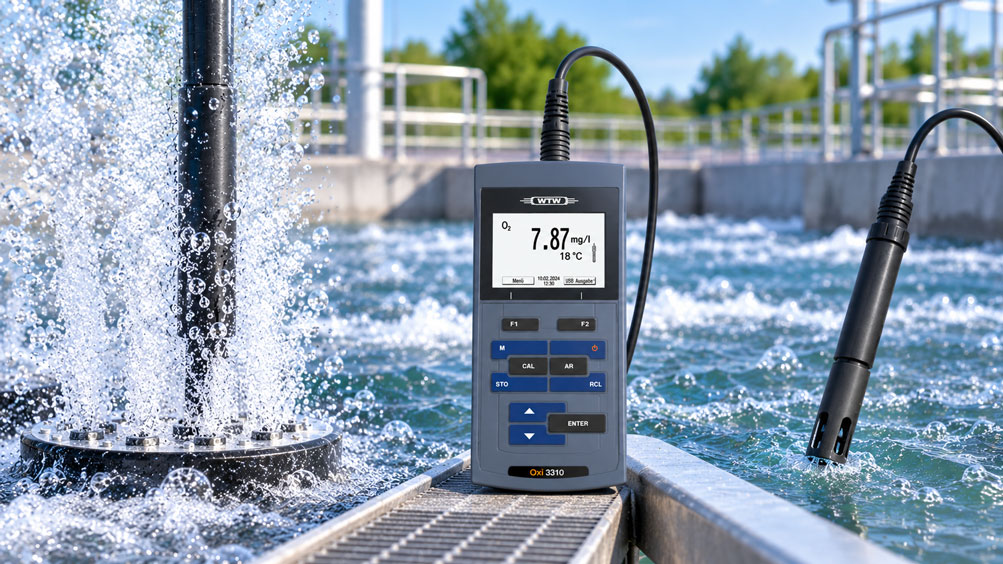
A dissolved oxygen sensor is installed in a strongly aerated basin. The oxygen supply is intensive and the water is well mixed – apparently ideal conditions for reliable oxygen measurement.
In practice, however, precisely this strong aeration can lead to unusual measured values.
The displayed oxygen value fluctuates significantly up and down within a short period. In some cases, very high saturation values appear briefly even though the actual process condition has not changed accordingly.
A common cause is air bubbles coming into direct contact with the active measuring surface of the sensor.
A dissolved oxygen sensor is fundamentally intended to determine the oxygen condition of the liquid. However, if a gas bubble is temporarily located directly on the membrane or optical sensor cap, the sensor is no longer exposed exclusively to the water locally, but instead to an interface between the liquid and gas phases.
This can result in sudden or apparently excessive oxygen readings, particularly with larger air bubbles.
In addition, strong aeration can genuinely change the dissolved oxygen concentration. A high or fluctuating measured value is therefore not automatically a measurement error.
For diagnosis, three situations must first be distinguished: an actual change in oxygen concentration, insufficient flow past the sensor, and direct interference caused by air bubbles on the sensor head.
The measuring principle used plays an important role in this assessment.
Electrochemical oxygen sensors consume oxygen at the membrane during measurement and therefore require sufficient flow. Optical sensors have much less or no such conventional flow dependency, but with unfavorable installation they can also be affected by bubbles directly at the active measuring surface.
The key point is: Under strong aeration, a dissolved oxygen sensor should not be installed where as many air bubbles as possible strike the measuring surface. What matters is a representative water sample with suitable flow, as little direct bubble contact as possible, and an installation position appropriate for the measuring principle being used.
Table of Contents
- What does a dissolved oxygen sensor measure?
- Why strong aeration affects the measurement
- What happens when air bubbles are directly on the sensor head?
- Distinguishing a real oxygen change from a measurement artefact
- How does an optical oxygen sensor work?
- How does an electrochemical oxygen sensor work?
- Why electrochemical sensors require flow
- Choosing the correct sensor position in an aeration basin
- Which sensor orientation helps prevent air bubbles?
- Why the sensor should not be positioned directly above the air diffuser
- Correctly accounting for temperature
- Correctly interpreting atmospheric pressure and oxygen saturation
- When salinity must be taken into account
- Correctly calibrating a dissolved oxygen sensor
- Distinguishing deposits on the sensor head from bubble-related problems
- Correctly assessing response time and process dynamics
- What does this mean for aeration control?
- Systematically diagnosing typical faults
- Suitable oxygen measurement technology from ICS Schneider
- Conclusion
- Frequently asked questions about dissolved oxygen sensors under strong aeration
1. What does a dissolved oxygen sensor measure?
A dissolved oxygen sensor determines the oxygen condition of a liquid.
Depending on the instrument, the measured value can be displayed, for example, as concentration in mg/l, oxygen saturation in percent or oxygen partial pressure.
These quantities are related to one another, but they do not describe exactly the same thing.
The concentration indicates how much oxygen is actually dissolved in the liquid.
Saturation, on the other hand, describes how strongly the liquid is saturated with oxygen under the current conditions relative to equilibrium with the surrounding atmosphere.
Temperature, atmospheric pressure and, where applicable, salinity therefore influence the relationship between oxygen partial pressure, saturation and concentration.
For reliable measurement, the sensor head must be in contact with the actual liquid.
It is precisely this condition that can be disturbed by strong bubble formation.
2. Why strong aeration affects the measurement
Aeration systems introduce oxygen from the air into the water.
Depending on the method used, many small or larger gas bubbles are generated and rise through the basin from the air diffuser.
At the same time, the liquid is mixed and moved.
This is desirable for oxygen transfer.
However, it can be problematic for an oxygen sensor installed directly in the bubble plume.
Rising air bubbles strike the protective guard, membrane or sensor cap, slide past it or remain temporarily attached to the surface.
Within just a few seconds, the sensor may therefore alternately detect water and an oxygen-rich gas-liquid interface.
The result can be strongly fluctuating measured values.
3. What happens when air bubbles are directly on the sensor head?
An air bubble has a significantly higher oxygen partial pressure than water containing, for example, 2 or 4 mg/l of dissolved oxygen.
If a larger bubble lies directly against the active sensor surface or bursts there, the immediate measuring environment changes abruptly.
The sensor may respond with a brief increase in the measured value.
Manufacturers of oxygen sensors explicitly point out this effect.
For measurements in strongly aerated basins, it is therefore recommended to orient the active sensor surface so that rising bubbles slide past it as much as possible rather than remaining on the surface or bursting directly on it.
This error is particularly noticeable as a rapid positive peak followed by a subsequent decrease.
A single brief high measured value should therefore not automatically be interpreted as an actual oxygen peak in the entire basin.
4. Distinguishing a real oxygen change from a measurement artefact
Strong aeration can, of course, also genuinely change the dissolved oxygen concentration.
Not every high measured value is therefore incorrect.
The time profile is particularly useful for diagnosis.
| Observation | Possible cause | Typical behavior |
|---|---|---|
| Short, steep positive peaks | Air bubble directly on the measuring surface | Very rapid change and rapid return |
| Slow, continuous increase | Actual increase in dissolved oxygen | Process follows the aeration output |
| Continuous strong fluctuations | Sensor located directly in the bubble plume | Value correlates with bubble impact |
| Low stable value despite expected high concentration | Insufficient flow with an electrochemical sensor | Value increases with stronger water movement |
| Slow drift | Deposits, ageing or calibration problem | No direct relationship with individual bubbles |
A particularly simple test is to temporarily change the sensor position or orientation so that significantly fewer bubbles strike the sensor head.
If the signal immediately becomes more stable, bubble exposure is probably at least partly responsible.
5. How does an optical oxygen sensor work?
Optical dissolved oxygen sensors use oxygen-dependent luminescence or fluorescence in a sensor cap.
An optical indicator is excited by light.
Oxygen then influences the intensity or decay time of this luminescence.
The oxygen partial pressure is determined from this change.
Unlike conventional electrochemical measurement, the method consumes practically no oxygen at the measuring surface.
A minimum water flow is therefore generally not required.
However, water movement can improve the response time because changes in the medium reach the measuring surface more quickly.
Even an optical sensor should be installed under strong aeration so that larger air bubbles do not remain permanently on the sensor cap.
6. How does an electrochemical oxygen sensor work?
Electrochemical oxygen sensors have a gas-permeable membrane and an electrochemical system behind this membrane.
Oxygen diffuses from the water through the membrane and is electrochemically converted inside the sensor.
The resulting current is related to the oxygen partial pressure.
With this measuring principle, oxygen is consumed at the sensor surface.
This can create an oxygen-depleted boundary layer directly in front of the membrane.
Without sufficient water movement, the consumed oxygen is not replaced quickly enough.
The sensor can then indicate a lower value than is actually present in the surrounding water.
This means that with electrochemical sensors, both insufficient flow and excessive direct bubble contact can be problematic.
7. Why electrochemical sensors require flow
The required flow velocity is product-specific.
For the galvanic WTW CellOx 325, for example, the manufacturer specifies different minimum velocities depending on the required measurement accuracy.
For a measurement accuracy of 10%, a flow velocity of more than 3 cm/s is specified.
For 5%, 10 cm/s is specified, and for 1%, approximately 18 cm/s.
These values demonstrate an important relationship: A moving medium is fundamentally necessary for a galvanic oxygen sensor.
Strong aeration does provide plenty of water movement, but the required flow should come from liquid movement rather than from gas bubbles striking the membrane directly.
For controlled laboratory or comparative measurements, a stirrer or defined flow can therefore be considerably more reproducible than turbulent aeration.
8. Choosing the correct sensor position in an aeration basin
The installation position is highly important for continuous oxygen measurement.
The sensor should measure a representative area of the process.
Directly above an air diffuser, the bubble density is often at its highest.
At this location, the measurement can be influenced more strongly by the gas phase than at a point several decimeters or meters to the side.
A position in well-mixed water but outside the most intense bubble plume is often more suitable.
The proximity to the inlet, outlet, wall, water surface or dead zone must also be taken into account.
The best position is not necessarily the point where the highest oxygen value is measured.
Instead, it should represent the oxygen condition relevant to process control.
9. Which sensor orientation helps prevent air bubbles?
In addition to the position, the orientation of the sensor head also affects how air bubbles interact with the measuring surface.
With an unfavorably upward-facing horizontal surface, bubbles can adhere more easily under certain geometries.
With other sensor designs, an inclined or inverted installation can cause rising bubbles to slide past the measuring surface.
Manufacturers of optical process sensors sometimes deliberately use a beveled sensor cap to support this effect by design.
For portable sensors in strongly aerated basins, it is sometimes recommended to orient the probe so that bubbles do not burst directly on the membrane.
However, the permitted orientation must be checked in the operating instructions of the specific sensor.
There is no universal installation orientation for every DO measuring principle.
10. Why the sensor should not be positioned directly above the air diffuser
An air diffuser produces the locally highest concentration of gas bubbles.
Turbulence, flow velocity and gas content are also particularly high at this point.
For process control, this point is often not representative of the entire basin.
A sensor installed directly above a diffuser can therefore have two problems at the same time:
The actual local oxygen input is above average and the measuring surface is additionally exposed directly to gas bubbles.
The measured result may therefore be physically correct or partially correct for that specific location while still being unsuitable for controlling the overall plant.
A representative measuring point should therefore be selected based on the flow pattern, basin geometry, diffuser arrangement and control objective.
11. Correctly accounting for temperature
The solubility of oxygen in water depends strongly on temperature.
As the water temperature increases, the amount of oxygen that can be dissolved at equilibrium at the same partial pressure decreases.
Modern dissolved oxygen sensors therefore normally have an integrated temperature sensor.
For correct compensation, however, this temperature sensor must also be fully immersed in the representative liquid.
Partially immersed sensors or strong temperature gradients can lead to additional deviations.
During troubleshooting, not only the oxygen value but also the simultaneously displayed temperature should therefore be checked for plausibility.
12. Correctly interpreting atmospheric pressure and oxygen saturation
Oxygen saturation is also influenced by atmospheric pressure.
With the same water and temperature, a change in atmospheric pressure changes the oxygen partial pressure at the water surface.
Measuring instruments can account for this influence using an integrated atmospheric pressure sensor or corresponding compensation.
The ProfiLine Oxi 3310 offered by ICS, for example, features automatic atmospheric pressure compensation.
Especially for saturation values, it should therefore be checked whether the pressure compensation is working correctly or is properly configured.
An unusually high percentage value is not automatically caused solely by air bubbles.
Actual supersaturation, temperature changes and the reference pressure can also play a role.
13. When salinity must be taken into account
Dissolved salts reduce the oxygen solubility of water.
For samples with high salinity, a corresponding salinity correction must therefore be taken into account.
For typical municipal wastewater, this influence is often smaller than in seawater, aquaculture or concentrated process solutions.
However, during comparative measurements, care should be taken to ensure that both instruments or sensors operate with the same correction parameters.
Otherwise, two technically sound sensors can display different concentration values.
14. Correctly calibrating a dissolved oxygen sensor
Calibration should not be performed directly in a strongly turbulent bubble plume.
Defined calibration conditions are used for oxygen sensors depending on the measuring principle.
For galvanic WTW sensors such as CellOx or DurOx, for example, dedicated OxiCal calibration vessels are used.
For optical FDO sensors, verification or user calibration is performed in water-vapor-saturated air.
It is essential that the sensor is sufficiently temperature-stable before evaluation and that the active measuring surface is clean and in the condition specified by the manufacturer.
Incorrect calibration can subsequently shift every process value systematically.
Before recalibrating because of fluctuating values, it should therefore first be checked whether the cause is simply the installation position or direct bubble contact.
15. Distinguishing deposits on the sensor head from bubble-related problems
Wastewater and process water can create biological deposits, grease, solids or other deposits on the sensor.
A contaminated membrane or sensor cap changes mass transfer and can affect both response time and measured value.
The surface properties also change.
This may make it easier for air bubbles to adhere to the surface.
A bubble problem and a contamination problem can therefore occur at the same time.
In the case of persistently abnormal measured values, the sensor head should be cleaned in accordance with the manufacturer’s instructions and then checked again.
Mechanically aggressive cleaning should be avoided because optical sensor caps and thin membranes in particular can be damaged.
16. Correctly assessing response time and process dynamics
An oxygen sensor does not reproduce an actual change without delay.
The response time is influenced by the measuring principle, sensor cap or membrane, temperature and flow.
For the optical WTW FDO 925, for example, a t90 of less than 30 seconds is specified at 20 °C in stirred solution.
The sensor does not require a minimum flow velocity, but liquid movement improves the response behavior.
During a rapid change in aeration, it should therefore not be expected that every sensor will immediately display the final new process value.
Diagnosis must distinguish between actual process dynamics, sensor response time and short-term bubble artefacts.
17. What does this mean for aeration control?
In biological wastewater treatment plants, the oxygen value is often used directly to control the blowers or aerators.
A strongly fluctuating sensor signal can therefore directly influence energy consumption and process control.
If the sensor repeatedly indicates values that are too high because of impacting air bubbles, the control system may unnecessarily reduce aeration.
When the measured value subsequently drops again, the control system increases aeration once more.
The system can therefore begin regulating more aggressively than the actual biological process requires.
Pure electronic filtering is only of limited help in this situation.
It can smooth individual peaks, but it does not correct a fundamentally unsuitable sensor position.
For robust control, a representative measuring point with as little interference as possible should therefore be selected first.
18. Systematically diagnosing typical faults
| Observation | Possible cause | Recommended check |
|---|---|---|
| DO value shows very short positive peaks | Bubbles burst directly on the measuring surface | Change the sensor position or orientation |
| Measured value becomes more stable when aeration is switched off | Direct bubble influence or strong turbulence | Move the sensor away from the main bubble plume |
| Electrochemical sensor reads too low in still water | Insufficient flow | Provide defined liquid movement |
| Value increases when the sensor is moved | Flow dependency of the electrochemical sensor | Check flow according to the manufacturer’s specifications |
| DO value permanently too high | Actual supersaturation, calibration or bubble attachment | Perform a reference measurement outside the bubble plume |
| Measurement responds very slowly | Contaminated membrane/sensor cap or slow sensor characteristics | Clean the sensor and check response time |
| Measured value drifts over several days | Membrane, electrolyte, sensor cap or calibration | Check sensor condition and calibration |
| Two sensors in the same basin show significantly different values | Different position, bubble exposure or local O₂ distribution | Temporarily compare the sensors side by side at a representative point |
19. Suitable oxygen measurement technology from ICS Schneider
ICS Schneider Messtechnik offers instruments for measuring pH, conductivity and dissolved oxygen in water, environmental, laboratory and process applications. An overview can be found under pH / Conductivity / Dissolved Oxygen Measuring Instruments.
19.1 ProfiLine Oxi 3310
The ProfiLine Oxi 3310 is a professional portable measuring instrument for dissolved oxygen.
The measured value can be displayed as oxygen concentration, saturation or partial pressure.
The instrument features an interval-controlled data logger with memory for up to 5,000 measured values and is therefore also suitable for observing fluctuations over time.
An integrated atmospheric pressure sensor provides pressure compensation for the oxygen measurement.
In the available set version, the instrument is supplied with the galvanic CellOx 325 oxygen sensor.
19.2 CellOx 325
The CellOx 325 is a membrane-covered galvanic dissolved oxygen sensor.
Its measuring range extends up to 50 mg/l O₂ or 600% oxygen saturation.
Because the galvanic measuring principle consumes oxygen at the membrane, sufficient flow is required.
In a strongly aerated application, the objective should therefore not simply be to direct as many bubbles as possible onto the membrane.
The goal is sufficient and preferably uniform liquid movement while simultaneously reducing direct bubble contact.
19.3 Optical Sensors for Strongly Aerated Applications
Optical dissolved oxygen sensors can be particularly suitable for continuous process measurements because they do not consume oxygen at the measuring surface and therefore do not require a conventional minimum flow velocity.
However, in strongly aerated basins the mechanical design of the sensor cap remains relevant.
For corresponding process sensors, beveled sensor caps are available, for example, which allow air bubbles to slide past more easily.
The suitable device version depends on the measuring range, application, installation conditions, cleaning requirements, required dynamics and interface.
19.4 Device Selection by ICS Schneider
For selecting a suitable oxygen measurement solution, relevant information includes the medium, expected oxygen range, temperature, salinity, type and intensity of aeration, immersion depth, flow, portable or continuous measurement and required data logging.
For process measurements, it should additionally be described how the sensor can be installed and whether it will be used directly in an aeration zone, in a bypass or in a less turbulent area of the basin.
20. Conclusion
Strong aeration does not automatically provide optimum conditions for a dissolved oxygen sensor.
Aeration does provide oxygen input and water movement, but it can also bring large quantities of air bubbles directly to the measuring surface.
If these bubbles strike the membrane or sensor cap or remain attached there temporarily, the sensor can indicate sudden or apparently excessive values.
The sensor position is therefore particularly important.
The sensor should measure a representative area of the water and should not be installed directly in the most intense bubble plume of the air diffuser.
The orientation can also help ensure that rising bubbles slide past the measuring surface.
The measuring principle must also be taken into account.
Galvanic and other electrochemical sensors require sufficient flow because they consume oxygen at their membrane.
Optical sensors generally do not require this minimum flow, but with unfavorable installation they can still be affected by direct bubble exposure.
Temperature, atmospheric pressure, salinity, sensor contamination and calibration condition additionally influence the measurement.
For reliable diagnosis, the following sequence therefore applies:
Check the sensor position → reduce direct bubble exposure → verify the permitted sensor orientation → take the measuring principle into account → ensure sufficient water flow for electrochemical sensors → check temperature and pressure for plausibility → clean the sensor head → check calibration → compare the measured value outside the bubble plume → only then modify filtering or process control.
The most important practical principle is therefore: For good dissolved oxygen measurement, the sensor does not need as many air bubbles as possible, but rather representative contact with the liquid under conditions that suit the measuring principle being used.
21. Frequently asked questions about dissolved oxygen sensors under strong aeration
21.1 Can air bubbles affect a dissolved oxygen sensor?
Yes. Larger bubbles that sit directly on the active measuring surface or burst there can cause sudden or excessively high oxygen readings.
21.2 Why does the sensor often indicate too much oxygen when air bubbles are present?
The measuring surface is locally exposed to an oxygen-rich gas phase or gas-liquid interface. This differs significantly from the dissolved oxygen in the surrounding water.
21.3 Does a high value always mean a bubble-related error?
No. Strong aeration can also genuinely lead to high oxygen concentrations or supersaturation. The time profile and a comparative measurement at another position help distinguish between the two.
21.4 Where should the oxygen sensor be positioned in an aeration basin?
In a well-mixed area that is representative of the process, preferably not directly in the most intense bubble plume of an aerator.
21.5 Should the sensor be installed directly above the air diffuser?
This is generally unfavorable because both the gas fraction and bubble impact are particularly high there. However, the optimum position depends on the basin and process geometry.
21.6 Can a different sensor orientation help?
Yes. Depending on the sensor design, inclined, vertical or inverted installation can prevent rising bubbles from remaining permanently on the active surface.
21.7 Does an optical oxygen sensor require flow?
For sensors such as the WTW FDO 925, no minimum flow velocity is required. However, liquid movement can improve the response behavior.
21.8 Does a galvanic oxygen sensor require flow?
Yes. Because oxygen is consumed at the membrane during electrochemical measurement, sufficient fresh measuring medium must continuously flow past the sensor.
21.9 What flow velocity does the CellOx 325 require?
WTW specifies more than 3 cm/s for 10% measurement accuracy, 10 cm/s for 5% and 18 cm/s for 1% for the CellOx 325.
21.10 Does this mean strong aeration is ideal for the CellOx 325?
Not automatically. It does provide water movement, but it can also bring interfering air bubbles directly to the membrane. The decisive factor is liquid flow rather than the strongest possible bubble impact.
21.11 Why does the measured value fluctuate more strongly while aeration is operating?
Possible causes include direct air bubbles on the measuring surface, actual local oxygen fluctuations or strong turbulence at the measuring point.
21.12 Can a digital filter solve the problem?
A filter can smooth individual peaks, but it cannot correct an unsuitable sensor position or air bubbles on the measuring surface.
21.13 Why is temperature important?
Oxygen solubility decreases as temperature increases. Correct temperature measurement and compensation are therefore part of dissolved oxygen measurement.
21.14 Why is atmospheric pressure taken into account?
Atmospheric pressure influences the oxygen partial pressure and therefore particularly the calculation of oxygen saturation.
21.15 When must salinity be corrected?
When the medium contains relevant quantities of dissolved salts, for example in seawater, aquaculture or saline process solutions.
21.16 Can deposits also cause fluctuating values?
Yes. Deposits on the membrane or sensor cap can influence mass transfer, response time and bubble adhesion.
21.17 Should the sensor be recalibrated immediately if values fluctuate?
No. Sensor position, bubble influence, flow, contamination and temperature should be checked first. Recalibration cannot correct an installation problem.
21.18 Which ICS instrument is suitable for portable dissolved oxygen measurements?
The ProfiLine Oxi 3310 is designed for portable and documented dissolved oxygen measurements and can measure concentration, saturation, partial pressure and temperature.
21.19 Which sensor is included with the Oxi 3310 Set 1?
The set is supplied with the galvanic CellOx 325 oxygen sensor.
21.20 What information does ICS Schneider require for device selection?
Useful information includes the medium, oxygen range, temperature, salinity, type and intensity of aeration, flow velocity, installation position, portable or continuous measurement, required data logging and whether the measured value is intended only for documentation or is used directly for process control.