


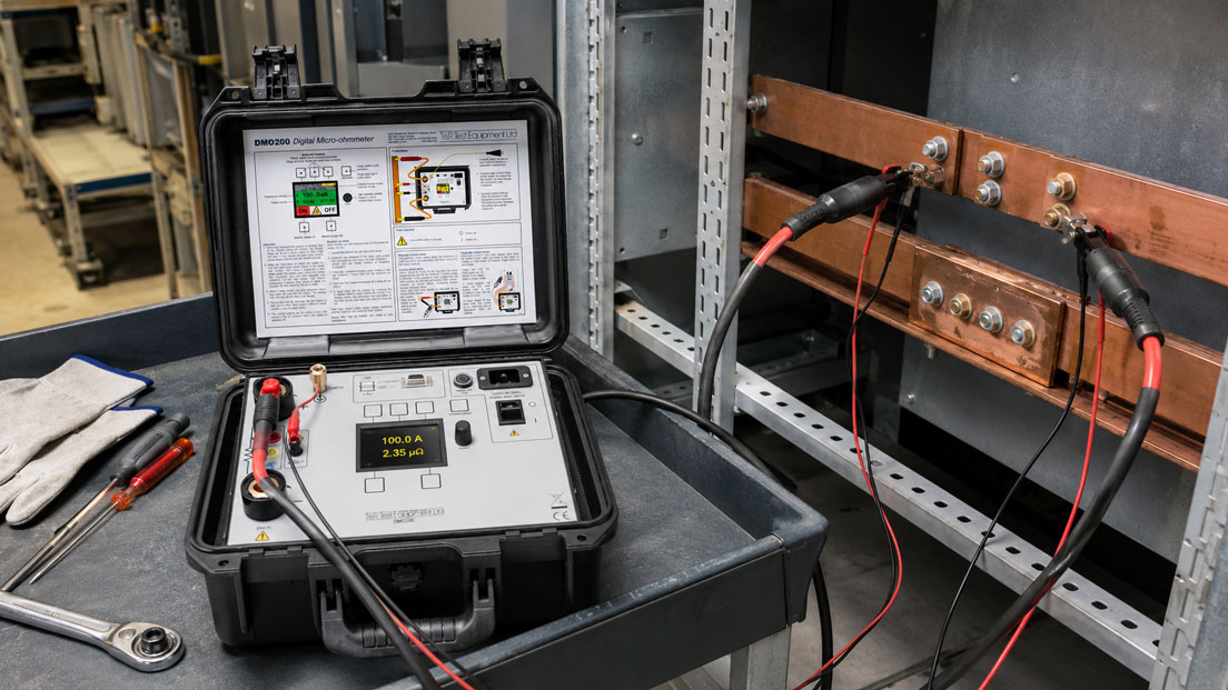
For busbars, circuit breakers, welded connections or high-current cables, just a few microohms can make a significant difference to power loss and heating. However, such low resistances can hardly be assessed reliably with an ordinary multimeter.
The reason lies in the resistance of the test leads and contact points. These resistances may be greater than the actual resistance of the test object. With a two-wire measurement, these components are included in full and can make a good connection appear poor or conceal changes in the actual contact point.
For precise low-resistance measurements, the four-wire or Kelvin measurement method is therefore used. Two leads carry a defined test current through the test object. Two separate high-impedance sense leads measure the voltage drop directly across the section being assessed. The micro-ohmmeter calculates the resistance from the test current and voltage.
Suitable instruments can be found in the ICS category Resistance Meters and Micro-Ohmmeters. Additional systems for testing switches, transformers and power installations are grouped under Test Equipment for Power Supply Systems.
Table of Contents
- Why are a few microohms relevant?
- Why is two-wire measurement unsuitable?
- How does four-wire measurement work?
- Correctly positioning Kelvin clamps and measuring points
- Selecting the appropriate test current
- Avoiding thermoelectric voltages and offset errors
- Correctly assessing oxidation and contact surfaces
- Testing bolted and busbar connections
- Measuring circuit breakers and disconnecting contacts
- Accounting for parallel paths and grounding at both ends
- Accounting for temperature and self-heating
- Recommended measurement procedure
- Defining limits and comparative measurements
- Practical example: Abnormal busbar connection
- Typical errors in low-resistance measurements
- What should be included in the measurement report?
- Which products and solutions are suitable?
- Conclusion
- Frequently asked questions
Why are a few microohms relevant?
The voltage drop across an electrical resistance is calculated as follows:
U = I × R
The power loss converted into heat is:
P = I² × R
Because power loss increases with the square of the current, even small contact resistances can cause considerable heating at high operating currents.
For example, a contact resistance of 10 µΩ at an operating current of 2,000 A generates:
P = 2,000² A² × 10 µΩ = 40 W
This power loss is concentrated at the connection. If the resistance continues to increase because of a loose bolted connection, oxidation or damaged contact surfaces, heating, material ageing and further deterioration of the connection can reinforce one another.
Typical applications for low-resistance measurements include:
- busbar and bolted connections,
- main contacts of circuit breakers and disconnectors,
- high-current cables and cable lugs,
- welded and crimped connections,
- earthing and equipotential-bonding connections,
- motor and transformer windings,
- current-transformer connections,
- shunts and precision resistors,
- battery connectors and cell connectors.
Why is two-wire measurement unsuitable?
In a two-wire measurement, the test current and voltage measurement use the same leads. The measuring instrument therefore detects more than just the resistance of the test object.
In simplified form:
RMeasurement = RTest object + RLead 1 + RLead 2 + RContacts
For example, if a contact resistance of 20 µΩ is to be measured, the test leads and probes alone may have resistances in the milliohm range. The value being measured is then completely lost within the measurement error.
| Characteristic | Two-wire measurement | Four-wire measurement |
|---|---|---|
| Test current and voltage measurement | Shared leads | Separate current and sense leads |
| Influence of test leads | Included in the measurement | Largely eliminated |
| Influence of current contacts | Included in the measurement | Located outside the voltage measurement |
| Suitable for | Medium and high resistances | Milliohms and microohms |
| Typical instruments | Multimeters | Micro-ohmmeters |
Zeroing the two-wire test leads can partially compensate for a constant lead resistance. However, fluctuating contact resistances at the test probes remain. This is therefore not a substitute for four-wire technology when reliable microohm measurements are required.
How does four-wire measurement work?
Four-wire measurement uses two current leads and two voltage-sensing leads:
- Force or Current: carries the defined test current through the test object.
- Sense or Potential: measures the voltage drop directly across the relevant section.
Because the voltage-measurement input has a very high impedance, practically no relevant current flows through the sense leads. Their lead and contact resistances therefore do not cause any significant additional voltage drop.
The instrument calculates:
R = USense / ITest
It is essential that the sense contacts are positioned between the two current contacts. Only the section between the sense points is included in the measurement result.
The voltage drop across the outer current clamps and current leads is therefore not included in the measurement. It may be relatively high, provided that the micro-ohmmeter can still generate the configured test current reliably.
Correctly positioning Kelvin clamps and measuring points
A Kelvin clamp contains two electrically isolated contacts on each side. One contact carries the test current, while the other measures the voltage.
For large busbars or circuit breakers, four separate leads are frequently used. This allows the current and sense connections to be positioned precisely.
The following applies for correct contact placement:
- Position the current contacts outside the section being measured.
- Position the sense contacts inside the current contacts.
- Place the sense points as close as possible to the connection being assessed.
- Do not measure on paint, dirt, grease or loose oxide layers.
- Do not position the sense contacts on bolt heads or washers when assessing the busbar joint.
- Secure all contacts against slipping.
- Ensure sufficient contact pressure.
- Clearly identify the current and sense leads.
For a bolted busbar joint, the sense points are positioned on the two busbars immediately before and after the overlapping section. If they are positioned too far away, the measurement result additionally includes the resistance of longer busbar sections.
If the sense contacts are positioned outside the current contacts, the current distribution may become undefined. The result can then no longer be clearly assigned to the intended section.
Selecting the appropriate test current
A higher test current generates a larger voltage drop across the same resistance. In many cases, this improves the ratio between the useful signal and interference voltage.
However, the highest possible test current is not automatically the best choice. The following factors must be considered:
- type and rated current of the test object,
- expected resistance range,
- thermal load capacity,
- permissible test duration,
- contact quality of the test leads,
- manufacturer specifications for the equipment,
- comparability with previous measurements.
Portable instruments with test currents of up to 10 A are suitable for connections, cables, windings and many maintenance measurements. For large circuit breakers, high-current contacts and massive busbars, test currents of 100 A, 200 A or more may be required or specified by the manufacturer.
The test current should actually reach the configured value during the measurement. If poor current contacts, long leads or excessive total resistance limit the current, the measurement result may be unstable or not comparable with a reference measurement.
On sensitive contact surfaces, a very high test current may heat or alter an unstable contamination layer. The test must therefore be performed using a current that is suitable for the equipment and properly documented.
Avoiding thermoelectric voltages and offset errors
Thermoelectric voltages are generated at junctions between different metals when temperature differences are present. Although these voltages are often only in the microvolt range, they can represent a relevant proportion of the measuring signal during a microohm measurement.
At a test current of 100 A, a resistance of 1 µΩ generates a voltage drop of only:
U = 100 A × 1 µΩ = 100 µV
A thermoelectric voltage of just a few microvolts can therefore already cause a visible change in the result.
Suitable countermeasures include:
- allowing the test object and test leads to reach thermal stability,
- avoiding warm and cold air currents at the contact points,
- using similar connection materials,
- activating the instrument’s offset compensation,
- repeating the measurement with reversed current direction.
With current reversal, the following applies in simplified form:
U+ = R × I + UThermo
U− = −R × I + UThermo
The resistance can then be determined using:
R = (U+ − U−) / (2 × I)
The constant thermoelectric voltage is thereby largely removed from the result.
Correctly assessing oxidation and contact surfaces
Oxidation, contamination and insufficient contact force influence the contact resistance. A distinction must be made between the electrical connection of the test leads and the actual connection being tested.
The test contacts must establish a stable metallic connection. However, the bolted, crimped or switching connection being examined must not be cleaned or retightened without authorisation before a condition measurement. Doing so would alter the original condition.
A suitable procedure is:
- Measure the connection in the condition in which it was found.
- Document the measured value, temperature and contact position.
- Clean, inspect or reassemble the connection with the specified torque in accordance with an approved work instruction.
- Repeat the measurement using the same test current and identical measuring points.
For aluminium connections, particular attention must be paid to the surface treatments, contact compounds, washers and tightening procedures specified by the component manufacturer. A general cleaning recommendation cannot replace the specific installation instructions.
Testing bolted and busbar connections
For busbars, the measurement should determine the contact resistance at the joint and not the resistance of an arbitrarily long section of busbar.
Suitable arrangement:
Outer current connection → sense point before the overlap → bolted joint → sense point after the overlap → outer current connection
For comparable results, the same geometric distances should be used for all phases. Different sense-point positions alone can cause deviating values because of the additional material resistance.
Where several bolts are arranged in parallel, a single resistance measurement cannot reliably determine which bolt is transmitting the clamping force unevenly. A visual inspection, torque check in accordance with the manufacturer’s instructions and thermographic inspection under load may additionally be required.
Thermography shows the actual heating during operation. Low-resistance measurement, by contrast, can detect an increased contact resistance while the system is de-energised. The two methods complement one another but do not replace each other.
Measuring circuit breakers and disconnecting contacts
For circuit breakers, the resistance of the complete main current path of one phase is normally measured. Depending on the design, this includes:
- connection surfaces,
- fixed and moving main contacts,
- flexible current-carrying strips,
- internal bolted connections,
- plug-in or disconnecting contacts.
All poles must be in the same defined switching position. The circuit breaker is operated several times in accordance with the manufacturer’s instructions and is then fully closed.
The measured values for the phases should be compared under identical conditions. A significant deviation may indicate contaminated contacts, uneven contact pressure, damaged flexible conductors or a defective internal connection.
However, a low total resistance does not prove that every individual internal contact point is free from defects. For complex circuit breakers, additional measuring points or dynamic resistance measurement may be required.
Accounting for parallel paths and grounding at both ends
If the test object is electrically connected through earthing points, parallel conductors, neighbouring busbars or other equipment, the test current may divide between several paths.
The micro-ohmmeter still measures the injected current and the voltage across the test object, but part of the indicated current may not flow through the intended section. The resulting resistance may therefore appear too low.
Typical parallel paths are caused by:
- high-voltage equipment grounded at both ends,
- busbars connected in parallel,
- closed bus-coupler switches,
- cable shields and equipotential bonding,
- multiple conductors routed in parallel,
- transformer or motor windings.
Where possible, parallel paths should be isolated and clearly disconnected. If this is not permissible for safety reasons, a measuring method designed for this condition is required.
With methods for test objects grounded at both ends, the current actually flowing through the test object is measured separately. The current clamp, connection sequence and calculation used must be compatible with the micro-ohmmeter and the intended procedure.
Accounting for temperature and self-heating
The resistance of metallic conductors changes with temperature. For copper, the temperature coefficient near 20 °C is approximately 0.00393 per kelvin.
The following simplified equation can be used to convert a measured value to 20 °C:
R20 = RT / [1 + α × (T − 20 °C)]
Here, α is the temperature coefficient of the material. For accurate calculations, the material, alloy and manufacturer’s specifications must be considered.
At very low resistance values, self-heating caused by the test current may also become measurable. If the measured value continuously increases during a longer test, the cause may be either unstable contact placement or heating of the test object.
For comparative measurements, the following should therefore be documented:
- ambient and object temperature,
- test current,
- test duration,
- time at which the measured value was recorded,
- where applicable, the value converted to a reference temperature.
Recommended measurement procedure
- De-energise the test object: Secure it against reconnection, verify the absence of voltage and discharge any stored energy.
- Define the test objective: Specify exactly which contact or conductor section is to be assessed.
- Check parallel paths: Consider earthing connections, parallel conductors and closed switching devices.
- Select the instrument: Match the measuring range, test current, leads and permissible application to the test object.
- Define the measuring points: Mark reproducible current and sense points.
- Connect the current leads: Position them outside the section being measured with sufficient contact force.
- Connect the sense leads: Position them inside the current contacts, directly before and after the relevant connection.
- Record the temperature: Document the object and ambient temperature.
- Increase the test current gradually: For inductive test objects, observe the measuring-instrument manufacturer’s instructions.
- Wait for stabilisation: Observe the test current, voltage and resistance.
- Reverse the current direction: Where available, use automatic or manual offset compensation.
- Repeat the measurement: Check reproducibility without moving the contacts.
- Record comparative values: Measure other phases or equivalent connections under identical conditions.
- Switch off the test current: Allow inductive test objects to discharge completely.
- Document the result: Record the measured value, current, temperature, connection points and assessment.
Defining limits and comparative measurements
There is no universal contact-resistance limit that applies to all circuit breakers, busbars and connections.
Suitable assessment criteria include:
- manufacturer limits for the equipment,
- acceptance criteria specified by the system operator,
- measurements taken during initial commissioning,
- previous measurements on the same connection,
- comparison between equivalent phases or poles,
- values from identically constructed systems,
- temperature and the test current used.
An absolute value may be low but still abnormal if it has increased significantly since the previous inspection. Conversely, a higher value may be inherent in the design and permissible if it occurs reproducibly on all equivalent poles.
Limits should therefore not be defined only during the measurement. The test current, measuring points, temperature reference and assessment criteria belong in the work or test instruction.
Practical example: Abnormal busbar connection
In a low-voltage main distribution system, three identically constructed copper busbar connections are measured using a test current of 100 A.
The sense points are positioned immediately before and after the bolted overlap. The object and ambient temperatures are approximately the same for all measurements.
| Phase | Initial measurement | Repeat measurement |
|---|---|---|
| L1 | 6.4 µΩ | 6.5 µΩ |
| L2 | 6.7 µΩ | 6.6 µΩ |
| L3 | 11.8 µΩ | 11.7 µΩ |
The measurement is reproducible. However, L3 has a significantly higher resistance than the two equivalent connections.
Following approval, the connection is dismantled. Oxidation and uneven pressure distribution are found on one contact surface. The surfaces are prepared in accordance with the assembly instructions, and the connection is reassembled using the specified components and torques.
The subsequent measurement gives:
L3: 6.6 µΩ at 100 A
The example demonstrates why comparative measurements between geometrically identical phases are particularly informative. A simple continuity test would merely have indicated a conductive connection both before and after the repair.
Typical errors in low-resistance measurements
| Error | Possible consequence | Suitable corrective action |
|---|---|---|
| Two-wire measurement used for microohms | Lead and contact resistances dominate the result | Use four-wire Kelvin measurement |
| Sense contacts positioned outside the current contacts | The measuring section and current distribution are not clearly defined | Position the sense points within the current-injection points |
| Sense points positioned on bolt heads | The actual busbar joint is not assessed clearly | Measure directly on the conductors before and after the connection |
| Unstable or contaminated test contacts | Fluctuating and non-reproducible values | Clean and secure the test contacts and apply sufficient force |
| Different measuring points used for comparative measurements | Additional material resistance distorts the comparison | Mark the measuring points and select geometrically identical positions |
| Test current not documented | Subsequent measurements are not comparable | Record the actual test current in the report |
| Thermoelectric voltage not compensated | Offset error, particularly at low test currents | Use current reversal or automatic compensation |
| Parallel path through an earthing connection overlooked | The measured resistance appears too low | Check the current path or use a suitable both-sides-grounded method |
| Test object cleaned or retightened before the initial measurement | The original fault condition can no longer be demonstrated | First measure and document the connection in the condition in which it was found |
| Temperature not considered | Apparent resistance change between inspection dates | Record the temperature and correct the result where necessary |
| Measurement time too short for an inductive test object | The current and measured value have not yet stabilised | Wait for stabilisation and complete discharge |
| Only one individual measurement performed | Contact errors or outliers remain undetected | Repeat the measurement and check reproducibility |
What should be included in the measurement report?
A traceable measurement report should include at least:
- the system and clear equipment designation,
- the tested phase, pole or connection point,
- the date and responsible person,
- the micro-ohmmeter used,
- the serial number and calibration status,
- the measuring method and connection configuration,
- the position of the current and sense contacts,
- the configured and actually achieved test current,
- the measuring duration or stabilisation time,
- the object and ambient temperature,
- the measured resistance,
- where applicable, the temperature-corrected value,
- measurements with positive and negative current direction,
- existing earthing connections and parallel paths,
- the comparative or manufacturer limit,
- the assessment and required measures,
- the measured value after repair.
Photographs or a sketch of the measuring points significantly improve reproducibility during subsequent inspections.
Which products and solutions are suitable?
DMO200 and DMO200K digital micro-ohmmeters
The DMO200 generates an adjustable DC test current from 1 to 200 A and offers a resolution down to 0.1 µΩ.
The test current, voltage drop and resistance are displayed simultaneously. Measurement data can be saved to USB storage and subsequently processed for test reports.
The DMO200K corresponds to the DMO200 but is supplied with a Kelvin clamp set. It is therefore particularly suitable for high-current connections, busbars, cable lugs and switching contacts to which Kelvin clamps can be securely attached.
C.A 6240 portable resistance meter
The C.A 6240 uses four-wire technology and provides a test current of up to 10 A. Its measuring range extends from 400 µΩ to 400 Ω, with a maximum resolution of 1 µΩ.
The battery-powered instrument is suitable for portable maintenance and quality tests on connections, cables, windings and earthing connections. Depending on the measuring point, Kelvin clamps or separate Kelvin probes can be used.
C.A 6255 micro-ohmmeter
The C.A 6255 is designed for four-wire measurements on resistive and inductive test objects. It provides a resolution down to 0.1 µΩ and measuring ranges with test currents of up to 10 A.
Automatic interference-voltage compensation reduces the influence of thermoelectric voltages. A temperature sensor allows resistance values to be converted to a reference temperature. Adapted measuring and discharge functions are available for inductive test objects.
C.A 6292 micro-ohmmeter up to 200 A
The C.A 6292 generates adjustable test currents of up to 200 A and achieves a resolution of 0.1 µΩ.
It is particularly suitable for measuring contact resistances in high-voltage substations, circuit breakers, disconnecting devices, busbars, conductors and high-current connections.
A special measuring method with an optional current clamp is available for test objects grounded at both ends. This allows the test current actually flowing through the relevant current path to be taken into account.
ICS Schneider Messtechnik provides support in selecting the test current, measuring instrument, Kelvin leads and accessories, as well as in planning reproducible measurement procedures for busbars, switches, windings and high-current connections.
Conclusion
Resistances in the milli- and microohm range cannot be determined reliably using an ordinary two-wire measurement. Lead and contact resistances are often significantly greater than the actual resistance of the test object.
With four-wire Kelvin measurement, the test current and voltage measurement are separated. The sense contacts are positioned inside the current contacts and measure only the voltage drop across the defined test section.
For reliable results, the test current, contact position, temperature and measuring duration must be appropriate for the test object. Thermoelectric voltages are reduced through offset compensation or current reversal.
For busbars and bolted connections, identical positioning of the sense points is essential. For circuit breakers, the switching position, contact condition and test current must comply with the manufacturer’s specifications.
Parallel paths and grounding at both ends may cause part of the test current to bypass the actual test object. Without suitable correction, the resistance appears too low.
Reproducible comparative and trend measurements provide the most meaningful results. A documented baseline value recorded during commissioning enables gradual deterioration to be detected at an early stage.
Frequently asked questions about milli- and microohm measurements
Why is an ordinary multimeter not sufficient?
With a two-wire measurement, the resistance of the test leads and test contacts is included in the result. These resistances are often significantly greater than the microohm value being measured.
What does four-wire or Kelvin measurement mean?
Two leads carry the test current, while two separate leads measure the voltage drop. The resistance of the current leads and current contacts therefore does not affect the result.
Where must the sense leads be connected?
Inside the two current connections and as close as possible to the contact or conductor section being tested, immediately before and after it.
Is a high test current always better?
No. It often improves the measuring signal but may heat the test object or alter unstable contact surfaces. The test current and test duration must be suitable for the equipment.
Why does the measured value change over time?
Possible causes include heating of the test object, unstable test contacts, a current that has not yet stabilised or, for inductive test objects, a transient process that has not yet been completed.
What are thermoelectric voltages?
They are generated at junctions between different metals when temperature differences are present. In the microvolt range, they can significantly influence a low-resistance measurement.
How can thermoelectric voltages be compensated?
By measuring with positive and negative current direction or by using the micro-ohmmeter’s automatic interference-voltage or offset compensation.
May an oxidised connection be cleaned before measurement?
For a condition assessment, it should first be measured in the condition in which it was found. Cleaning or retightening would alter the original fault condition.
Why must comparative measurements be performed at the same temperature?
The resistance of metallic conductors increases with temperature. Without a temperature reference, a normal temperature change may incorrectly be interpreted as deterioration.
Can thermography replace microohm measurement?
No. Thermography shows heating under load. Microohm measurement determines the contact resistance while the system is de-energised. The two methods complement one another.
What happens if a parallel path remains undetected?
Part of the test current bypasses the intended measuring section. The calculated resistance may therefore appear too low.
Is there a universal limit for busbar connections?
No. The applicable criteria are manufacturer values, operational test requirements, baseline measurements and comparisons with identically constructed phases or connections.