


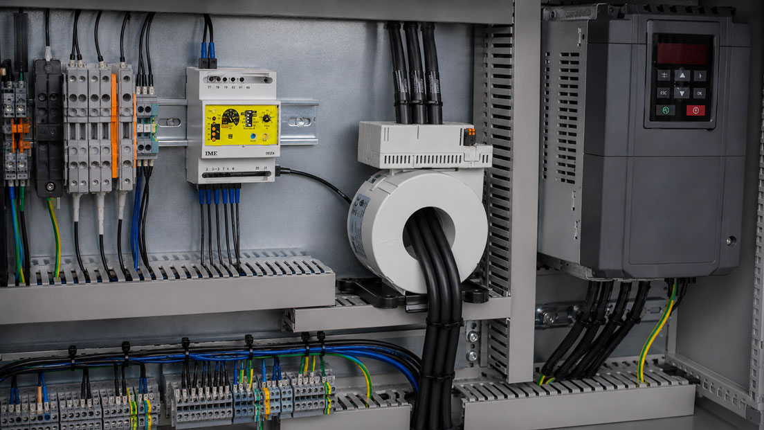
During normal operation, frequency converters generate leakage currents that flow back to the power supply through protective conductors, motor-cable shields and earthed system components. The causes include EMC filters, the capacitance of long shielded motor cables and the steep voltage switching edges at the converter output.
A residual-current relay may detect these operational currents as an exceeded threshold. However, this does not automatically mean that a dangerous insulation fault is present. At the same time, recurring tripping must not simply be suppressed by selecting a higher response value or an arbitrary filter. The actual current waveform, frequency and cause must first be determined.
The correct selection of the relay and core-balance current transformer is particularly important. A device designed for 50 or 60 Hz and Type A residual currents may be unsuitable for a circuit containing smooth DC components and high-frequency components. A suitable Type B version is required for all-current-sensitive applications.
Suitable devices can be found in the ICS category Limit-Signal Transmitters and Residual-Current Relays. Additional panel-mounted measuring and monitoring equipment is grouped under Measuring Instruments for Control-Panel Construction.
Table of Contents
- How does residual-current monitoring work?
- Distinguishing between residual-current relays and residual-current devices
- Distinguishing operational leakage current from an insulation fault
- Why do frequency converters generate leakage currents?
- Why is the frequency spectrum decisive?
- Correctly distinguishing between Types A, F, B and B+
- Correctly installing the core-balance current transformer
- Correctly accounting for the motor cable and cable shield
- Using harmonic filters appropriately
- Defining the response value and delay
- Planning trend monitoring and the alarm strategy
- Systematic diagnosis following a trip
- Insulation testing on the frequency-converter circuit
- Practical example: Tripping when the drive is enabled
- Typical errors in residual-current monitoring
- Which products and solutions are suitable?
- Conclusion
- Frequently asked questions
How does residual-current monitoring work?
A core-balance current transformer jointly measures all active conductors of a circuit. For a three-phase load, L1, L2 and L3 are normally routed through the transformer. If a neutral conductor is present, it must also be routed through the same transformer.
Under ideal fault-free conditions, the vector sum of the currents is zero:
IΔ = IL1 + IL2 + IL3 + IN = 0
If part of the current returns through the protective conductor, motor-cable shield, machine housing or earth, this portion is missing from the sum of the active conductors. The core-balance current transformer then detects a residual current.
The connected relay compares the measured value with the configured threshold. Depending on the version, it can:
- issue a pre-alarm,
- switch an alarm contact,
- transmit a signal to the PLC,
- disconnect the circuit through an external switching device,
- display the current residual current,
- detect an interruption in the connection to the core-balance current transformer.
The protective conductor must not be routed through the core-balance current transformer. Otherwise, the current returning through the protective conductor would be partially compensated and the actual residual current would not be measured correctly.
Distinguishing between residual-current relays and residual-current devices
A residual-current relay, also known as a residual-current monitor, monitors the residual current and provides an alarm or switching signal. It does not automatically have its own power-switching capability.
A residual-current device, or RCD, automatically disconnects the monitored circuit when its tripping conditions are reached. Its protective function, disconnection time and residual-current type are defined by the applicable product and application standards.
A residual-current relay must therefore not automatically be used as a substitute for a required residual-current protective device. For a disconnection function, the relay, tripping chain, circuit breaker, wiring and power supply must, among other factors, be assessed together.
Devices with a harmonic filter or an intentionally delayed response may be suitable for condition monitoring and system or fire protection. However, a response value of 30 mA alone does not make them suitable for personal protection.
Distinguishing operational leakage current from an insulation fault
Leakage current may be inherent in the design and occur during normal operation. Fault current, by contrast, results from an unintended insulation fault or an incorrect connection to earth.
| Characteristic | Operational leakage current | Possible insulation fault |
|---|---|---|
| Occurrence | Reproducible when the converter is switched on or enabled | Often new, increasing or irregular |
| Dependency | Depends on switching frequency, motor-cable length, EMC filter and number of converters | Depends on moisture, temperature, movement or damaged insulation |
| Frequency components | Often contains high-frequency components caused by PWM switching edges | Depending on the fault location, 50/60 Hz, DC components or mixed frequencies |
| Trend | Often a stable base level with brief switching peaks | May increase over days or weeks |
| Response to cable changes | Changes significantly with cable length and shield capacitance | Remains present or is concentrated on a particular load |
The distinction cannot be made solely on the basis of magnitude. Even a relatively high current may be inherent in the design, while a small but continuously increasing residual current may indicate the beginning of insulation deterioration.
Why do frequency converters generate leakage currents?
EMC filters
Line-side EMC filters contain capacitors between the active conductors and the protective conductor. A defined current flows to earth through these so-called Y capacitors even during normal operation.
If several frequency converters are operated downstream of a common residual-current relay, their leakage currents are added together. A circuit that operates without problems with a single converter may therefore exceed the threshold after the system is expanded.
Capacitance of the shielded motor cable
Electrical capacitance exists between the motor conductors and the earthed cable shield. In simplified terms, the current through this capacitance depends on the capacitance and the rate of voltage change:
i = C × du/dt
Frequency converters generate very steep voltage switching edges. As the cable length increases, the total capacitance and usually the high-frequency leakage current also increase.
Motor and machine design
Winding capacitances, motor bearings, motor filters, the earthing system and metallic machine structures also influence the return current. Moisture or contamination inside the motor can additionally cause a genuine insulation fault.
Switching operations
Brief leakage-current peaks may occur when the converter is switched on, an EMC filter is connected or the output stage is enabled. A relay without a delay may respond to these brief events even though the steady-state value is subsequently significantly lower.
Why is the frequency spectrum decisive?
A frequency-converter circuit does not generate a purely sinusoidal 50 Hz residual-current waveform. Depending on the line rectifier, DC link, output stage and filtering, the following may occur:
- sinusoidal alternating currents at the line frequency,
- pulsating DC residual currents,
- smooth DC components,
- mixed frequencies from the line and output frequencies,
- switching-frequency components in the kilohertz range,
- brief high-frequency impulses.
A relay with an operating frequency range of, for example, 47 to 63 Hz primarily assesses components at the line frequency. Depending on the device, a high-frequency leakage current may be strongly attenuated, assessed incorrectly or not detected at all.
Conversely, a broadband device may fully detect high operational frequency components and therefore indicate a higher RMS value than a frequency-selective relay.
When comparing devices, the following must therefore always be checked:
- detectable residual-current waveforms,
- lower and upper measuring frequency,
- frequency weighting or filter characteristic,
- peak-value or RMS-value evaluation,
- behaviour with smooth DC components,
- response to switch-on impulses.
Correctly distinguishing between Types A, F, B and B+
| Version | Typical detection | Assessment for frequency converters |
|---|---|---|
| Type A | Sinusoidal AC and pulsating DC residual currents | Suitable only if impermissible smooth DC components or undetected frequencies cannot occur |
| Type F | Additionally detects mixed frequencies from certain single-phase electronic loads | May be suitable for single-phase frequency converters; does not generally replace Type B |
| Type B | AC, pulsating and smooth DC residual currents as well as defined frequency components | Required for many three-phase converter and rectifier applications |
| Type B+ | Extended frequency weighting and, depending on the device, an additional fire-protection range | Device- and application-specific; not equivalent to every Type B monitor |
The designation must correspond to the specific device function. The type classifications of a residual-current protective device must not be transferred to every residual-current relay without verification.
In a three-phase frequency converter, smooth DC components may occur under fault conditions. This can impair the detection capability of an unsuitable Type A device. For such circuits, all-current-sensitive monitoring using a confirmed Type B version must be provided.
Correctly installing the core-balance current transformer
Correct installation of the core-balance current transformer is just as important as selecting the relay.
- Route all active conductors of the monitored circuit through the same core.
- If a neutral conductor is present, also route it through the core.
- Do not route the protective conductor or equipotential-bonding conductor through the core.
- Do not return any active conductors outside the transformer.
- Do not jointly monitor conductors from different circuits.
- Route the conductors through the centre of the transformer and bundle them as evenly as possible.
- Select a sufficiently large internal diameter without crushing or sharply bending the cables.
- Route the transformer connection cable separately from power-carrying converter cables.
- Observe the specified maximum cable length between the transformer and relay.
- Do not install the transformer directly next to strong magnetic fields or power contactors.
With very high load currents, asymmetrical conductor positions and magnetic stray fields can generate an apparent residual current. A sufficiently large transformer and symmetrical conductor routing reduce this effect.
Split-core current transformers can be used for retrofits. Their mating surfaces must close cleanly and must not be held open by dust, cable remnants or mechanical stress.
Correctly accounting for the motor cable and cable shield
To monitor a complete frequency-converter outgoing circuit, the core-balance current transformer is generally installed on the line side of the converter. All active supply conductors are measured together at this point.
The protective conductor and motor-cable shield are routed outside the core-balance current transformer. In accordance with the EMC concept, the cable shield should be connected over a large surface area, preferably using a 360° shield connection.
If a fully shielded motor cable, including its shield, is routed through a core-balance current transformer, the current returning through the shield may partially compensate the measurement. The relevant residual current may then not be fully detected.
Measurement on the converter output side is technically more demanding. Pulse-width-modulated voltages containing high-frequency components are present there. The relay, transformer and measuring method must be expressly suitable for this application.
Depending on the converter manufacturer, the following measures may help reduce high operational leakage currents:
- shorter motor cables,
- suitable output reactors,
- du/dt filters,
- sine-wave filters,
- an adapted switching frequency,
- separating several converters into different monitoring circuits.
EMC filters or shield connections must not be removed without the manufacturer’s approval. Doing so may impair EMC compliance, operational safety and protective measures.
Using harmonic filters appropriately
An integrated harmonic or high-frequency filter can attenuate operational frequency components. As a result, the relay responds more strongly to relevant low-frequency fault currents and less strongly to high-frequency converter currents.
However, a filter is not a universal solution. It may also suppress residual-current components that are relevant to the selected protective function.
Before activating a filter, the following must be clarified:
- which frequencies are attenuated,
- which frequencies continue to be assessed,
- whether the filter is permanently active or can be deactivated,
- whether the device is approved for the intended protective function with the filter activated,
- whether a high-frequency insulation fault will still be detected.
For relays that are expressly not intended for personal protection, a filter may be useful for system monitoring and preventive maintenance. However, it must not replace a required residual-current protective device.
Defining the response value and delay
The threshold must neither be set universally to 30 mA nor simply adjusted to the highest possible value. It must be derived from the protection and monitoring concept.
The following factors must be considered:
- maximum operational leakage current,
- number of frequency converters operating simultaneously,
- motor-cable length and shield capacitance,
- switching frequency and operating condition,
- measurement uncertainty of the relay and core-balance current transformer,
- permissible fault current of the system,
- required advance warning time,
- upstream protective devices and selectivity,
- required disconnection time.
A time delay can bridge brief switch-on and enabling peaks. However, it must not allow a dangerous fault current to remain present for too long.
For condition monitoring alone, a two-stage strategy is often useful:
- Pre-alarm: indicates a detectable deterioration and enables planned maintenance.
- Alarm or disconnection: responds to a higher or longer-lasting residual current.
The specific values must be defined and documented on the basis of measurements under all relevant operating conditions.
Planning trend monitoring and the alarm strategy
A single threshold only indicates whether the current value is above or below a defined limit. For preventive maintenance, the trend over time is often more informative.
A suitable trend can reveal:
- gradual ageing of the motor insulation,
- moisture ingress following shutdown periods,
- differences between a cold and warm motor,
- changes after replacing a cable,
- effects of a changed switching frequency,
- additional leakage currents after a system expansion.
A reference condition should be recorded during commissioning. This includes residual-current values with:
- the converter switched on but not enabled,
- the output stage enabled,
- low and high motor speed,
- partial and full load,
- a cold and operationally warm drive,
- other converters operating simultaneously.
Systematic diagnosis following a trip
- Clarify the function: Check whether the relay only signals or disconnects through an external switching device.
- Determine the timing: Establish whether tripping occurs when the power supply is switched on, when the converter is enabled, during operation or during shutdown.
- Check the relay data: Document the residual-current type, frequency range, filter, response value and delay.
- Check the transformer wiring: All active conductors must pass through the same core; PE and the shield remain outside.
- Measure the base level: Compare the residual current with the converter stopped and running.
- Record peaks: Use a sufficiently broadband measuring instrument with maximum-value or recording functionality.
- Separate outgoing circuits: Switch on several converters one after another and determine the contribution of each drive.
- Check the motor cable: Inspect its length, shield connection, damage and the permissible length specified by the converter manufacturer.
- Check the filters: Inspect external and internal EMC filters and verify their correct connection.
- Compare parameters: Investigate the effects of the switching frequency and output filters in accordance with the manufacturer’s specifications.
- Check the insulation: Test the motor and cable correctly and separately from the frequency converter.
- Document the trend: Compare measured values before and after every modification.
The threshold should only be increased after an insulation fault has been ruled out and the normal leakage current has been determined under the least favourable operating conditions.
Insulation testing on the frequency-converter circuit
An insulation measurement must not be performed without verification through the connected frequency converter. The test voltage may damage power electronics, EMC filters and surge-protection components.
For testing, the motor cable and motor are disconnected from the converter in accordance with the manufacturer’s specifications. The individual components can then be checked using a suitable test voltage.
The following should be checked in particular:
- motor windings against the housing,
- motor cable against the protective conductor or shield,
- moisture inside the terminal box,
- mechanical cable damage,
- contamination and conductive deposits,
- incorrect connection or shield terminals.
A good DC insulation resistance does not rule out every high-frequency leakage-current cause. Capacitive operational currents are only partly considered by a conventional insulation measurement.
Practical example: Tripping when the drive is enabled
A machine has a three-phase frequency converter with an EMC filter and a 45 m shielded motor cable. A Type A residual-current relay monitors the complete drive circuit.
With the converter switched on but the motor not enabled, the system operates without a fault. As soon as the output stage is enabled, the relay intermittently disconnects the connected circuit breaker.
The investigation reveals:
- All three phase conductors are correctly routed through the core-balance current transformer.
- The protective conductor is located outside the transformer.
- The steady-state residual current is below the configured threshold.
- However, brief high-frequency current peaks occur when the drive is enabled.
- The magnitude changes with the converter switching frequency.
- The motor and cable have an acceptable insulation resistance.
- The existing Type A relay is not suitable for the smooth DC and frequency components that occur.
The relay is replaced by an all-current-sensitive Type B residual-current relay with a suitable core-balance current transformer. The transformer remains on the line side of the frequency converter. The response value, pre-alarm and delay are defined on the basis of the measured operational values and the protection concept.
It is also checked whether a du/dt or sine-wave filter approved by the converter manufacturer can reduce the leakage current of the long motor cable. The modification eliminates the nuisance tripping without abandoning monitoring for a genuine insulation fault.
Typical errors in residual-current monitoring
| Error | Possible consequence | Suitable corrective action |
|---|---|---|
| Type A relay used universally for every frequency converter | Smooth DC or mixed-frequency currents are not assessed correctly | Check the residual-current waveform and required device type |
| Protective conductor routed through the core-balance current transformer | Fault current is partially compensated | Route only active conductors through the core |
| Neutral conductor routed outside the transformer | Operating current is measured as residual current | Monitor all active conductors together |
| Complete shielded motor cable routed through the transformer | Shield current may distort the measurement | Preferably install the transformer on the converter line side |
| Several circuits routed jointly through one core | Currents may compensate one another | Clearly monitor each outgoing circuit that must be assessed |
| Threshold increased without prior measurement | A genuine insulation fault is detected too late | Analyse the operational current and cause of the fault first |
| Harmonic filter activated without verification | Relevant residual-current components are filtered out | Check the filter characteristic and intended protective function |
| No delay for brief switching peaks | Nuisance tripping during switch-on or enabling | Configure only a permissible, project-specific delay |
| Very long motor connection without an output filter | High capacitive leakage currents | Coordinate the cable length and filter concept with the converter manufacturer |
| Insulation test performed through the connected converter | Damage to the power electronics | Correctly disconnect the motor and cable before testing |
| Residual-current relay treated as an automatic substitute for an RCD | The protective function and disconnection conditions have not been verified | Assess the complete protection and tripping chain in accordance with the applicable standards |
Which products and solutions are suitable?
Delta D2-B – all-current-sensitive Type B residual-current relay
The Delta D2-B is a Type B residual-current relay for circuits in which smooth DC components may occur in addition to sinusoidal and pulsating residual currents.
It is therefore particularly suitable for applications involving frequency converters, rectifiers and other power electronics. The device has a display for the current residual current as well as separate pre-alarm and alarm functions.
The response value and delay time are adjustable. The specially designed Type B core-balance current transformers are used for measurement.
Core-balance current transformers for Delta D2-B
The appropriate Type B core-balance current transformers are available with different internal diameters. This allows both compact machine circuits and larger conductor cross-sections to be monitored.
The core must be compatible with the D2-B version. Conventional core-balance current transformers for Type A relays must not be combined with the all-current-sensitive relay without express approval.
Delta RD2E2 or Delta 72-F
The Delta RD2E2 is designed for demanding industrial applications and distorted current waveforms. It has a fixed harmonic filter and can therefore reduce operational frequency components from converters and variable-speed drives.
Because of this filtering, the version is expressly not intended for personal protection. It is primarily suitable for system monitoring, alarm signalling and a project-specific disconnection function.
Delta D2-L and D2-S
The Delta D2-L and the Delta D2-S are compact residual-current relays for DIN-rail mounting. They have adjustable thresholds and integrated harmonic filters.
These Type A versions may only be used if the possible residual-current waveforms and DC components in the system correspond to their specification. A suitable Type B version is required instead for circuits in which smooth DC residual currents may occur.
DEL and TDS core-balance current transformers
The DEL and TDS core-balance current transformers are available in different sizes for residual-current monitoring.
Closed-core transformers provide a compact and robust solution for new installations. For retrofits, split-core DEL-A current transformers can be installed without completely disconnecting the existing conductors.
ICS Schneider Messtechnik provides support in selecting residual-current relays and core-balance current transformers and in assessing the residual-current waveform, frequency range, cable diameter, response value, delay and alarm strategy.
Conclusion
Frequency converters generate operational leakage currents due to EMC filters, steep switching edges and shielded motor cables. These currents may trip an incorrectly selected or overly sensitive residual-current relay.
A trip must neither automatically be interpreted as an insulation fault nor suppressed through a universal increase in the threshold. The decisive factors are the magnitude, frequency spectrum, time characteristic and dependency on converter operation.
All-current-sensitive Type B monitoring is required in circuits in which smooth DC residual currents may occur. A Type A device or a relay limited to 50/60 Hz cannot fully assess the residual-current waveforms that may be present.
All active conductors must be routed together through the core-balance current transformer. The protective conductor and cable shield remain outside. For unambiguous monitoring, the transformer is usually installed on the line side of the frequency converter.
Harmonic filters and response delays can reduce nuisance tripping but may only be used within the confirmed device and protective function. A filtered residual-current relay is not automatically suitable for personal protection.
The best solution combines technically suitable device selection with a documented baseline measurement, pre-alarm, trend monitoring and systematic diagnosis of the complete drive circuit.
Frequently asked questions about residual-current monitoring with frequency converters
Why does the relay only trip when the motor starts?
When the converter output stage is enabled, pulse-width-modulated voltages with steep switching edges are generated. This causes additional capacitive leakage currents to flow through the motor cable and motor.
Is every leakage current an insulation fault?
No. EMC filters and cable capacitances also generate leakage currents during fault-free operation. However, a new, increasing or strongly asymmetrical current may indicate an insulation fault.
Can the response value simply be increased?
Only after an insulation fault has been ruled out and the maximum operational leakage current has been measured. The setting must still correspond to the required protective function.
Which relay type is required for a frequency converter?
This depends on the converter topology and the possible residual-current waveforms. A suitable Type B version is generally required for three-phase converters in which smooth DC residual currents may occur.
Is a Type A relay with a harmonic filter sufficient?
Not if smooth DC residual currents may occur. The filter changes the frequency weighting but does not automatically extend the residual-current detection capability to Type B.
Where is the core-balance current transformer installed?
For monitoring the complete drive circuit, it is normally installed on the line side of the frequency converter. All active supply conductors are routed together through the core.
May the protective conductor be routed through the core-balance current transformer?
No. The protective conductor must run outside the transformer so that fault or leakage current returning through it is detected as a residual current.
Must the neutral conductor be routed through the transformer?
Yes, provided that it belongs to the monitored circuit. All active outgoing and return conductors must be measured together.
Why does a long motor cable increase the leakage current?
As the cable length increases, the capacitance between the motor conductors and the earthed shield also increases. The steep converter voltages drive high-frequency currents to earth through this capacitance.
Does a sine-wave filter help prevent nuisance tripping?
A suitable sine-wave or du/dt filter can reduce the voltage switching edges and therefore the capacitive leakage currents. The filter must be matched to the frequency converter, motor and cable.
May a residual-current relay replace a required RCD?
Not automatically. The relay initially only monitors and signals. The complete tripping chain and the required protective conditions must be verified for a disconnection function.
How can gradual insulation deterioration be detected?
By regularly recording the residual current under comparable operating conditions. A base level that increases over the long term is often more informative than a single threshold exceedance.