


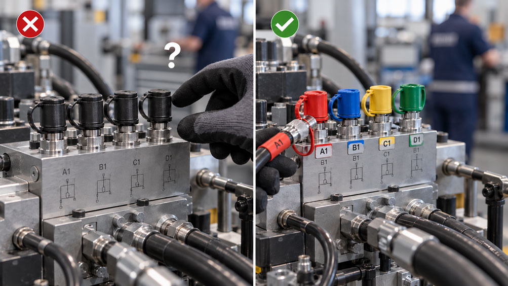
Several MINIMESS service points are located close together on a hydraulic power unit. Maintenance personnel use these connections to check the pump pressure, the pressure of an auxiliary drive and the condition of a separate cooling circuit.
All test couplings look similar. The protective caps are uniformly black, and the original measuring point numbers are only partially legible.
During a maintenance inspection, the wrong connection is accidentally selected. Although the pressure gauge used has a suitable measuring range, it is unclear which pressure circuit and medium are present.
Additional color coding can reduce such mix-ups. Colored protective caps, marking rings and clearly labeled measuring points make identification easier, even in confined installation spaces.
However, it is essential that each color is always linked to a unique measuring point ID, the medium and the permissible pressure conditions.
This article explains how MINIMESS service points can be systematically identified, which technical limitations apply and how a clear identification system can be integrated into hydraulic servicing and maintenance.
Table of Contents
- Measurement Tasks and Risk of Confusion
- Operating Principle of MINIMESS Test Points
- Typical Mix-Ups During Maintenance
- Combining Color Coding with Measuring Point IDs
- Distinguishing Pressure Circuits and Media
- Establishing a Company-Specific Color-Coding System
- Permanent Labels and Identification Tags
- Practical Example: Correctly Identifying Three Pressure Circuits
- Coupling Series 1215, 1615, 1620 and 1604
- Colored Protective Caps and Marking Rings
- Clearly Identifying Test Hoses
- Sealing Materials and Media Compatibility
- Operating Pressure and Pressure Peaks
- Considering Temperature Limits
- Adapters and Different Connections
- Safe Procedures for Connecting Couplings
- Retrofitting Identification Systems to Existing Installations
- Measuring Point Plans and Digital Documentation
- Cleanliness and Protection of Couplings
- Inspection and Commissioning Procedure
- Typical Errors and Troubleshooting
- Suitable ICS Products
- Conclusion
- Frequently Asked Questions
1. Measurement Tasks and Risk of Confusion
MINIMESS service points enable temporary connections between measuring instruments and hydraulic or other suitable fluid systems.
Particularly on large hydraulic power units, several connections are often located on a single valve block.
Clear identification is intended to prevent technicians from selecting the wrong pressure circuit or connecting an unsuitable test hose during maintenance.
2. Operating Principle of MINIMESS Test Points
A conventional MINIMESS test point contains a mechanically operated shut-off element.
When a suitable mating coupling is connected, the measuring passage opens. The valve closes again when the connection is disconnected.
Original MINIMESS test points are also designed for appropriate maintenance operations under system pressure. However, specific approval depends on the coupling series, configuration and connection conditions.
The protective cap primarily protects against contamination and mechanical damage. It must not be regarded as an independent pressure-retaining safety shut-off device.
3. Typical Mix-Ups During Maintenance
The risk of confusion is particularly high when connections look identical, measuring point numbers are illegible or several media circuits are present.
Typical errors include connecting to the wrong pressure circuit, using an unsuitable hose or confusing pressure measurement connections with filling connections.
Different coupling series may also look similar externally, even though their connection geometries are incompatible.
4. Combining Color Coding with Measuring Point IDs
Color enables quick visual identification. However, it is not sufficient for unambiguous technical identification.
Each service point should also have a permanently legible identifier, such as P-A01 or P-B02.
The color identifies the group defined by the company, while the number uniquely identifies the individual measuring point.
The system must remain understandable even in the presence of contamination, poor lighting and impaired color vision.
5. Distinguishing Pressure Circuits and Media
An identification system can distinguish between hydraulic pressure circuits, different operating media or various service functions.
These characteristics should not be mixed indiscriminately.
A clear separation between hydraulic oil, water-glycol mixtures and other media is particularly important, as different seals and test hoses may be required.
A green, blue or red service point does not have a specific pressure rating simply because of its color.
6. Establishing a Company-Specific Color-Coding System
A simple color scheme can be defined for a new installation. It is important that the assignment is documented and consistently maintained.
| Color | Pressure Circuit | Additional Identification |
|---|---|---|
| Red | Main hydraulic circuit A | A01–A04 / Hydraulic oil |
| Blue | Auxiliary hydraulic circuit B | B01–B04 / Hydraulic oil |
| Yellow | Separate media circuit C | C01–C04 / Water-glycol |
The colors are freely selected examples only. They do not represent standardized MINIMESS color assignments.
Existing plant identification systems, safety colors and company standards must be considered when defining the scheme. Color coding of a pressure circuit must not be confused with approval or hazard identification.
7. Permanent Labels and Identification Tags
A suitable marking should be resistant to oil, cleaning agents, temperature and mechanical stress.
Possible options include engraved tags, suitable cable markers or special identification tags located directly next to the test point.
At least the following information is useful for clear identification:
- Measuring point ID.
- Pressure circuit or system function.
- Medium.
- Relevant permissible pressure range.
- Reference to the associated measuring point plan, if required.
For very small protective caps, the complete information can be displayed on a permanently mounted tag immediately next to the connection.
8. Practical Example: Correctly Identifying Three Pressure Circuits
A hypothetical hydraulic power unit has twelve MINIMESS service points distributed across three different circuits, each containing four measuring points.
The identification system is intended to facilitate circuit assignment and support the selection of suitable test hoses.
8.1 Initial Data
- Main circuit A: 300 bar operating pressure, possible pressure peaks up to 340 bar.
- Auxiliary circuit B: 120 bar operating pressure, possible pressure peaks up to 150 bar.
- Media circuit C: 20 bar operating pressure, possible pressure peaks up to 30 bar.
- Circuits A and B use hydraulic oil.
- Circuit C uses a water-glycol mixture.
- Hypothetical hoses with permissible operating pressures of 315 bar and 400 bar under their respective specified conditions are available for selection.
All values are freely selected calculation assumptions. They do not replace an application-specific pressure and safety assessment.
8.2 Assigning Measuring Points
The twelve measuring points are clearly divided:
12 measuring points / 3 circuits = 4 measuring points per circuit
For example, IDs A01 to A04 are assigned to the main circuit.
Correspondingly, the other circuits receive identifiers B01 to B04 and C01 to C04.
8.3 Checking Pressure Suitability
Pressure peaks of up to 340 bar are assumed for main circuit A.
A test hose with a maximum permissible operating pressure of 315 bar would not cover this pressure:
340 bar > 315 bar
The ratio is:
340 / 315 · 100% = 107.9%
The assumed pressure therefore already exceeds the rated value of this hose.
For a hose with a permissible operating pressure of 400 bar, the calculated result is:
400 – 340 = 60 bar margin below the rated pressure
This only confirms that this individual pressure condition is met. Temperature, pressure impulses, medium, connection fittings and complete pressure approval must still be checked.
8.4 Summary of Results
| Circuit | Measuring Points | Medium | Operating Pressure | Assumed Pressure Peak |
|---|---|---|---|---|
| A – Red | A01–A04 | Hydraulic oil | 300 bar | 340 bar |
| B – Blue | B01–B04 | Hydraulic oil | 120 bar | 150 bar |
| C – Yellow | C01–C04 | Water-glycol | 20 bar | 30 bar |
| Test hose 315 bar | Unsuitable for A | Additional media compatibility check | 315 bar rated pressure | 340 bar exceeds this value |
| Test hose 400 bar | Pressure criterion for A mathematically met | Additional media compatibility check | 400 bar rated pressure | Further conditions must be met |
8.5 Interpreting the Results
The colored caps make it easier to distinguish between the three circuits. The IDs also enable unique identification of each individual measuring point.
However, the comparison of pressure values demonstrates that identification does not replace verification of hose suitability.
A hose with matching color coding may still be technically unsuitable. All components of the measurement chain and their actual permissible operating conditions are decisive.
9. Coupling Series 1215, 1615, 1620 and 1604
The conventional MINIMESS series differ particularly in coupling geometry, nominal diameter and available configurations.
Series 1620 has an M16 × 2 thread on the coupling side. Series 1615 uses M16 × 1.5.
Series 1215 is designed as a particularly compact DN2 version. Series 1604, on the other hand, has the larger nominal diameter DN4.
The maximum pressure rating depends on the series and specific product. The manufacturer specifies up to 400 bar for series 1604 and up to 630 bar for corresponding DN2 series.
Colored caps must not obscure these mechanical differences.
10. Colored Protective Caps and Marking Rings
Colored plastic protective caps are a simple way to visually distinguish existing measuring points.
Additional permanent marking on the hydraulic block is useful because the protective cap is removed during measurement.
Colored rings or tags can preserve identification if a cap is lost.
All identification components must fit the specific coupling and must not interfere with its operation or sealing function.
11. Clearly Identifying Test Hoses
In addition to the test points, the test hoses themselves can also be marked.
A hose ID and suitable marking of the connections make it easier to assign hoses to specific measurement tasks.
However, color coding must not be confused with the actual approval of the hose for use.
Depending on the configuration, MINIMESS microbore hoses are available for pressure ratings of 315, 400 or 630 bar, for example.
Hose material, fittings, nominal diameter, temperature and medium determine the actual permissible use.
12. Sealing Materials and Media Compatibility
MINIMESS systems are available with different sealing materials, such as NBR, FKM or EPDM.
Suitability depends on the medium, temperature and other operating conditions.
A seal suitable for mineral oil-based hydraulic fluids is not automatically suitable for all water-glycol mixtures or other operating media.
The specific medium designation, composition and manufacturer approval should be considered during selection.
13. Operating Pressure and Pressure Peaks
The permissible pressure load of the complete measurement setup is limited by the weakest relevant component.
The test point, hose, connection fittings, adapters and measuring instrument must all be considered.
Short-term pressure peaks may also occur, significantly exceeding normal operating pressure.
The assessment must also consider the manufacturer’s specifications concerning dynamic pressure loading and intended use.
14. Considering Temperature Limits
High temperatures can affect the permissible load capacity of hoses and seals.
When used on hot hydraulic installations, the temperature limits of all components must therefore be checked.
Colored protective caps or marking rings must also have sufficient temperature resistance.
The color of a test point provides no information about its actual permissible temperature range.
15. Adapters and Different Connections
Adapters enable different connection types to be joined but may only be used where mechanical and technical compatibility has been verified.
In particular, coupling series, connection threads, sealing principle and permissible pressure must be compatible.
A thread that appears to fit must never be forced into a connection.
The fewer unnecessary adapters used, the easier it is to inspect and document the measurement setup.
16. Safe Procedures for Connecting Couplings
Before measurement, the technician must identify the measuring point using its ID and the system documentation.
The medium, expected pressure, coupling series and test hose are then checked.
Original MINIMESS connections in suitable configurations are designed for coupling under pressure. However, the actual procedure must comply with manufacturer instructions and operational safety requirements.
Particular care is required if residual pressure is trapped inside the test hose.
A test hose must never be used as an improvised connection between separate pressure or media circuits.
17. Retrofitting Identification Systems to Existing Installations
Older installations often lack clear measuring point labels.
Before applying new color coding, each measuring point must therefore be identified using the available hydraulic documentation and safe technical verification.
Unknown connections must not be assigned to a pressure circuit solely based on their physical location.
The verified assignment is then documented and permanently marked.
18. Measuring Point Plans and Digital Documentation
A measuring point plan links the identification markings to the technical information.
For example, it should contain the measuring point ID, circuit, medium, pressure range, coupling series, connection and required testing equipment.
Digital measuring point lists or QR codes can make this information easier to access.
However, essential information must remain available even when no mobile device or network connection is available.
19. Cleanliness and Protection of Couplings
Protective caps reduce the ingress of dust, moisture and other contaminants.
Before connecting, the coupling area and mating connection should be inspected for contamination and damage.
After completing service work, connections are cleaned and protected again according to the specified procedure.
A damaged or missing protective cap should be replaced without losing the clear identification of the measuring point.
20. Inspection and Commissioning Procedure
The following procedure is recommended when introducing an identification system:
- Record all MINIMESS service points.
- Assign measuring points to the actual pressure circuits.
- Document media, operating pressure and pressure peaks.
- Identify coupling series and connection geometry.
- Coordinate the color scheme with existing plant identification systems.
- Assign unique measuring point IDs.
- Install suitable protective caps, marking rings and identification tags.
- Assign test hoses and measuring instruments according to their suitability.
- Update the measuring point plan and instruct personnel.
- Verify the markings and measuring point assignments during acceptance inspection.
21. Typical Errors and Troubleshooting
Color matches, but the hose does not fit: Check the coupling series, thread and connection type.
Measured value comes from the wrong pressure circuit: Compare the measuring point ID with the hydraulic diagram.
Protective cap missing: Inspect the coupling for contamination and damage, then install a suitable replacement.
Risk of confusion despite color coding: Use additional numbering or clear labeling.
Medium unknown: Do not approve the service point based on its color marking. Verify the actual medium assignment.
Hose unsuitable for the pressure: Do not perform the measurement. Select a measurement setup suitable for all operating conditions.
22. Suitable ICS Products
ICS Schneider Messtechnik offers various MINIMESS test points, microbore hoses and accessories for industrial service and pressure measurement applications.
| Product | Technical Features | Typical Application |
|---|---|---|
| MINIMESS 1620 | DN2, M16 × 2, up to 630 bar depending on configuration | Standard service points in hydraulic systems |
| MINIMESS 1615 | DN2, M16 × 1.5, up to 630 bar depending on configuration | Measuring points with the corresponding coupling geometry |
| MINIMESS 1215 | Compact DN2 version, up to 630 bar depending on configuration | Hydraulic blocks with limited installation space |
| MINIMESS 1604 | DN4, up to 400 bar according to the manufacturer | Filling, draining and service operations requiring higher flow rates |
| MINIMESS hoses | DN2/DN4, various pressure ratings, connections and hose materials | Connection to pressure gauges and pressure sensors |
22.1 MINIMESS 1620
The MINIMESS 1620 series has an M16 × 2 coupling thread and is one of the commonly used configurations for industrial pressure measuring points.
With suitable components, it enables the connection of pressure gauges, pressure sensors and test hoses.
Depending on the configuration, protective caps and additional identification options are available.
MINIMESS 1620 – Product Information
22.2 MINIMESS 1615
Series 1615 uses M16 × 1.5 on the coupling side and is available with different male connection threads and sealing materials.
Clear identification is particularly important when 1620 test points are also installed in the same system.
MINIMESS 1615 – Product Information
22.3 MINIMESS 1215
The compact 1215 series is suitable for confined installation spaces, for example on hydraulic and valve blocks.
Protective caps, coupling geometry and connection variants must match the specific configuration.
MINIMESS 1215 – Product Information
22.4 MINIMESS 1604
The 1604 series has the larger nominal diameter DN4 and is particularly useful for service operations requiring higher flow rates.
The manufacturer specifies a maximum operating pressure of up to 400 bar for this series. The specific product variant and all other operating limits must be verified.
MINIMESS 1604 – Product Information
22.5 MINIMESS Hoses and Identification Accessories
MINIMESS hoses are available with different connection fittings, nominal diameters and pressure ratings.
Suitable protective caps and colored rings can form part of a company-specific identification system.
ICS supports the selection and configuration of couplings, hoses, adapters and suitable measuring instruments for the respective application.
MINIMESS Hoses – Product Information
Additional MINIMESS Products at ICS Schneider Messtechnik
23. Conclusion
A systematic color-coding system can improve identification on hydraulic installations and reduce the risk of confusion during maintenance work.
Combining colored protective caps, permanently legible measuring point IDs and an up-to-date measuring point plan is particularly useful.
Colors must be clearly defined within the company. They do not replace identification of the pressure circuit or verification of the technical connection conditions.
Even when connections have matching colors, the coupling series, pressure rating, medium, temperature, sealing material and test hose must be compatible.
The most important rule is: Color makes identification easier – safe assignment requires clear measuring point identification and technical verification.
24. Frequently Asked Questions
24.1 Why Should MINIMESS Service Points Be Color-Coded?
Colors make it easier to visually distinguish different pressure circuits and can reduce mix-ups during maintenance.
24.2 Are There Standardized Colors for MINIMESS Pressure Circuits?
The colors used in this article are not mandatory MINIMESS color specifications. The assignments must be clearly defined within the company.
24.3 Is a Colored Protective Cap Sufficient?
No. The measuring point should also be identifiable through a permanent marking.
24.4 How Can Several Hydraulic Circuits Be Distinguished?
By combining color coding, circuit designation and measuring point ID, for example A01, B01 or C01.
24.5 Can Different Media Use the Same Coupling Series?
In principle, yes, provided the respective configuration is suitable. However, mixing different media must be prevented.
24.6 Can a Hose Be Selected Based on Its Color Alone?
No. Pressure rating, medium, temperature, connection and sealing materials must be checked.
24.7 What Pressure Rating Does MINIMESS 1620 Have?
Suitable configurations are available for operating pressures up to 630 bar. The actual product configuration is decisive.
24.8 Are MINIMESS 1615 and 1620 Compatible?
No, not directly. Their coupling threads differ: M16 × 1.5 and M16 × 2.
24.9 What Is MINIMESS 1215 Suitable For?
The compact DN2 version is particularly suitable for measuring points with limited installation space.
24.10 What Makes MINIMESS 1604 Different?
This series has DN4 and is intended for applications requiring higher flow rates. The manufacturer specifies operating pressures up to 400 bar.
24.11 What Is the Purpose of the Protective Cap?
It protects the coupling side against dirt, moisture and damage. It does not replace the integrated shut-off element.
24.12 Can MINIMESS Test Points Be Connected Under Pressure?
Suitable original MINIMESS systems are designed for this purpose. Permissible procedures depend on manufacturer instructions and operating conditions.
24.13 What Must Be Considered if a Test Hose Contains Residual Pressure?
Trapped pressure must be taken into account and, where necessary, released according to the specified safe procedure.
24.14 Why Must Sealing Materials Be Checked?
NBR, FKM, EPDM and other materials have different media and temperature compatibility characteristics.
24.15 Can Existing Hydraulic Installations Be Retrofitted with Color Coding?
Yes. However, all connections must first be clearly identified and matched to their actual pressure circuits.
24.16 Are QR Codes Useful for MINIMESS Measuring Points?
They can provide access to technical documentation and measuring point information. However, basic identification should remain legible without a QR code.
24.17 What Errors Can Result from Incorrect Assignment?
Possible consequences include incorrect measurement results, unsuitable hose connections, mixing of media and hazardous pressure loads.
24.18 What Information Does ICS Need to Prepare a Quotation?
The required information includes the number of service points, coupling series, connection threads, media, operating pressure, pressure peaks, temperature, desired identification system and required test hoses.