


 Datasheet
The Modbus 4-Channel Al Modul provides four fully isolated, independently configurable inputs. Each input can be configured as either a current input or a voltage input. Various filter functions can be used to suppress interferences.
All parameters can be set via the Modbus RTU interface and via a programming socket behind the front panel. A free PC configuration software also offers extended setting options and extensive diagnostic functions during operation. A subset of the most common settings is also available via DIP switches.
The 5 port isolation ensures reliable decoupling of the inputs from each other and from the processing circuit and the power supply. Power supply and Modbus RTU are connected via the rear-mounted In-Rail-Bus connection (see Accessories).
Product line
| Device Type | Order-No. |
|---|---|
| Modbus 4 Channel AI Module, In-Rail-Bus for power supply and Modbus connection |
DMB 96200 B |
Technical Data
Input AI
| Voltage | Current | |
| Input signal | 0 to 10 V | 0 to 20 mA |
| 4 Channels, common selectable via DIP switch, individual configurable by software | ||
| Input resistance | ≥ 100 kΩ | ≤ 25 Ω |
| Overload | ≤ 30 V | ≤ 100 mA |
Modbus
| Protocol | Modbus RTU (RS485) | |
| Module addressing | 1 to 247 | |
| Response delay | 1 to 1000 ms | |
| Baud rate | 300, 600, 1200, 2400, 4800, 9600, 19200, 38400, 57600, 115200 | |
| Configuration | Parity: Even, Odd, None 2 Stop bits, None 1 Stop bit | |
| Connectivity | Up to 247 DRAGO Modbus devices without additional repeater (1/8 Load) | |
| Indication | Yellow LED on front panel | |
General Data
| Measuring error | < 0.1 % full scale |
| Temperature coefficient1) | < 100 ppm/K |
| Resolution | 14 bit |
| Test voltage | 3 kV AC, 50 Hz, 1 min., All channels against each other and against Modbus/power supply |
| Working voltage2) (Basic insulation) |
600 V AC/DC for overvoltage category II and pollution degree 2 acc. to EN 61010-1 |
| Protection against dangerous body currents1) |
Protective Separation by reinforced insulation acc. to DIN EN 61010-1 up to 300 V AC/DC for overvoltage category II and contamination class 2 between input and Modbus/power supply |
| Ambient temperature | Operation: -25 °C to +70 °C (-13 to +158 °F) Transport and storage: -40 °C to +85 °C (-40 to +185 °F) |
| Power supply | 24 V DC, voltage range 16.8 V to 31.2 V DC, max. 1.0 W |
| EMC2) | EN 61326-1 |
| Construction | 6.2 mm (0.244’’) housing, protection type: IP 20, mounting on 35 mm DIN rail acc. to EN 60715 |
| Connection Captive plus-minus clamp screws |
Wire cross-section 0.5 to 2.5 mm2 / AWG 20-14 Stripped length: 8 mm / 0.3 in Screw terminal torque 0.6 Nm / 5 lbf in Optional power connection via In-Rail-Bus (see accessories) |
| Weight | Approx. 70 g |
- Average TC related to full scale value in specified operating temperature range, reference temperature 23 °C
- For applications with high working voltages, ensure there is sufficient spacing or isolation from neighboring devices and protection against electric shocks.
- Minor deviations possible during interference
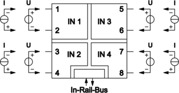
Block diagram
Dimensions
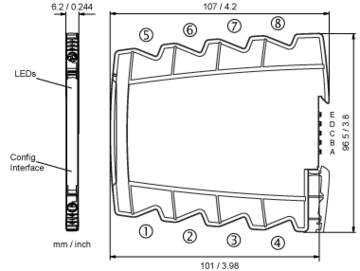
Terminal assignments
- 1+U / −I … Channel 1
- 2−U / +I
- 3+U / −I … Channel 2
- 4−U / +I
- 5+U / −I … Channel 3
- 6−U / +I
- 7+U / −I … Channel 4
- 8−U / +I
- AModbus A
- BModbus B
- C −Power supply 24 V DC
- D +Power supply 24 V DC


