


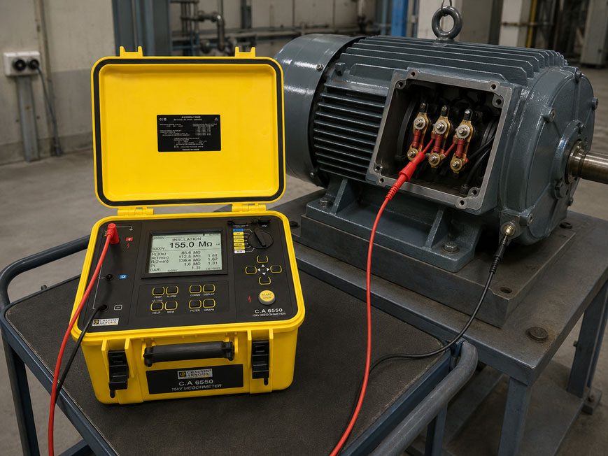
A single insulation resistance value of, for example, 500 MΩ initially only indicates the resistance of the insulation system at a specific point in time, at a specific test voltage and under the current temperature and ambient conditions.
For assessing the condition of motors, generators, transformers and other larger insulation systems, it can therefore also be useful to examine how the insulation resistance changes during a longer DC voltage test.
This is exactly where the Polarization Index PI and the Dielectric Absorption Ratio DAR come into play.
In a classic PI test, the insulation resistance after one minute is compared with the resistance after ten minutes:
PI = R10 min / R1 min
With the commonly used DAR method, the comparison is already made after 30 and 60 seconds:
DAR = R60 s / R30 s
In many intact solid insulation systems, the measured resistance increases significantly during the test period because capacitive charging and polarization currents decrease over time. Moisture, conductive contamination or other leakage paths can reduce this increase.
However, PI and DAR must not be regarded as universal pass/fail values for every item of equipment. Insulation material, machine design, temperature, test voltage, previous operating condition and manufacturer or standard requirements must all be taken into account when assessing the result.
Suitable test instruments can be found under electrical measuring and test instruments at ICS Schneider.
Table of Contents
- Why does insulation resistance change during the measurement?
- Which current components flow during an insulation test?
- What is the Polarization Index PI?
- What is DAR?
- PI and DAR in direct comparison
- How are PI and DAR values generally interpreted?
- Why should general limit values not be adopted blindly?
- PI measurement on motors and generators
- PI and DAR on transformers
- Special considerations for oil-filled transformers
- How do moisture and contamination affect PI?
- What influence does temperature have?
- Why is trend evaluation often more important than a single value?
- Selecting the correct test voltage
- Preparing the test object correctly
- Connecting a motor correctly for testing
- Connecting a transformer correctly for testing
- Why must the test times be observed exactly?
- Taking capacitive charging time into account
- Safely discharging the test object after measurement
- When is a guard connection useful?
- Practical example: PI measurement on a motor
- Practical example: deteriorating trend despite high resistance
- Typical fault patterns
- Recommended test procedure
- Suitable insulation testers from ICS Schneider
- Conclusion
- FAQ
Why does insulation resistance change during the measurement?
During an insulation test, a defined DC voltage is applied between electrically isolated parts.
For example between:
- motor winding and motor housing,
- different winding systems,
- transformer winding and earth,
- primary and secondary winding.
The insulation tester measures the flowing current and calculates:
R = U / I
Immediately after the test voltage is applied, however, this current does not consist solely of the actual permanent leakage current.
The insulation system also behaves:
- capacitively,
- dielectrically,
- time-dependently.
As a result, the total current changes during the first seconds and minutes of the measurement.
Which current components flow during an insulation test?
In simplified form, the measured total current can be divided into several components:
Itotal = Icapacitive + Iabsorption + Ileakage
Capacitive charging current
Windings, conductors and grounded housing parts form electrical capacitances relative to one another.
When the DC voltage is applied, these capacitances are initially charged.
The capacitive charging current is comparatively high immediately after the start and then decreases rapidly.
Absorption or polarization current
Polarization processes take place in the insulating material under the applied electric field.
This current component decreases more slowly than the purely capacitive charging current.
Leakage current
The remaining conduction current through or across the insulation is significantly influenced by:
- insulation condition,
- moisture,
- contamination,
- temperature,
- surface condition
.
With good insulation
the charging and absorption currents decrease significantly during the measurement.
The total current decreases and the calculated insulation resistance increases.
With significant leakage paths
the leakage current dominates instead.
The resistance may then change much less over time.
What is the Polarization Index PI?
The Polarization Index is the ratio of two insulation resistance values measured during the same continuous test.
The usual formula is:
PI = R10 min / R1 min
Example
After one minute, the measured value is:
R1 min = 500 MΩ
After ten minutes:
R10 min = 1,500 MΩ
This gives:
PI = 1,500 MΩ / 500 MΩ
therefore:
PI = 3.0
What does this value indicate?
The resistance has increased to three times its initial value during the test period.
For a suitable insulation system, such a trend generally indicates pronounced time-dependent polarization and a relatively low steady-state leakage current.
However, the final assessment must be based on the criteria applicable to the specific equipment under test.
What is DAR?
DAR stands for:
Dielectric Absorption Ratio
and is based on the same basic principle as the PI test.
However, the measurement duration is considerably shorter.
A commonly used definition is:
DAR = R60 s / R30 s
Example
After 30 seconds:
R30 s = 420 MΩ
After 60 seconds:
R60 s = 590 MΩ
This gives:
DAR = 590 / 420
or approximately:
DAR = 1.40
Advantage of DAR
The test takes only about one minute.
It is therefore well suited for:
- quick condition checks,
- repeat measurements,
- maintenance with limited time available.
Disadvantage
Because only the first 60 seconds are considered, DAR reflects longer-term polarization processes less completely than a ten-minute PI test.
PI and DAR in direct comparison
| Criterion | DAR | PI |
|---|---|---|
| Typical measurement times | 30 s and 60 s | 1 min and 10 min |
| Test duration | approx. 1 minute | 10 minutes |
| Basic principle | time-dependent resistance ratio | time-dependent resistance ratio |
| Suitable for quick testing | very good | limited |
| Long-term polarization behavior | only partially captured | captured much better |
| Temperature change during individual test | normally low | normally low |
| Trend evaluation | possible | particularly useful |
How are PI and DAR values generally interpreted?
As a general orientation, the following ranges are often stated in technical literature.
Polarization Index PI
| PI | General orientation |
|---|---|
| < 1 | abnormal or potentially problematic |
| 1 … 2 | investigate further or assess according to the application |
| 2 … 4 | good range for many solid insulation systems |
| > 4 | high ratio; consider application and insulation system |
DAR
For the ratio:
R60 s / R30 s
values above approximately:
1.3 … 1.4
are often regarded as indicating a noticeable increase in resistance.
These tables are only general guideline values. The manufacturer’s specifications, the applicable test procedure, the type of insulation system and the historical development of the specific equipment are decisive.
Why should general limit values not be adopted blindly?
A PI of:
1.2
is not automatically poor for every item of equipment.
Likewise, a PI of:
4.5
is not automatically optimal for every item of equipment.
The result depends, among other things, on
- insulation material,
- age and design,
- capacitance of the test object,
- moisture content,
- surface contamination,
- temperature,
- test voltage.
Modern insulation systems
may show different polarization behavior from older:
- resin-impregnated windings,
- paper-based systems,
- conventional varnish insulation systems.
For this reason, a single table value should never be the only basis for deciding on:
- continued operation,
- drying,
- cleaning,
- repair
.
PI measurement on motors and generators
The Polarization Index is used particularly frequently on electrical machines with larger winding insulation systems.
These include:
- motors,
- generators,
- larger drives.
Typical test
One winding or the combined windings are tested against the grounded machine housing.
The same test voltage remains applied throughout the entire ten-minute measurement.
The insulation tester stores or determines:
R1 min
and:
R10 min
.
The advantage
The measurement assesses not only the absolute insulation resistance, but also its time-dependent behavior.
For example, a winding with:
800 MΩ after 1 minute
can be assessed differently from another winding that also reaches:
800 MΩ
but has already stabilized at this value after only a few seconds.
PI and DAR on transformers
Time-dependent insulation measurements can also provide valuable additional information for transformers.
Depending on the transformer and test procedure, the following may be examined, for example:
- high-voltage winding to earth,
- low-voltage winding to earth,
- high-voltage winding to low-voltage winding.
Particularly important
A transformer consists of a complex insulation system comprising:
- windings,
- solid insulation,
- insulating liquid where applicable,
- bushings,
- core and housing.
The interpretation of a PI or DAR value must therefore be appropriate for the specific transformer design.
Special considerations for oil-filled transformers
Particular caution is required when applying generic PI limits to oil-filled transformers.
Liquid insulation shows different dielectric behavior from many solid insulation systems.
A PI close to 1
therefore does not necessarily have the same significance in such a system as it would in a conventional motor winding.
For oil-filled transformers, PI and DAR should therefore only be interpreted in accordance with:
- manufacturer specifications,
- transformer design,
- applicable test procedure,
- historical measurement values
.
The frequently quoted rule of thumb that “PI must be greater than 2” must therefore not be applied without verification to every transformer insulation system.
How do moisture and contamination affect PI?
Moisture and conductive contamination often increase leakage current.
As a result, a larger proportion of the total current remains even after a longer test duration.
Example of dry, clean insulation
After one minute:
400 MΩ
After ten minutes:
1,200 MΩ
Result:
PI = 3.0
Example of abnormal insulation
After one minute:
400 MΩ
After ten minutes:
500 MΩ
Result:
PI = 1.25
Although both tests show the same absolute resistance after one minute, their time-dependent behavior is clearly different.
This is precisely where the PI test provides additional information.
What influence does temperature have?
The absolute insulation resistance is strongly temperature-dependent.
At higher temperatures
the insulation resistance of many insulating materials is lower.
At lower temperatures
it is correspondingly higher.
Two absolute resistance values can therefore only be meaningfully compared if temperature is taken into account.
PI and DAR partially reduce this influence
Because both resistance values are recorded during the same test and within a relatively short period, the temperature of the test object normally remains approximately constant.
The ratio is therefore less temperature-sensitive than comparing two individual insulation resistance values measured on different days and at different temperatures.
However, PI and DAR are not completely independent of temperature. For reliable condition monitoring, temperature should still be documented.
Why is trend evaluation often more important than a single value?
Insulation testing becomes particularly valuable when repeat measurements are carried out under comparable conditions.
Example
| Test | R after 1 min | R after 10 min | PI |
|---|---|---|---|
| Year 1 | 1.2 GΩ | 3.6 GΩ | 3.0 |
| Year 2 | 1.0 GΩ | 2.8 GΩ | 2.8 |
| Year 3 | 750 MΩ | 1.65 GΩ | 2.2 |
| Year 4 | 520 MΩ | 780 MΩ | 1.5 |
Each individual measurement may initially still show a relatively high absolute resistance.
However, the long-term trend shows:
- decreasing insulation resistance,
- decreasing PI,
- an increasingly flatter resistance increase.
Such a development can be much more informative for maintenance than simply checking whether a single value exceeds a general minimum limit.
Selecting the correct test voltage
PI and DAR define the time-dependent evaluation method.
They do not automatically define the correct test voltage.
The test voltage must be selected according to:
- rated voltage,
- machine or transformer design,
- insulation system,
- manufacturer specifications,
- applicable standard or test instruction
.
A higher test voltage is not automatically better
The insulation should be assessed under defined conditions and not subjected to unnecessary stress.
In particular, connected:
- variable frequency drives,
- temperature sensors,
- transmitters,
- surge-protection components,
- electronic assemblies
must be taken into account before testing in accordance with the manufacturer requirements and disconnected if necessary.
Preparing the test object correctly
Before a PI or DAR measurement, the equipment must be completely de-energized.
Before testing
- isolate the equipment,
- secure it against reconnection,
- verify absence of voltage,
- assess connected electronics and disconnect them if necessary,
- clearly define the test connections,
- allow the test object to cool sufficiently if required,
- document the temperature.
Before a repeat measurement
the same conditions as in previous measurements should be reproduced as closely as possible.
This includes:
- the same test voltage,
- the same connection configuration,
- the same measurement duration,
- a comparable thermal condition.
Connecting a motor correctly for testing
For a switched-off and safely isolated three-phase motor, for example, the entire winding system can be tested against the motor housing.
Typical measurement connection
The winding terminals are combined according to the intended test method.
One test lead of the insulation tester is connected to the windings to be tested.
The second test lead is connected to:
motor housing / protective-earth potential
.
Important
The motor must be electrically disconnected from:
- the mains supply,
- variable frequency drive,
- soft starter,
- other electronic devices
if these devices cannot withstand the test voltage.
Whether the windings are tested individually or together depends on the machine and the applicable test procedure.
Connecting a transformer correctly for testing
With a transformer, the test connection also depends on the insulation path to be examined.
For example
high-voltage winding → earth
or:
low-voltage winding → earth
or:
high-voltage winding → low-voltage winding
.
The terminals that are not part of the insulation path being tested must be connected or grounded in accordance with the specified test procedure.
The connection configuration should be documented for every measurement. Otherwise, later trend comparisons are only of limited value.
Why must the test times be observed exactly?
The PI is only correctly comparable if the same measurement times are actually used.
For the classic definition:
R1 min
and:
R10 min
.
A reading taken after:
45 seconds
and:
8 minutes
produces a different ratio and is not the same PI.
Automatic PI/DAR functions
are therefore useful because the test instrument:
- monitors the measurement time,
- records the resistance values at the correct times,
- automatically calculates the ratio.
This reduces operator errors during repeat testing.
Taking capacitive charging time into account
Large motors, generators and transformers can have significant electrical capacitance.
After the test begins, the insulation tester must first charge this capacitance to the selected DC voltage.
With high capacitance
- the test voltage may rise more slowly,
- the initial current may be higher,
- the resistance may initially increase sharply.
For large test objects, the maximum resistance measurement range is therefore not the only important consideration.
The following are also relevant selection criteria:
- charging current,
- stability of the test voltage,
- capacitive load capability of the test instrument
.
Safely discharging the test object after measurement
During a ten-minute PI measurement, a large insulation system can store a significant electrical charge.
After the test voltage is switched off, the test object is therefore not necessarily immediately de-energized.
Suitable insulation testers
discharge the test object in a controlled manner after measurement.
During discharge
- leave the test leads connected,
- do not touch the test terminals,
- observe the residual voltage,
- wait until the discharge is complete.
For large electrical machines or transformers, additional prescribed grounding measures may also be required.
From a safety perspective, the test is only complete once the test object has been returned to a verified safe condition.
When is a guard connection useful?
At very high insulation resistance values, surface leakage currents can influence the measurement result.
For example due to:
- dust,
- moisture,
- contaminated insulators,
- creepage currents across surfaces.
A guard connection
can be used with suitable test instruments to divert certain unwanted surface currents around the actual measurement path.
This allows the resistance of the desired insulation path to be determined more selectively.
However, the guard connection must be used correctly for the specific test object and intended measurement.
Practical example: PI measurement on a motor
A larger industrial motor is tested as part of routine maintenance.
Test conditions
- motor completely disconnected from the mains and variable frequency drive,
- windings connected according to the test procedure,
- housing grounded,
- defined test voltage in accordance with machine or manufacturer specifications,
- temperature documented.
Measurement profile
| Time | Insulation resistance |
|---|---|
| 30 s | 310 MΩ |
| 1 min | 420 MΩ |
| 5 min | 850 MΩ |
| 10 min | 1.10 GΩ |
Polarization Index
PI = 1,100 MΩ / 420 MΩ
gives:
PI ≈ 2.62
DAR
Using the value after 30 seconds:
DAR = 420 / 310
gives:
DAR ≈ 1.35
Assessment
The resistance increases significantly throughout the entire test period.
However, final approval of the motor is not based solely on the two ratios, but together with:
- manufacturer specifications,
- absolute insulation resistance,
- temperature,
- previous measurement values,
- other electrical and mechanical tests.
Practical example: deteriorating trend despite high resistance
A motor shows the following values during four annual measurements:
| Year | R 1 min | PI |
|---|---|---|
| 2023 | 2.2 GΩ | 3.4 |
| 2024 | 1.8 GΩ | 3.0 |
| 2025 | 1.3 GΩ | 2.5 |
| 2026 | 900 MΩ | 1.8 |
The absolute resistance is still high in 2026.
However, the trend simultaneously shows:
- continuously decreasing insulation resistance,
- continuously decreasing PI.
This should be reason to investigate the change more closely.
Possible causes may include:
- moisture,
- contamination,
- ageing,
- changed measurement conditions.
This is exactly why a properly documented measurement history is particularly valuable for preventive maintenance.
Typical fault patterns
| Observation | Possible cause | Recommended check |
|---|---|---|
| PI below 1 | Resistance decreases during the test or measurement conditions are changing | Check test setup, temperature, moisture and insulation |
| PI only slightly above 1 | Hardly any time-dependent increase in resistance | Check insulation system and manufacturer limits |
| Absolute resistance high but PI low | Low polarization or insulation system with corresponding behavior | Consider trend and design |
| PI significantly lower than in previous tests | Possible deterioration or changed measurement conditions | Compare temperature, connection and test voltage |
| R increases strongly over ten minutes | Pronounced absorption and polarization behavior | Compare with historical data |
| R remains nearly constant | Leakage current dominates or insulation material shows little polarization | Consider design and absolute values |
| PI close to 1 on oil-filled transformer | Different behavior of liquid insulation | Do not apply motor limits; use transformer requirements |
| Resistance considerably higher in winter than in summer | Temperature influence | Document or correct temperature |
| Measured value fluctuates during test | Unstable connections, interference or surface currents | Check test leads, guard and environment |
| Test voltage reaches target value only slowly | High capacitance of the test object | Check charging current and test instrument specifications |
| Instrument reaches measurement-range limit early | Insulation resistance higher than instrument range | Use test instrument with larger TΩ measurement range |
| High voltage still present after test | Capacitive energy storage | Wait until discharge is complete |
| Measured value differs during an immediate repeat test | Test object still polarized or not completely discharged | Allow sufficient discharge and recovery time |
| Motor insulation test damages variable frequency drive | Drive remained connected during high-voltage insulation test | Check test setup and manufacturer instructions |
| DAR good but PI abnormal | First 60 seconds appear normal, but later resistance increase is too low | Evaluate the complete 10-minute profile |
Recommended test procedure
- Identify the test object: Clearly identify motor, generator or transformer.
- Determine the test procedure: Check manufacturer, system and standard requirements.
- Define the test voltage: Select according to the specific insulation system.
- Isolate the system: Disconnect completely from all voltage sources.
- Secure against reconnection: Prevent unintended energization.
- Verify absence of voltage: Check before connecting the test instrument.
- Disconnect electronic components: Treat variable frequency drives, transmitters and other sensitive devices according to manufacturer requirements.
- Define the insulation path: For example winding to housing or earth.
- Record temperature: Document for later comparison.
- Discharge the test object sufficiently: Ensure no residual charge remains from previous tests.
- Connect test leads safely: Use suitable high-voltage leads and clips.
- Connect guard if required: Specifically exclude unwanted surface leakage currents.
- Select PI or DAR function: Define the desired test method.
- Start the test: Do not touch the test area during the high-voltage measurement.
- Check test voltage: Ensure that the target voltage is reached.
- Record DAR after 30/60 seconds: When using the corresponding test method.
- Continue PI measurement for ten minutes: Do not stop the test prematurely.
- Document R after 1 and 10 minutes: Do not store only the ratio.
- Calculate or automatically record PI or DAR: Check the ratio.
- End the test: Switch off the test voltage.
- Leave test leads connected: Allow automatic discharge.
- Check residual voltage: Wait for a safe condition.
- Perform additional grounding if necessary: Observe equipment and safety requirements.
- Document measurement conditions: Record temperature, test voltage, connection, date and test object.
- Compare result with history: Consider trend rather than only a single value.
- Investigate abnormalities further: Never use PI or DAR as the sole diagnostic criterion.
Suitable insulation testers from ICS Schneider
C.A 6524 – PI and DAR measurement up to 1,000 V
The C.A 6524 is designed for industrial maintenance and servicing tasks on motors, electrical installations and other insulation systems.
Key functions include:
- test voltages from 50 to 1,000 V,
- insulation measurement up to 200 GΩ,
- automatic PI and DAR calculation,
- manual, locked and timed measurement,
- storage of measured values,
- display of actual test voltage and test current.
For PI, the instrument uses the following times:
10 min / 1 min
and for DAR:
1 min / 30 s
.
The instrument is therefore particularly suitable for regular condition testing of low-voltage motors and other insulation systems for which test voltages up to 1 kV are specified.
C.A 6550 – for large machines and insulation systems up to 10 kV
For larger motors, generators, transformers and other highly insulating or capacitive test objects, the C.A 6550 is available.
Key features include:
- programmable test voltage from 40 V to 10 kV,
- insulation measurement range into the TΩ range,
- maximum charging current of 5 mA,
- automatic calculation of DAR and PI,
- additional DD evaluation,
- graphical display of R(t), U(t) and I(t),
- conversion of insulation resistance to a reference temperature,
- storage of extensive measurement series,
- automatic discharge of the test object after measurement.
The graphical display of:
R(t)
is particularly useful for condition diagnostics because it allows the complete time-dependent insulation profile to be evaluated rather than only two individual resistance values.
C.A 6555 – insulation testing up to 15 kV
For applications requiring even higher test voltages, the C.A 6555 is available.
The instrument extends the concept of the C.A 6550 to test voltages up to:
15 kV
and also offers:
- PI,
- DAR,
- DD,
- time-dependent insulation measurement,
- high resistance measurement range,
- automatic discharge.
However, the maximum available test voltage of the measuring instrument is never automatically the correct test voltage for the motor or transformer. It must always be derived from the specific test requirements.
Further instruments can be found under electrical measuring and test instruments at ICS Schneider.
Conclusion
PI and DAR extend the classic insulation resistance measurement by adding an important time-dependent component.
The Polarization Index compares 10 minutes with 1 minute
The usual formula is:
PI = R10 min / R1 min
DAR provides a faster assessment
Typically:
DAR = R60 s / R30 s
is used.
An increasing insulation resistance is generally an important characteristic
In many intact solid insulation systems, charging and absorption currents decrease as the test duration increases.
Moisture and contamination can reduce the increase over time
A stronger permanent leakage current often results in a flatter resistance profile.
A PI greater than 2 is not a universal acceptance limit
Machine design, insulation material and test requirements must be taken into account.
Particular caution is required with oil-filled transformers
Their insulation system can show different polarization behavior from a conventional motor winding.
Temperature remains important
Although the ratio reduces the influence of a constant temperature during the same test, temperature should still be documented for long-term trend comparisons.
The trend is often more valuable than a single value
Repeat measurements under conditions that are as consistent as possible enable much better condition assessment.
Safe discharge is required after the test
Large motors and transformers can store significant electrical charge during testing.
For practical applications
Identify test object and insulation system → check manufacturer and test requirements → select suitable test voltage → isolate equipment and disconnect connected electronics → document temperature → clearly define insulation path → select PI or DAR → build up stable test voltage → record resistance at the defined times → evaluate ratios together with absolute resistance values → safely end the test and fully discharge the test object → compare results with historical measurements → never assess abnormalities solely on the basis of a generic PI or DAR limit.
FAQ: Polarization Index PI and DAR
What is the Polarization Index?
The Polarization Index is the ratio of two time-dependent insulation resistance values measured during the same DC voltage test.
How is PI calculated?
The usual formula is the insulation resistance after 10 minutes divided by the insulation resistance after 1 minute.
What is DAR?
DAR stands for Dielectric Absorption Ratio and is also a ratio of time-dependent insulation resistance values.
How is DAR calculated?
A commonly used definition is the insulation resistance after 60 seconds divided by the resistance after 30 seconds.
What is the difference between PI and DAR?
DAR takes approximately one minute, while the classic PI test takes ten minutes and can therefore capture longer-term polarization processes more effectively.
Why does insulation resistance increase during the measurement?
Because the capacitive charging current and absorption or polarization current decrease as the test duration increases.
Why can moisture reduce PI?
Moisture can increase the permanent leakage current. This reduces the time-dependent increase in resistance.
Is a PI of 2 always good?
No. A PI of 2 is regarded as a favorable range for many conventional solid insulation systems, but it is not a universal acceptance criterion for every item of equipment.
Is a PI below 2 always bad?
No. The assessment depends, among other things, on insulation material, machine design and manufacturer requirements.
What does a PI below 1 mean?
The insulation resistance after ten minutes was lower than after one minute. This is abnormal and should be investigated with regard to the test conditions and insulation condition.
Is a very high PI automatically particularly good?
Not necessarily. Unusually high values or values that have changed significantly compared with previous measurements should also be assessed in the context of the insulation system and measurement history.
Can PI be measured on a motor?
Yes. The PI test is frequently used as an additional method for assessing the condition of larger motor and generator windings.
How is a motor connected for insulation testing?
Depending on the test procedure, the windings to be tested are tested against the grounded motor housing or other defined insulation paths.
Does a variable frequency drive have to be disconnected first?
If it is not explicitly approved for the insulation test voltage used, it must be disconnected from the winding under test in accordance with the manufacturer requirements.
Can PI be measured on a transformer?
Yes. With suitable transformers and test procedures, time-dependent insulation measurements can be performed between windings or between winding and earth.
Is PI on oil-filled transformers assessed in the same way as on motors?
No. Liquid insulation systems can show different polarization behavior. Generic motor limits must therefore not be applied.
Why is temperature important?
The absolute insulation resistance depends strongly on the temperature of the insulating material.
Is PI independent of temperature?
It is less temperature-sensitive than comparing individual resistance values because both values are recorded during the same test. However, condition assessment is not completely independent of temperature.
Does temperature need to be documented?
Yes. Especially for long-term trend comparisons, documented temperature significantly improves comparability.
Which is more important: PI or absolute insulation resistance?
Both pieces of information complement each other. A PI should not be assessed without the absolute resistance values and the technical context.
Why should I store previous measurement values?
A long-term change in resistance or PI can reveal beginning deterioration before a general limit is exceeded.
Do repeat measurements have to use the same test voltage?
For meaningful trend comparison, test voltage, connection configuration, measurement duration and, as far as possible, the thermal condition should be comparable.
Which test voltage is correct for a motor?
It depends on rated voltage, insulation system, manufacturer specifications and the applicable test procedure.
Does a 10 kV insulation tester mean that I may test a motor at 10 kV?
No. The maximum test voltage of the instrument does not indicate which test voltage is permissible for the specific motor.
Why does a PI test take ten minutes?
The longer period makes it possible to evaluate the time-dependent development of the insulation resistance and the more slowly decreasing polarization processes.
When is DAR useful?
DAR is particularly useful when a quick time-dependent assessment within approximately one minute is required.
Can DAR completely replace a PI test?
Not always. DAR considers only the first 60 seconds and can therefore provide different information from the complete ten-minute PI test.
What is a guard connection?
A guard connection can be used with suitable test instruments to exclude certain unwanted surface leakage currents from the actual measurement current.
Why must the test object be discharged after the PI measurement?
Motor windings, transformers and other large insulation systems have electrical capacitance and can remain charged after the DC voltage test.
May I remove the test lead immediately after the end of the test?
No. The prescribed or automatic discharge must be allowed to complete fully.
Which instrument is suitable for PI and DAR up to 1,000 V?
The C.A 6524 offers test voltages from 50 to 1,000 V as well as automatic PI and DAR calculation.
Which instrument is suitable for large motors and transformers?
The C.A 6550 offers test voltages up to 10 kV, a high TΩ measurement range, 5 mA charging current and automatic PI, DAR and DD evaluation.
Why is the R(t) display useful?
It shows not only two individual resistance values, but the entire time-dependent insulation profile during the test.
Where can I find further insulation testers?
Further instruments can be found under electrical measuring and test instruments at ICS Schneider.