


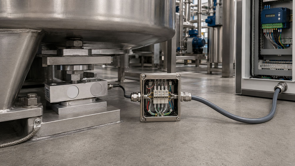
Load cells often provide only a very small analog output signal in the range of a few millivolts. At the same time, the strain gauge measuring bridge must be supplied with a stable excitation voltage through the same cable. If the connection cable is extended, cable resistance, voltage drop, shielding and contact resistance can therefore directly affect measurement accuracy.
The decisive factor is whether the load cell or the weighing electronics operate using 4-wire or 6-wire technology.
With a conventional 4-wire load cell, only the following are available:
- Excitation +,
- Excitation −,
- Signal +,
- Signal −
. The voltage drop in the excitation lines is not measured separately.
A 6-wire load cell additionally has two sense or feedback lines. With these, suitable weighing electronics can measure the actual excitation voltage present at the measuring bridge and compensate for line losses in the excitation conductors.
Particularly important: The connection cable of a calibrated 4-wire load cell should not be shortened or extended without checking the manufacturer’s specifications. If an extension is necessary, a 6-wire extension with sense feedback is often the technically better solution.
Suitable sensors can be found under force, weighing, speed and torque sensors at ICS Schneider. A comprehensive selection can also be found under WIKA load cells and force transducers.
Table of Contents
- Why does cable length affect a load cell?
- Why is the mV/V signal particularly sensitive?
- How does 4-wire technology work?
- How does 6-wire technology work?
- What exactly do the sense lines do?
- How does voltage drop occur in the cable?
- Calculation example for a long cable
- Correctly extending a 4-wire load cell
- Correctly extending a 6-wire load cell
- Connecting a 4-wire load cell to 6-wire electronics
- Connecting a 6-wire load cell to 4-wire electronics
- Why voltage drop on the signal conductors is less critical
- Selecting the correct cable cross-section and length
- Which extension cable should be used?
- Implementing shielding and EMC correctly
- Distance from variable frequency drives and motor cables
- Cable connections and junction boxes
- Why moisture in junction boxes is particularly critical
- Connecting multiple load cells together
- Corner adjustment and junction box
- Is recalibration required after extending the cable?
- Systematically checking the load cell cable
- Practical example: vessel weighing system with a long cable
- Typical fault patterns
- Recommended procedure when extending a cable
- Suitable load cells from ICS Schneider
- Conclusion
- FAQ
Why does cable length affect a load cell?
Most conventional analog load cells operate using a strain gauge Wheatstone bridge.
The bridge requires an electrical excitation voltage, for example:
5 V
or:
10 V
.
Under load, a very small differential output voltage is generated.
The rated output of a load cell is often specified as:
2 mV/V
.
With an excitation voltage of:
10 V
and rated load, this theoretically means:
20 mV
output signal.
The excitation voltage is therefore part of the measurement chain
If the voltage actually present at the strain gauge bridge decreases, its output signal decreases proportionally.
This is exactly why additional resistance in an extended excitation line can cause a measurement error.
Why is the mV/V signal particularly sensitive?
A load cell signal is significantly smaller than typical industrial signals such as:
0 … 10 V
or:
4 … 20 mA
.
Even at rated load, only a few millivolts are often present at the input of the weighing electronics.
Example
A load cell has a rated output of:
2 mV/V
and is excited with:
10 V
.
At 100% load, the signal is:
20 mV
.
At only 1% load, it is approximately:
0.2 mV
or:
200 µV
.
Interference, potential differences, poor contacts and electromagnetic coupling can therefore become relevant much more quickly than with a robust 4–20 mA signal.
How does 4-wire technology work?
A 4-wire load cell uses four active conductors:
- Excitation +,
- Excitation −,
- Signal +,
- Signal −.
A cable shield is also normally present.
The weighing electronics provide the excitation voltage
This voltage is supplied to the strain gauge bridge via the two excitation conductors.
Because every copper conductor has electrical resistance, a voltage drop occurs across the excitation conductors.
The problem
With a pure 4-wire connection, the weighing electronics normally do not directly know the voltage that actually reaches the load cell bridge.
As the cable becomes longer, the conductor resistance increases.
As a result:
- the voltage drop increases,
- the actual bridge excitation voltage decreases,
- the load cell output signal decreases.
The original cable can be part of the calibration
With certain 4-wire load cells, the influence of the factory-installed cable is already taken into account during calibration.
Changing the cable length can therefore also change the electrical sensitivity of the complete measurement chain.
How does 6-wire technology work?
With a 6-wire load cell, two additional conductors are added:
- Sense +,
- Sense −.
The complete connection therefore typically consists of:
- Excitation +,
- Excitation −,
- Sense +,
- Sense −,
- Signal +,
- Signal −,
- plus cable shield.
Sense measures the actual excitation voltage
The two sense lines measure the voltage as close as possible to the strain gauge bridge.
Suitable weighing electronics can therefore determine whether, for example, instead of the intended:
10.00 V
only:
9.80 V
actually reaches the bridge.
The electronics can regulate the voltage
With a true remote-sense function, the electronics increase their output voltage until the intended excitation voltage is again present at the measuring bridge.
The voltage drop across the excitation line is thereby compensated within the permissible regulation limits.
What exactly do the sense lines do?
Sense lines do not supply the load cell with any significant current.
They act as voltage-sensing lines.
This is the decisive difference
The bridge current flows through the excitation lines.
This produces:
Uloss = I · R
.
By contrast, the sense inputs of suitable weighing electronics have a very high input resistance.
Only a very small current therefore flows through the sense lines.
The voltage drop on these lines is correspondingly very small.
The electronics therefore receive feedback
on the actual voltage directly at the remote measurement point.
If the conductor resistance changes, for example due to:
- a longer cable,
- temperature changes in the copper cable,
- different cable temperatures along the installation,
6-wire technology can largely compensate for this influence.
How does voltage drop occur in the cable?
The electrical resistance of a copper conductor depends, in simplified terms, on:
- cable length,
- conductor cross-section,
- material,
- temperature
.
In simplified form:
R = ρ · l / A
where:
R= conductor resistance,ρ= resistivity of the conductor material,l= conductor length,A= conductor cross-section.
For voltage drop:
ΔU = I · R
The outgoing and return conductors must both be considered for excitation
A load cell located 100 m away does not electrically have only 100 m of excitation cable.
The current flows:
100 m out + 100 m back
.
The corresponding loop length must therefore be taken into account when considering voltage drop.
Calculation example for a long cable
A load cell has an example bridge resistance of:
350 Ω
and is excited with:
10 V
.
Bridge current
In simplified form:
I = U / R
therefore:
I ≈ 28.6 mA
100 m connection cable
With an assumed copper conductor cross-section of:
0.5 mm²
the resistance of a 100 m conductor is in the range of several ohms.
Because both the outgoing and return conductors must be considered, the total resistance of the excitation line can already exceed:
7 Ω
.
Voltage drop
At approximately:
28.6 mA
bridge current, this can result in a voltage drop in the region of:
0.2 V
.
Instead of:
10.0 V
only approximately:
9.8 V
is then present at the bridge.
With an uncompensated 4-wire circuit, the mV/V output signal would decrease accordingly.
This example shows why even seemingly small conductor resistances can become relevant with long load cell cables.
Correctly extending a 4-wire load cell
With a 4-wire load cell, it should first be clarified whether the existing connection cable is part of the factory calibration.
Avoid changing the original cable wherever possible
In particular, it should not be:
- shortened,
- replaced,
- substituted with an arbitrary different cable
without manufacturer approval.
If an extension is necessary
one technically advantageous option is to continue from the end of the existing 4-wire cable using a 6-wire extension.
At the transition point:
- Sense + is connected to Excitation + of the load cell,
- Sense − is connected to Excitation − of the load cell.
The six conductors are then routed to weighing electronics capable of 6-wire operation.
What does this compensate for?
The electronics measure the excitation voltage at the end of the original 4-wire load cell cable.
This allows them to compensate for the additional voltage drop on the newly added extension cable.
The voltage drop already present in the unchanged original cable remains part of the original measurement chain.
This is an important reason why this method can be advantageous compared with a simple 4-wire extension.
Correctly extending a 6-wire load cell
With a true 6-wire load cell, extending the cable is generally more favorable.
All six conductors must be extended continuously
This applies to:
- Excitation +,
- Excitation −,
- Sense +,
- Sense −,
- Signal +,
- Signal −.
The shielding must also be continued correctly.
Use a suitable cable
The extension should preferably use a cable designed for strain gauge measurement chains.
Important characteristics include:
- sufficient conductor cross-section,
- symmetrical construction,
- good shielding,
- low and defined capacitance,
- suitable temperature range,
- mechanical suitability for the installation conditions.
The sense lines must be routed all the way to the point whose excitation voltage is to be compensated.
Bridging the sense lines to excitation somewhere in the control cabinet and then running a long 4-wire cable to the load cell does not compensate for the voltage drop on that long section.
Connecting a 4-wire load cell to 6-wire electronics
If the load cell has only four conductors but the weighing electronics have terminals for Sense + and Sense −, these inputs must be wired according to the instructions for the electronics and load cell.
For direct connection without a 6-wire extension
the following are normally bridged:
Sense + ↔ Excitation +
and:
Sense − ↔ Excitation −
.
The exact bridge location depends on the electronics used and the manufacturer’s instructions.
Important
Such a bridge does not turn a 4-wire load cell into a true 6-wire measurement system.
The electronics then receive no separate information about the voltage actually present at the remote strain gauge bridge.
Connecting a 6-wire load cell to 4-wire electronics
The reverse case is also possible.
A load cell has:
- six active conductors,
while the existing weighing electronics have only:
- four terminals.
In this case, the sense lines are normally connected to the corresponding excitation lines
that is:
Sense + to Excitation +
and:
Sense − to Excitation −
.
The load cell then operates electrically essentially as a 4-wire configuration.
Active line-loss compensation using 6-wire technology is then not available.
Why voltage drop on the signal conductors is less critical
The two signal conductors also have electrical resistance.
At first glance, one might therefore expect a significant voltage drop there as well.
The key difference
The input of modern weighing electronics or a strain gauge amplifier normally has a high input resistance.
Only a very small current therefore flows through the signal conductors.
According to:
ΔU = I · R
the resulting voltage drop is correspondingly very small.
The excitation line is more critical
The full bridge current flows there.
This is why 6-wire compensation focuses on the actual excitation voltage present at the bridge.
Selecting the correct cable cross-section and length
A larger conductor cross-section reduces ohmic resistance.
This also reduces the voltage drop.
However, conductor cross-section should not be considered in isolation
For a precise load cell signal, the following are also important:
- conductor symmetry,
- shielding,
- capacitance,
- temperature behavior,
- mechanical robustness.
Very large cross-sections are not automatically the best solution
An arbitrary power cable may have low resistance, but may not be optimized for sensitive strain gauge measurement signals in terms of:
- shielding,
- twisted-pair arrangement,
- capacitance,
- flexibility.
A measurement cable recommended by the sensor or electronics manufacturer should therefore be used.
Which extension cable should be used?
Arbitrary multi-core control cables should not be used for analog load cells.
A suitable load cell or strain gauge cable should
- be shielded,
- have stable conductor geometry,
- be suitable for small measurement signals,
- have sufficiently low conductor resistance,
- match the required temperature range,
- be resistant to the existing environmental conditions.
For moving applications
it must additionally be checked whether the cable is suitable for:
- drag chains,
- repeated bending,
- robotic movements
.
For outdoor applications
the following, among other factors, must be considered:
- UV resistance,
- moisture,
- temperature,
- oil and chemical resistance.
Implementing shielding and EMC correctly
The load cell signal is in the millivolt range and is therefore particularly sensitive to electromagnetic interference.
The cable shield must not simply end at the extension point
The shielding effect should be maintained over the entire measurement cable.
A junction box or connector must therefore provide a technically suitable continuation of the shield.
The grounding strategy depends on the system
Whether the shield is connected:
- at one end,
- at both ends,
- via the sensor housing,
- via a defined functional earth
should be decided according to the manufacturer and EMC requirements of the complete measurement chain.
A blanket rule such as “always connect the shield at one end only” is not sufficient for industrial weighing systems.
Distance from variable frequency drives and motor cables
Parallel cable runs associated with the following are particularly problematic:
- variable frequency drives,
- servo drives,
- motors,
- contactors,
- solenoid valves,
- power electronics.
These can generate high levels of electromagnetic interference.
Load cell cables should therefore be routed separately wherever possible
Long parallel runs in the same cable route should be avoided.
Where power and measurement cables must cross, the crossing should be kept as short and favorable as possible.
The control cabinet is also relevant
The load cell signal should not be routed unnecessarily close to:
- motor feeders,
- inverter outputs,
- mains filters,
- power contactors.
Cable connections and junction boxes
Extending a cable inevitably creates an additional electrical connection point.
This connection should permanently be
- low resistance,
- mechanically stable,
- protected against corrosion,
- shielded,
- protected against moisture.
A suitable junction box is generally better than an improvised connection
In particular, the following should be avoided:
- loose terminal blocks in the machine area,
- unprotected terminal points,
- open twisted wires,
- unsealed connectors.
With very small measurement signals, changing contact resistances and moisture at connection points can already lead to:
- zero drift,
- instability,
- sporadic measurement errors.
Why moisture in junction boxes is particularly critical
A load cell itself may, for example, have a high degree of protection.
However, the complete measurement chain is only as robust as its weakest connection point.
If water enters a junction box
the following may occur:
- reduced insulation resistance,
- creepage currents,
- corrosion,
- changes in contact resistance,
- unstable zero points.
For outdoor scales, silos and vehicle scales, particular attention should therefore be paid to:
- suitable degree of protection,
- cable glands,
- prevention of condensation,
- proper strain relief.
Connecting multiple load cells together
Several load cells are often operated in parallel in vessel, platform and vehicle weighing systems.
Typical setup
Several load cells are connected to a:
junction or summing box
.
From there, a common measurement cable runs to the weighing electronics.
Cable routing becomes even more important
Differences in:
- cable lengths,
- resistances,
- load cell sensitivities
can affect the interaction of the individual measuring points.
With load cells designed for parallel operation, these influences are minimized by design or through matched characteristics.
Corner adjustment and junction box
With a platform using several load cells, the same load should produce as nearly as possible the same weighing result regardless of its position.
A test weight placed in the left corner should therefore not produce a different result from the same weight placed in the right corner.
A junction box can allow corner adjustment
Depending on the system, small differences between the load cell signals can be adjusted accordingly.
If the wiring is later changed, the following may also change:
- conductor resistances,
- adjustment conditions,
- EMC characteristics.
After major changes to a multi-load-cell weighing system, not only the zero point but also the load distribution or corner adjustment should therefore be checked.
Is recalibration required after extending the cable?
After any change to load cell wiring, the complete measurement chain should generally be checked.
With a 4-wire load cell
a change in cable length can directly affect the sensitivity.
Readjustment or recalibration is therefore particularly important.
With a correctly implemented 6-wire extension
the additional voltage drop is largely compensated by the sense lines.
However, this does not mean that the system should be returned to service without verification.
After the change, at minimum check
- zero point,
- span,
- repeatability,
- corner loading where applicable,
- signal stability.
For weighing systems subject to legal metrology requirements, the applicable statutory or metrological requirements must additionally be observed.
Systematically checking the load cell cable
If measurement problems occur after extending the cable, the load cell itself should not immediately be replaced.
Check the excitation voltage
The following should be checked:
- voltage at the weighing electronics,
- voltage at the load cell or sense point,
- difference between the two values.
Check the sense lines
Check:
- Sense + correctly assigned,
- Sense − correctly assigned,
- no open circuit,
- no swapped conductors.
Check the measurement signal
Under load, the differential signal should change:
- smoothly,
- reproducibly,
- without jumps.
Check the shielding
Interrupted or incorrectly implemented shielding can lead to strongly fluctuating measured values, particularly in the vicinity of variable frequency drives.
Mechanically inspect connection points
Faults are particularly suspicious if they change when:
- the cable is moved,
- the junction box is touched,
- moisture or temperature changes.
Practical example: vessel weighing system with a long cable
A production vessel is supported by four load cells.
The load cells are connected together in a junction box.
The existing weighing electronics are located:
10 m
away.
During a plant modification, the control cabinet is relocated.
The new cable length between the junction box and weighing electronics is:
80 m
.
Variant 1: simple 4-wire extension
The additional cable increases the resistance of the excitation lines.
This reduces the voltage at the load cells.
The overall system sensitivity can change accordingly.
Variant 2: 6-wire extension with sense
From the junction box to the weighing electronics, the following additional conductors are routed:
- Sense +,
- Sense −
.
These measure the excitation voltage at the junction box.
The weighing electronics can therefore compensate for the voltage drop along the 80 m extension cable.
After the modification
the following are checked:
- zero point,
- reference load,
- repeatability,
- corners or individual support points.
This verifies not only the electrical function of the sense compensation, but the complete weighing system after the modification.
Typical fault patterns
| Observation | Possible cause | Recommended check |
|---|---|---|
| Scale indicates too little after cable extension | Additional voltage drop in 4-wire excitation line | Compare excitation voltage at electronics and load cell |
| Error increases with cable length | Conductor resistance not compensated | Check 6-wire sense function |
| Measured value changes with ambient temperature | Temperature-dependent cable resistance | Check sense function and cable temperature |
| 4-wire load cell has a different sensitivity after shortening the cable | Original cable was part of the calibrated measurement chain | Check manufacturer data and recalibrate |
| 6-wire load cell behaves like a 4-wire load cell | Sense lines bridged only at the electronics or not used | Check complete sense connection |
| Weighing electronics report a sense error | Sense line interrupted or reversed | Check continuity and conductor assignment |
| Measured value jumps when motor is operating | EMC interference | Check cable routing, shielding and equipotential bonding |
| Measured value drifts after rain | Moisture in junction box or connector | Check insulation condition and sealing |
| Zero point changes when cable is moved | Contact problem or cable break | Mechanically inspect cable and terminals |
| Measured value is permanently wrong by a constant factor | Span or sensitivity not adjusted after wiring change | Perform calibration using a reference load |
| Only one corner of the platform shows incorrect values | Problem with one load cell or changed corner adjustment | Check individual loads and junction box |
| Signal is unstable although the load is constant | Shield interruption, potential difference or EMC interference | Check shielding and cable routing |
| Load cell works directly at the amplifier but not through the extension | Fault in extension cable or junction box | Check each conductor for continuity and insulation |
| Measured value shifts after replacing cable with a different cross-section | Changed resistance of excitation line | Check sense function or recalibration |
Recommended procedure when extending a cable
- Identify the load cell type: Determine manufacturer, type and datasheet.
- Check the output signal: For example mV/V.
- Determine connection type: Distinguish between 4- and 6-wire technology.
- Document the original cable length: Record it before making any changes.
- Check calibration information: Determine whether the original cable is part of the calibration.
- Determine the required extension: Define the actual cable length needed.
- Check the weighing electronics: Determine whether true 6-wire sense inputs are available.
- Select suitable measurement cable: Use shielded strain gauge or load cell cable.
- Check conductor cross-section: Take voltage drop into account.
- For a 4-wire load cell, preferably consider a 6-wire extension: Connect sense at the end of the original cable.
- For a 6-wire load cell, extend all six conductors: Route sense completely to the sensor.
- Continue shielding throughout: Observe the manufacturer’s EMC concept.
- Define the cable route: Maintain distance from power and motor cables.
- Select a suitable junction box: Consider degree of protection and environmental conditions.
- Clearly assign terminals: Do not confuse excitation, sense and signal.
- Do not assume conductor colors: Use the connection diagram of the specific sensor.
- Check excitation voltage: Compare values at the electronics and sense point.
- Check the zero signal: Test the scale unloaded.
- Apply a reference load: Check span.
- Check repeatability: Apply and remove the reference load several times.
- For multi-load-cell systems, check corners: Compare individual load positions.
- Check EMC behavior: Test the system with motors and variable frequency drives operating.
- Readjust or recalibrate the measurement chain if necessary: Especially after changes to 4-wire systems.
- Document the modification: Record cable type, length, connection type and calibration data.
Suitable load cells from ICS Schneider
WIKA Type F3831 – shear beam for industrial weighing applications
The WIKA Type F3831 is a shear beam for industrial weighing and force measurement applications.
Key features include:
- measuring ranges from 0 … 500 kg to 0 … 10,000 kg,
- mV/V output signal,
- versions made of steel or stainless steel,
- high long-term stability,
- high resistance to side loads.
Typical applications include:
- floor scales,
- batching scales,
- platform scales,
- vessel weighing,
- process industry.
WIKA Type F4801 – platform load cell
For smaller platform and industrial scales, the WIKA Type F4801 is available, among others.
It offers:
- measuring ranges from 0 … 3 kg to 0 … 250 kg,
- aluminum measuring body,
- high accuracy,
- low sensitivity to side and corner loads,
- easy integration into platform scales.
WIKA Type F1270 – high-capacity load cell for vessels and silos
For significantly larger loads, the WIKA Type F1270 is available.
The load cell is designed for compression forces and measuring ranges from:
7.5 t … 300 t
.
Typical applications include:
- vessel weighing,
- silo weighing,
- batching systems,
- test and production systems,
- truck scales.
Further sensors can be found under WIKA load cells and force transducers at ICS Schneider.
Conclusion
A load cell cable cannot be extended like an arbitrary sensor cable without considering the electrical measurement chain.
With 4-wire load cells, conductor resistance affects the excitation voltage
Additional cable resistance can reduce the voltage present at the strain gauge bridge and therefore change the sensitivity.
The original cable may be part of the calibration
For this reason, 4-wire cables should not be shortened or modified without manufacturer approval.
6-wire technology compensates for line losses
Sense + and Sense − measure the actual bridge excitation voltage and allow suitable electronics to regulate the supply voltage accordingly.
With a 4-wire load cell, a 6-wire extension can be useful
In this case, sense is connected to the corresponding excitation conductor at the end of the original load cell cable. This allows at least the additional voltage drop along the extension section to be compensated.
A suitable measurement cable is essential
In addition to conductor resistance, shielding, symmetry, capacitance and temperature behavior must be considered.
Shielding must not be lost when extending the cable
The complete measurement chain requires a coordinated EMC concept.
Variable frequency drives and motor cables are typical sources of interference
Load cell cables should therefore be routed separately from power cables wherever possible.
Connection points must be permanently protected
Moisture and changing contact resistance can cause significant measurement errors with millivolt signals.
The complete scale must be checked after any modification
Zero point, span, repeatability and, where applicable, corner loading should be checked using suitable reference loads.
For practical applications
Determine load cell type and connection method → check datasheet → document original cable length → distinguish between 4- and 6-wire technology → check the sense capability of the electronics → select suitable shielded measurement cable → for 4-wire load cells, keep the original cable unchanged wherever possible and extend using 6-wire technology if appropriate → for 6-wire load cells, continue all sense lines completely → ensure continuous shielding and EMC-compliant cable routing → protect connection points against moisture → check excitation voltage and sense values → verify zero point, span and repeatability → readjust or recalibrate the measurement chain after the modification if necessary.
FAQ: Extending Load Cell Cables and Sense Lines
Can a load cell cable be extended?
Yes, an extension is generally possible. However, the correct procedure depends on whether the load cell and weighing electronics use 4- or 6-wire technology.
What is a 4-wire load cell?
It has two active conductors for bridge excitation and two for the measurement signal: Excitation +/− and Signal +/−.
What is a 6-wire load cell?
In addition to excitation and measurement signal, it has two sense lines for measuring the actual excitation voltage at the measuring bridge.
What does sense mean on a load cell?
Sense refers to feedback lines through which suitable weighing electronics can measure the actual supply voltage at the remote measurement point.
Why are sense lines needed?
They allow compensation for voltage drop in long excitation lines and therefore reduce the influence of cable length and temperature-dependent cable resistance.
Why does voltage drop occur at all?
Every copper conductor has electrical resistance. When bridge current flows through this resistance, a voltage drop occurs according to ΔU = I × R.
Why does the excitation voltage affect the measurement result?
The output signal of a conventional strain gauge load cell is proportional to the actual excitation voltage present at the measuring bridge.
What does 2 mV/V mean?
A load cell with a rated output of 2 mV/V produces 2 mV output voltage per volt of bridge excitation at rated load. With 10 V excitation, this would theoretically be 20 mV.
Can I simply extend a 4-wire load cell cable?
A simple 4-wire extension can increase the excitation-line resistance and therefore influence the sensitivity. The manufacturer’s specifications must therefore be checked.
May a 4-wire load cell cable be shortened?
For load cells whose original cable is included in the factory calibration, it should not be shortened because this can change the sensitivity.
What is the best way to extend a 4-wire load cell?
If the weighing electronics support sense, a 6-wire extension can be used from the end of the original cable. The sense lines are connected there to the corresponding excitation conductors.
What is the benefit of using a 6-wire extension with a 4-wire load cell?
It allows compensation for the additional voltage drop on the extension cable. The influence of the unchanged original cable remains.
Can a true 6-wire load cell be extended indefinitely?
The permissible cable length and the specifications of the weighing electronics must still be observed. However, 6-wire technology is technically much better suited to long cable runs.
Do Sense + and Sense − also have to be extended?
Yes. For true remote-sense compensation, the sense lines must be routed all the way to the intended measurement point.
What happens if a sense line is interrupted?
Depending on the weighing electronics, error messages, incorrect excitation voltages or implausible measured values may occur.
May Sense + be connected to Sense −?
No. Sense + belongs to the positive excitation potential and Sense − to the negative excitation potential.
How is a 6-wire load cell connected to 4-wire electronics?
Normally, Sense + is connected to Excitation + and Sense − to Excitation −. The manufacturer’s instructions are decisive.
Do I still have sense compensation in that case?
No. Without separate sense inputs in the weighing electronics, active line-loss compensation is not available.
Are load cell conductor colors standardized?
No. The conductor assignment should always be determined from the connection diagram of the specific load cell type.
Can I use normal control cable for the extension?
For precise mV/V measurements, a suitable shielded strain gauge or load cell measurement cable should be used.
Why is shielding so important?
Load cells provide only very small electrical signals. Electromagnetic interference can therefore couple into the measurement cable comparatively easily.
Should the cable shield be grounded at one end or both ends?
This depends on the sensor, weighing electronics and the EMC or equipotential bonding concept. The manufacturer’s instructions should be followed.
Can the load cell cable be routed next to a motor cable?
Long parallel routing next to motor cables or variable frequency drive cables should be avoided wherever possible because strong electromagnetic interference can occur there.
Why can moisture in a junction box cause measurement errors?
Moisture can reduce insulation resistance, cause corrosion and create additional creepage or leakage currents.
Can I solder a cable extension?
A permanent connection must be electrically stable, mechanically protected and sealed against moisture. In industrial weighing systems, a suitable junction or summing box is often the more robust solution.
Does the system have to be recalibrated after extending the cable?
The complete measurement chain should be checked after every relevant wiring change. With 4-wire systems, readjustment or recalibration is particularly important.
Does a 6-wire extension mean that calibration is no longer necessary?
Sense technology compensates for line losses but does not replace functional verification of the complete scale. Zero point, span and repeatability should still be checked.
What should be checked after extending the cable?
At minimum, zero point, reference load, repeatability and signal stability should be checked. For multi-load-cell systems, the corner or support-point adjustment should also be verified.
Why does a 4-wire system change with cable temperature?
The electrical resistance of copper increases with temperature. This can increase the voltage drop in the excitation lines.
Can a 6-wire circuit compensate for cable temperature changes?
Yes. Correctly implemented sense regulation can largely compensate for changes in voltage drop caused by temperature-dependent conductor resistance.
How can I identify a broken cable?
Typical indications include jumps, dropouts or changes in measured value when the cable is moved. Continuity and insulation testing of the individual conductors can help locate the fault.
Why is the signal constantly unstable after the extension?
Possible causes include poor shielding, unfavorable cable routing, equipotential bonding problems, poor contacts or moisture.
Which WIKA load cell is suitable for vessel and platform scales?
Depending on the load and design, options include the WIKA F3831 shear beam or various platform and high-capacity load cells.
Where can I find further load cells and force transducers?
Further solutions can be found under force, weighing, speed and torque sensors at ICS Schneider.