


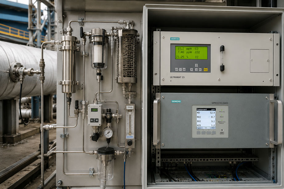
A process gas analyzer suddenly indicates concentrations that are too low, responds significantly more slowly than before or provides fluctuating measured values.
The analyzer is checked and supplied with test gas.
The result:
Analyzer operates correctly.
So where is the problem?
Very often, it is not in the actual measuring instrument but upstream of it.
In extractive gas analysis, the measuring point consists of much more than just the analyzer:
Process → sampling probe → sample line → filter → cooler / conditioning → condensate drain → pressure regulation → pump → flow control → analyzer
Every element in this chain can influence the composition or the time response of the gas sample.
Typical problems include:
- condensation in an unheated line,
- clogged particle filters,
- blocked condensate drains,
- sample gas flow that is too low or fluctuates significantly,
- incorrectly adjusted inlet pressure,
- leaks on the suction side of a pump,
- excessive dead volumes,
- unsuitable hose or tubing materials,
- long transport times,
- different gas paths for process gas and calibration gas.
Condensate is particularly critical.
If the sample gas falls below its dew point anywhere between the process and the analyzer, liquid can condense. This not only changes the physical state of the sample – depending on the measured component, it can also change its composition.
Water-soluble or condensable components can partially be removed together with the condensate. At the same time, droplets can damage filters, pumps, valves and measuring cells or distort the measurement.
Sample conditioning is therefore not merely an accessory.
In extractive gas analysis, sample conditioning is part of the measurement system.
Siemens instruments for process analytics and gas analyzers can be found at ICS Schneider under Siemens Process Analytics / Gas Analyzers. Further Siemens solutions for industrial process measurement can be found under Siemens Process Instrumentation.
Table of Contents
- Why sample conditioning is part of the measurement
- Distinguishing between extractive and in-situ gas analysis
- Consider the complete sample gas chain
- Understanding dew point and condensation
- When a heated sample gas line is required
- Using a sample gas cooler correctly
- Reliably draining condensate
- Correctly select and monitor particle filters
- Stabilizing sample gas pressure
- Correctly assess the sample gas pump
- Correctly adjust sample gas flow
- Using a bypass to reduce response time
- Correctly distinguish dead time and T90
- Estimate transport time from line volume and flow
- Consider material compatibility of the gas path
- Special considerations for hydrogen
- Introduce calibration gas appropriately
- Organize maintenance of the sample conditioning system
- Typical fault patterns
- Systematic troubleshooting
- Practical example: analyzer suddenly measures correctly after filter replacement
- Suitable ICS products
- Conclusion
- FAQ
Why sample conditioning is part of the measurement
A gas analyzer can only analyze the gas that actually reaches its measuring cell.
This may sound obvious, but it is often underestimated during troubleshooting.
Assume that the process contains:
500 ppm of a measured component
However, due to condensation, adsorption or leakage, only:
430 ppm
reaches the analyzer.
The analyzer itself can then operate perfectly correctly and still indicate a value that is incorrect for the actual process.
The actual measurement system is therefore not:
gas analyzer
but:
sampling + transport + conditioning + analyzer + evaluation
Three functions of sample conditioning
A suitable sample conditioning system should essentially:
- transport the gas to the analyzer,
- protect the analyzer from unsuitable process conditions,
- preserve the gas composition relevant to the measurement as representatively as possible.
These objectives can influence one another.
A sample gas cooler, for example, protects an analyzer from excessive moisture.
At the same time, it must be checked whether the component of interest:
- condenses,
- dissolves in the condensate,
- adsorbs onto surfaces
during cooling and is therefore partially lost.
Distinguishing between extractive and in-situ gas analysis
Two common concepts can generally be distinguished.
Extractive gas analysis
With extractive measurement, a partial gas flow is taken from the process and transported to the analyzer.
Typical configuration:
Process → sampling probe → sample gas line → sample conditioning → analyzer
Advantages include:
- the analyzer can be installed in a protected control cabinet,
- several measuring principles can be combined,
- the gas can be specifically filtered, cooled or pressure-regulated,
- maintenance can often be performed outside the actual process.
The disadvantage:
An additional measurement chain is created between the process and the analyzer, which can alter the gas and increase the response time.
In-situ gas analysis
With an in-situ measurement, the analysis is performed directly at or inside the process.
With optical systems, for example, the measurement is performed directly through the gas stream.
This eliminates many components of conventional extractive sample conditioning.
In particular, there are no long sample gas lines with:
- transport time,
- condensate formation,
- filter loading,
- sample gas pumps.
In-situ is nevertheless not automatically better
Which solution is suitable depends, among other things, on:
- measured component,
- measuring range,
- process temperature,
- pressure,
- dust loading,
- measuring location,
- required response time,
- accessibility,
- desired measuring principle.
The selection must therefore be application-specific.
Consider the complete sample gas chain
During troubleshooting, every component from the process to the analyzer should be considered individually.
| Component | Function | Typical source of error |
|---|---|---|
| Sampling probe | Extract a representative gas sample | Blockage, incorrect position, condensation |
| Prefilter | Remove coarse particles | Clogging, pressure loss |
| Heated line | Maintain temperature above critical condensation limits | Heating failure, cold spots |
| Sample gas cooler | Reduce moisture in a controlled manner | Insufficient cooling, condensate accumulation |
| Condensate pump / drain | Remove separated condensate | Blockage, backflow |
| Fine filter | Protect analyzer from particles | Filter loading, adsorption |
| Pressure regulator | Stabilize gas pressure | Incorrect outlet pressure, unstable regulation |
| Sample gas pump | Ensure gas transport | Wear, leakage, insufficient delivery rate |
| Flow control | Set a defined sample gas flow | Flow too low or fluctuating |
| Analyzer | Determine concentration | Contamination, drift, calibration error |
The order of these components is not identical in every system.
It depends on:
- process conditions,
- measuring principle,
- analyzer,
- measured components,
- safety requirements.
Understanding dew point and condensation
Moist process gas contains water vapor.
The amount of water vapor that can remain in the gaseous state depends strongly on temperature.
If the gas temperature falls below the dew point, water begins to condense.
In simplified form:
Tgas path < Tdew point → risk of condensation
Typical case
Sample gas leaves a hot process at:
150 °C
and then passes through an unheated line into a control cabinet at:
20 °C
If the gas dew point is higher than the temperature in individual sections of the line, water will condense there.
Condensate does not always remain in one place
Liquid can:
- remain in low points of the line,
- flow toward the filter,
- be transported further in batches,
- reach a pump,
- reach the measuring cell.
This often causes intermittent faults.
For example, the system may operate correctly for hours and then suddenly produce unstable values.
Condensation can change the gas composition
This is particularly important from a measurement perspective.
Certain measured components may:
- be water-soluble,
- react with condensate,
- be condensable themselves.
The remaining gas downstream of the condensation point then no longer corresponds exactly to the original process sample.
Condensate is therefore not only a mechanical problem but can directly cause a measurement error.
When a heated sample gas line is required
A heated sample gas line is used when condensation must be prevented during transport.
The principle is:
keep the gas temperature in the line safely above the relevant condensation temperature
Typical applications
- moist flue and process gases,
- hot exhaust gases,
- measurements upstream of defined gas conditioning,
- measured components that must not condense prematurely,
- dust and moisture exposure in emission measurements.
The entire line must be considered
It is not sufficient if 95% of the line is heated.
A single cold spot can be enough for condensate to form.
Critical areas include:
- transitions at the sampling probe,
- fittings,
- unheated valves,
- control cabinet penetrations,
- the transition to the sample gas cooler.
Do not increase the temperature arbitrarily
A heated line should not simply be operated as hot as possible.
The following must be considered:
- maximum permissible line temperature,
- materials,
- filters,
- seals,
- thermal stability of the measured components.
The setpoint temperature must be suitable for the respective analysis system.
Using a sample gas cooler correctly
A sample gas cooler takes a different approach from a heated line.
Here, the moisture is not kept in the gaseous state but is deliberately condensed and then removed from the gas stream.
The principle is:
moist gas → controlled cooling → condensation → condensate drainage → defined dried sample gas
Why controlled cooling is better than random condensation
With uncontrolled condensation, it is unknown:
- where the condensate forms,
- how much condensate forms,
- how long it remains in the line,
- which measured components are absorbed by it.
A suitable sample gas cooler, on the other hand, creates defined conditions.
The cooler must suit the measuring method
Conventional cooling and drying is not appropriate for every gas analysis application.
If the component to be measured is highly water-soluble or itself condensable, conditioning can change the concentration.
In such cases, the following may be required, for example:
- heated wet-gas measurement,
- a different measuring principle,
- special permeation drying,
- a different process configuration.
Sample conditioning must therefore be designed according to the measured component – not merely according to what is convenient for the analyzer.
Reliably draining condensate
A sample gas cooler only works reliably if the separated condensate is also removed.
Depending on the system, this can be achieved using:
- peristaltic pumps,
- condensate collection vessels,
- automatic condensate drains.
Blocked condensate drain
If the drain is blocked, liquid can accumulate in the cooler.
Possible consequences include:
- increasing flow resistance,
- fluctuating flow,
- entrainment of liquid,
- moisture breakthrough to the analyzer.
Do not simply return condensate to the sample
The separated condensate must remain reliably separated from the sample gas.
An improperly routed drain hose can, for example:
- cause back pressure,
- create a siphon effect,
- influence the pressure conditions in the cooler.
Correctly select and monitor particle filters
Particle filters protect:
- measuring cells,
- valves,
- pumps,
- flow controllers
from dust and solids.
The filter is a wear component within the measurement chain.
What happens as filter loading increases?
Flow resistance increases.
As a result:
- sample gas flow may decrease,
- vacuum on the suction side may increase,
- transport time may increase,
- a pump may operate outside its favorable operating point.
Do not assess filter condition only visually
A filter may still appear acceptable from the outside while nevertheless producing a high pressure drop.
Depending on the system, useful measures therefore include:
- fixed maintenance intervals,
- differential-pressure monitoring,
- flow monitoring,
- comparison with reference values after filter replacement.
Consider the filter material
The filter material must not only retain the required particle size.
It must also not significantly:
- adsorb,
- absorb,
- chemically alter
the components to be analyzed.
This becomes particularly important at very low concentrations.
Stabilizing sample gas pressure
Extractive gas analyzers operate within defined pressure ranges.
A strongly fluctuating process pressure should therefore not be transferred directly to the analyzer without evaluation.
Why pressure fluctuations can be problematic
Depending on the measuring principle and instrument design, they can influence:
- gas density,
- mass flow,
- volumetric flow,
- measuring cell conditions,
- pump operation.
With certain measuring principles, gas pressure can also have a direct influence on the measurement signal.
Position the pressure regulator correctly
Whether pressure regulation takes place upstream or downstream of certain components depends on the complete gas path.
The following must be considered, for example:
- process pressure,
- pump arrangement,
- permissible analyzer inlet pressure,
- condensation behavior,
- flow control.
The outlet is also relevant
A gas path that appears to be pressureless can be subjected to unwanted back pressure at the outlet.
Possible causes include:
- a long exhaust line,
- a small internal diameter,
- a common exhaust manifold,
- a clogged outlet filter,
- condensate in the exhaust line.
This can change the pressure conditions inside the analyzer.
Correctly assess the sample gas pump
In many extractive systems, a pump continuously transports sample gas from the process to the analyzer.
A pump does more than create flow
At the same time, it creates different pressure conditions on the:
- suction side,
- discharge side.
This is important for troubleshooting.
Leak on the suction side
In a line operating under vacuum, a small leak does not necessarily cause process gas to escape to the outside.
Instead, ambient air can be drawn into the measuring system.
This dilutes the sample.
Typical result:
measured value too low
even though no external gas leak is visible.
Pump wear
Diaphragms, valves or other pump components can age.
The flow then gradually decreases.
The analyzer continues to function, but:
- transport time increases,
- response time becomes longer,
- the flow may fall below the recommended range.
Correctly adjust sample gas flow
Sample gas flow is a key parameter in an extractive measurement.
Insufficient flow often means:
- long transport time,
- slow response,
- greater influence of small leaks,
- poorer purging of dead volumes.
However, excessive flow is not automatically better either.
It can:
- cause excessive pressure losses,
- place greater load on filters,
- exceed the permissible analyzer flow,
- unnecessarily load pumps and coolers.
Set the flow according to the manufacturer specification
The correct question is therefore not:
“What is the maximum flow we can get through the line?”
but:
“What sample gas flow is specified for the analyzer and sample conditioning system?”
Monitor the flow
Flow monitoring can provide early detection of:
- a clogged filter,
- a weak pump,
- a crushed line,
- a blocked cooler,
- a closed shut-off valve.
It is therefore a particularly useful diagnostic parameter.
Using a bypass to reduce response time
For long sample lines, a bypass system can be useful.
A larger gas flow is transported rapidly from the sampling point to a location close to the analyzer.
Only a small, defined partial flow is then supplied to the analyzer.
In simplified form:
Process → high bypass flow → branch → defined analyzer flow
Advantage
The large volume of the long main line is exchanged more quickly.
This can significantly reduce transport time without operating the analyzer itself at an impermissibly high flow rate.
A bypass should not be used without a reason
Additional lines and valves also mean:
- more sealing points,
- more components,
- higher gas consumption,
- additional maintenance effort.
It should therefore be used where the required response time actually makes it necessary.
Correctly distinguish dead time and T90
In gas analysis, different time components are often grouped together under the term “response time.”
Technically, they should be considered separately.
Transport time
The time required for a changed gas sample to travel from the process to the analyzer.
Purging time
The time required until:
- filters,
- coolers,
- lines,
- dead volumes
are sufficiently filled with the new gas.
Analyzer response time
The analyzer itself has its own dynamic response.
A T90 time, for example, is often specified.
In simplified terms, it describes the time required after a change in concentration for approximately 90% of the final signal to be reached.
Overall system response
The actual system response therefore consists, in simplified form, of:
transport + sample conditioning + purging + analyzer dynamics + signal damping
A fast analyzer T90 therefore does not guarantee a fast overall measurement.
Estimate transport time from line volume and flow
The approximate transport time can be estimated from the line volume and the actual gas volumetric flow.
For a round line:
V = π · d² / 4 · L
where:
- V = internal line volume,
- d = internal diameter,
- L = line length.
An idealized transport time is:
t ≈ V / Q
where:
- t = transport time,
- V = gas volume,
- Q = actual volumetric flow under the respective line conditions.
Example
Sample line:
L = 10 m
Internal diameter:
d = 4 mm
This gives approximately:
V ≈ 0.126 l
At a flow rate of:
Q = 1 l/min
the idealized pure transport time is:
t ≈ 0.126 min ≈ 7.6 s
However, this does not mean that the complete system has already reached 90% of the new final value after 7.6 seconds.
Additional effects include:
- filter volume,
- cooler volume,
- valves,
- measuring cell,
- mixing,
- adsorption and desorption effects,
- analyzer dynamics.
The formula therefore provides an order-of-magnitude estimate and is not a complete dynamic model.
Consider material compatibility of the gas path
Not every hose, tubing or sealing material is equally suitable for every gas component.
Relevant factors include:
- chemical resistance,
- adsorption,
- absorption,
- permeation,
- temperature resistance,
- pressure resistance.
Particularly critical for trace measurements
At concentrations in the percent range, a small surface effect may barely be noticeable.
At:
ppm or ppb measurements
the same effects can become significant.
Long plastic hoses
Depending on the gas, plastic hoses can:
- allow gases to permeate,
- absorb components,
- produce slow memory effects.
The material selection should therefore always match the specific measured component and concentration.
Special considerations for hydrogen
In process analytics, hydrogen is frequently determined using its thermal conductivity, which differs significantly from that of many other gases.
Typical applications include:
- hydrogen production,
- electrolysis,
- protective gases,
- chemical processes,
- hydrogen/carrier-gas mixtures.
Gas composition in thermal-conductivity measurement
With a thermal-conductivity analyzer, the measurement signal depends on the thermal properties of the entire gas mixture.
Changes in the composition of accompanying gases can therefore be relevant.
The application must accordingly be:
- binary,
- quasi-binary
or manageable using suitable cross-gas correction.
Condensate also remains relevant in H₂ applications
The fact that the target component hydrogen itself remains gaseous under typical process conditions does not mean that no sample conditioning is required.
Accompanying gases may contain, for example:
- water vapor,
- electrolyte residues or aerosols,
- particles,
- other process components.
These can affect filters, lines or the measuring cell.
Leak tightness is particularly important
For H₂, the sample line must also be consistently designed for leak tightness.
A leak can:
- distort the measurement result,
- release process gas,
- draw in ambient air under vacuum.
Introduce calibration gas appropriately
During calibration, it should first be clear what exactly is intended to be tested.
Testing only the analyzer
If test gas is introduced directly at the analyzer inlet, the following are primarily tested:
- measuring cell,
- electronics,
- signal processing.
The upstream sample conditioning system is bypassed.
Testing the complete measurement chain
If the test gas is introduced further upstream in the gas path, parts of the sample conditioning system can also be evaluated.
Depending on the injection point, this can include:
- line,
- filter,
- valves,
- cooler,
- pump,
- flow control.
The two tests provide different information
A typical diagnostic pattern is:
Test gas directly at analyzer: correct
Test gas through complete gas path: value too low
The cause is then very likely located upstream of the actual analyzer.
Zero gas and test gas
Depending on the measuring principle, the following may be used, for example:
- zero gas,
- span or test gas,
- ambient air for automatic adjustment procedures designed for this purpose.
Gas type, concentration, flow and pressure must be suitable for the respective analyzer.
Organize maintenance of the sample conditioning system
In many analysis systems, sample conditioning requires more regular maintenance than the analyzer itself.
A suitable maintenance plan should therefore not list only the analyzer.
Typical maintenance points
- inspect the sampling probe,
- clean or replace the prefilter,
- check the heated line for proper operation,
- check cooler temperature or outlet dew point,
- check the condensate drain,
- check peristaltic pump tubing,
- replace the fine filter,
- check the sample gas pump,
- check the flow,
- check the system for leakage,
- perform calibration or functional testing.
Define maintenance intervals according to actual loading
A filter used in a clean protective-gas process has a completely different service life from a filter used in a dust-laden flue-gas process.
A useful approach is therefore to combine:
- manufacturer specifications,
- experience,
- operating hours,
- flow development,
- differential pressure,
- fault history.
Typical fault patterns with extractive gas analyzers
| Observation | Possible cause | Recommended check |
|---|---|---|
| Measured value responds increasingly slowly | Filter clogged or flow too low | Check sample gas flow and filter condition |
| Measured value suddenly significantly too low | Leak on suction side or loss of measured component | Perform leak test and inspect gas path |
| Measured value fluctuates periodically | Condensate is transported further intermittently | Check line routing, cooler and condensate drain |
| Filter is continuously wet | Condensation upstream of the intended cooler | Check sample line temperature |
| Analyzer correct with test gas, process measurement incorrect | Fault in sampling or sample conditioning | Introduce test gas further upstream in the gas path |
| Flow too low after several weeks | Filter loading or pump wear | Check filter and pump separately |
| Flow fluctuates despite constant pump operation | Condensate, pressure fluctuation or blocked line | Check pressure and condensate drainage |
| Measured value slowly returns after material or gas change | Adsorption / desorption in gas path | Evaluate materials and purging time |
| Response time significantly longer than analyzer T90 | Transport volume and dead volume dominate | Check line volume, flow and bypass |
| Cooler operates but moisture still reaches analyzer | Condensate drain malfunction or insufficient cooling capacity | Check cooler and drain |
| Measured value changes with process pressure | Pressure dependence or unstable sample gas conditions | Check pressure regulation and analyzer conditions |
| Measured value decreases after connection of a long exhaust line | Back pressure at analyzer outlet | Check outlet pressure and line |
| Calibration directly at instrument passed, system test failed | Sample conditioning alters the sample | Check gas path section by section |
Systematic troubleshooting of incorrect gas analysis
A structured diagnostic procedure prevents the analyzer from being adjusted or recalibrated prematurely.
- Check process plausibility: Can an actual concentration change be ruled out?
- Check analyzer status: Review error messages, maintenance status and diagnostic data.
- Check sample gas flow: Is the current value within the specified range?
- Check gas pressure: Verify inlet and, where applicable, outlet conditions.
- Supply test gas directly to the analyzer: Evaluate the basic function of the instrument.
- Check filters: Inspect contamination and pressure loss.
- Check gas path for condensate: Pay particular attention to low points, filter housings and pumps.
- Check heating: Verify setpoint and actual temperatures of the probe and line.
- Check sample gas cooler: Verify cooling capacity and temperature.
- Check condensate drainage: Ensure unrestricted drainage or correct pump operation.
- Check pump: Verify delivery capacity and condition.
- Perform leak testing: Pay particular attention to the suction side.
- Check bypass: Verify actual flow and branch flow to the analyzer.
- Determine dead time: Generate a concentration step and measure the time until the response occurs.
- Review materials: Are hoses, filters and seals suitable for the measured component?
- Route calibration gas through a larger portion of the measurement chain: Narrow down the fault location.
- Document results: Record flow, pressure, temperatures and response times.
Practical example: analyzer suddenly measures correctly after filter replacement
An extractive gas analyzer continuously monitors a process component.
The usual measured value is approximately:
800 ppm
Over several weeks, the indicated value gradually decreases to:
650 ppm
At the same time, the system responds significantly more slowly to process changes.
Step 1: Test the analyzer with test gas
A certified test gas is introduced immediately upstream of the analyzer.
The target value is reached correctly.
The analyzer itself therefore initially appears to be operating correctly.
Step 2: Check the flow
The normally adjusted sample gas flow is:
1.0 l/min
However, only:
0.45 l/min
is now measured.
Step 3: Check the filter
The fine filter is heavily loaded.
Due to the increasing pressure loss, the sample gas pump can no longer maintain the original flow.
Step 4: Replace the filter
After proper filter replacement, the sample gas flow increases again to:
1.0 l/min
Step 5: Observe the response
The concentration returns toward the expected process value.
Changes in concentration are also indicated significantly faster.
Why could the value become lower in the first place?
Low flow alone does not automatically produce a proportionally lower concentration value with every measuring principle.
However, it can amplify several other effects:
- longer transport time,
- greater influence of small leaks,
- longer contact time with surfaces,
- insufficient purging of dead volumes.
In this example, a small leak is therefore additionally found on the suction side.
At the lower gas flow, the ambient air drawn in had a significantly greater dilution effect.
Result
The analyzer was not the cause.
The combination of:
clogged filter + reduced flow + small suction-side leak
resulted in:
- slower response,
- diluted sample,
- measured value that was too low.
The correct diagnostic approach was therefore to check the complete sample gas chain rather than readjust the analyzer based on the process value.
Suitable ICS products for continuous process gas analysis
Siemens ULTRAMAT 23 – multi-component gas analyzer for extractive measurements
The Siemens ULTRAMAT 23 available from ICS is a multi-component gas analyzer for continuous extractive measurements.
Depending on the configuration, different measuring principles or sensors can be combined.
Measurable components include, for example:
- CO,
- CO₂,
- NO,
- SO₂,
- CH₄,
- O₂,
- H₂S.
Depending on the configuration, up to four gas components can be measured in one instrument.
Particularly relevant to the subject of this article:
The measuring cells are designed so that they can be cleaned in the event of contamination.
This is useful when faults in the sample conditioning system have caused contamination inside the analyzer.
However, this does not replace correctly designed gas conditioning.
A cleanable measuring cell should not be considered a substitute for filtration, condensate management and correct flow.
Further information can be found under Siemens ULTRAMAT 23 at ICS Schneider.
SIPROCESS GA700 – modular system for different measuring tasks
The SIPROCESS GA700 platform enables different analysis methods to be combined in a modular system.
Depending on the measuring task, the following modules are available from ICS, among others:
- ULTRAMAT 7,
- OXYMAT 7,
- CALOMAT 7.
ULTRAMAT 7
The ULTRAMAT 7 is designed for infrared-active components.
Typical measured components include:
- CO,
- CO₂,
- SO₂,
- NO,
- CH₄,
- N₂O,
- NH₃.
Further information can be found under SIPROCESS GA700 – ULTRAMAT 7 Module at ICS Schneider.
OXYMAT 7
The OXYMAT 7 module is used for oxygen measurement and operates according to the paramagnetic measuring principle.
It is therefore suitable, for example, for:
- process control,
- combustion processes,
- purity monitoring,
- protective-gas and inerting applications.
Further information can be found under SIPROCESS GA700 – OXYMAT 7 Module at ICS Schneider.
CALOMAT 7 – particularly interesting for hydrogen
The CALOMAT 7 module uses the thermal conductivity of the gas mixture and is particularly designed for the quantitative determination of:
- H₂,
- He
in binary or quasi-binary gas mixtures.
Depending on the application, additional possible components include:
- Ar,
- CO₂,
- CH₄.
The series is therefore particularly suitable for:
- hydrogen processes,
- protective-gas monitoring,
- gas purity measurements,
- chemical process analytics.
Further information can be found under SIPROCESS GA700 – CALOMAT 7 Module at ICS Schneider.
SIPROCESS UV600 – extractive analysis of NO, NO₂, SO₂ and H₂S
The SIPROCESS UV600 is an extractive UV gas analyzer.
Depending on the version, it can simultaneously measure up to three UV-active components.
Typical measured components are:
- NO,
- NO₂,
- SO₂,
- H₂S.
For the intended applications, the UV measuring principle offers advantages with regard to cross-sensitivity to H₂O and CO₂.
However, this does not mean that liquid condensate in the gas path is unproblematic.
Even with an optically selective analyzer:
- particles,
- liquid,
- flow,
- pressure
must remain within the specified conditions.
Further information can be found under SIPROCESS UV600 at ICS Schneider.
In-situ analysis as an alternative to extractive sample conditioning
If the application permits direct measurement in the process, an in-situ solution can significantly reduce conventional sample conditioning.
With a diode laser gas analyzer, measurement is performed directly across the process gas path.
This eliminates typical components such as:
- long sample lines,
- sample gas coolers,
- sample gas pumps,
- conventional gas transport lines.
ICS also offers corresponding Siemens solutions within its process analytics range.
Which variant is technically more suitable depends on the process, sample gas and measured component.
Which solution is suitable for which measuring task?
| Application | Suitable solution |
|---|---|
| Multi-component analysis of process gas or exhaust gas | ULTRAMAT 23 |
| Modular analysis system with different measuring principles | SIPROCESS GA700 |
| IR-active components such as CO or CO₂ | ULTRAMAT 7 or ULTRAMAT 23 |
| Oxygen measurement | OXYMAT 7 or suitable ULTRAMAT 23 configuration |
| Hydrogen in binary or quasi-binary gas mixtures | CALOMAT 7 |
| NO, NO₂, SO₂ or H₂S using UV measurement | SIPROCESS UV600 |
| Fast measurement without conventional sample conditioning | Suitable Siemens in-situ gas analysis |
An overview can be found under Siemens Process Analytics / Gas Analyzers at ICS Schneider.
Conclusion
In extractive process gas analysis, the analyzer is only one part of the measurement system.
Equally important are:
- sampling probe,
- sample line,
- heating,
- sample gas cooler,
- condensate drainage,
- filters,
- pressure regulation,
- pump,
- flow control,
- materials.
Problems particularly often arise due to condensation.
Uncontrolled condensate can not only damage the analyzer but can already change the composition of the gas sample before it reaches the measuring cell.
A heated sample line is therefore intended to prevent premature condensation.
A sample gas cooler, on the other hand, is intended to condense moisture in a controlled manner at a defined location and drain it away.
Which concept is appropriate depends on the measured component.
The filter must also not be considered a purely mechanical accessory.
Its pressure loss increases as loading increases.
As a result:
- flow may decrease,
- transport time may increase,
- suction-side effects may become more significant.
The complete gas path is also decisive for fast measurements.
An analyzer with a short internal T90 cannot provide a fast process response if the sample gas first requires 30 seconds to pass through the line, filter and cooler.
Calibrations should therefore also be interpreted correctly.
A correct result with test gas supplied directly to the analyzer inlet proves:
analyzer operates correctly
but it does not automatically prove:
complete sampling and gas conditioning operate correctly
For practical applications:
Record process conditions → evaluate dew point and measured components → select suitable heated or cooled sample routing → drain condensate in a controlled manner → monitor filter condition → stabilize pressure → check sample gas flow → minimize line volume and dead volume → use a bypass where required → check materials → introduce calibration gas at a suitable point → diagnose analyzer and sample conditioning separately → document maintenance data.
FAQ: Sample Conditioning for Process Gas Analyzers
What is sample conditioning for a gas analyzer?
Sample conditioning prepares the sample gas taken from the process so that it reaches the analyzer under suitable conditions. This can include filtration, temperature control, cooling, condensate drainage, pressure regulation and flow control.
Why does a gas analyzer need sample conditioning?
Process gas may be too hot, too moist, too dusty or at an unsuitable pressure. Sample conditioning protects the analyzer while also aiming to preserve a representative gas sample.
What is extractive gas analysis?
In extractive analysis, a portion of the process gas is removed, routed through a sample line, conditioned where necessary and then analyzed outside the process.
What is in-situ gas analysis?
With an in-situ measurement, the measurement is performed directly at or in the process. This eliminates the need for a conventional long sample gas transport path.
What is the advantage of in-situ measurement?
Transport time and many components of sample conditioning are eliminated. This can allow faster measurements and lower maintenance requirements.
Is in-situ always better than extractive measurement?
No. The suitable solution depends on the measured component, measuring range, process conditions, dust, temperature, pressure and desired measuring method.
Why does condensate form in a sample gas line?
If moist sample gas is cooled below its dew point, water vapor can condense and form liquid.
Why is condensate problematic for the measurement?
Condensate can affect filters, pumps and measuring cells. In addition, certain measured components can dissolve in the condensate or be removed from the gas phase together with it.
Why can condensate cause a measured value to be too low?
If part of the measured component is absorbed into the condensate or removed together with it, a lower concentration reaches the analyzer.
When do I need a heated sample gas line?
A heated line is useful when the gas must be prevented from cooling below the relevant condensation temperature before reaching the intended conditioning point.
How hot should a heated line be?
The required temperature depends on the dew point, measured components, process conditions and permissible temperatures of the materials used. There is no universal temperature suitable for all applications.
What does a sample gas cooler do?
A sample gas cooler cools the gas sample in a controlled manner so that moisture condenses under defined conditions and can then be removed.
Is a sample gas cooler suitable for every gas analysis application?
No. For water-soluble or condensable target components, it must be checked whether cooling changes the concentration to be measured.
What happens if the condensate drain is blocked?
Condensate can accumulate in the cooler, obstruct the gas path or be carried into downstream components.
Why is a particle filter used?
It protects measuring cells, pumps, valves and flow components from dust and solids.
What happens when the gas filter becomes clogged?
The pressure loss increases and the sample gas flow can decrease. This often makes the measurement slower and can make sampling unstable.
How can I identify a clogged filter?
Indications include decreasing sample gas flow, increasing differential pressure and an increasingly slower system response.
Can the filter itself influence the measured value?
Yes. Depending on the filter material and measured component, adsorption or other surface effects can be relevant, particularly at low concentrations.
Why must the sample gas flow be monitored?
Decreasing flow can indicate filter loading, pump wear, blocked lines or condensate problems and often increases transport time.
Is more sample gas flow always better?
No. The flow must remain within the range specified for the analyzer and gas conditioning system. Excessive flow can also cause problems.
Why is a bypass used?
A bypass enables a high transport flow through a long sample line while only the partial flow required by the analyzer is supplied to the instrument.
What is the dead time of a gas analysis system?
The dead time particularly includes the delay until a change in process gas composition reaches the analyzer.
What does T90 mean for a gas analyzer?
T90 typically refers to the time required for the measured value to reach 90% of its final value after a concentration change.
Why is the actual response time longer than the analyzer T90?
Because transport time, line volume, filters, coolers, dead volumes and purging processes must also be taken into account.
How can I estimate the transport time of a sample line?
In simplified form, the internal line volume can be divided by the actual gas volumetric flow: t ≈ V/Q.
Why is the internal diameter of the sample line important?
At the same line length, a larger internal diameter increases the gas volume of the line and can therefore increase transport time at the same flow.
Why can a leak on the pump suction side distort the measured value?
Under vacuum, ambient air can be drawn into the measuring system. This dilutes the process sample.
Why is such a leak not necessarily visible externally?
Because air flows inward instead of process gas escaping outward.
Can pressure influence the result of a gas analyzer?
Depending on the measuring principle and instrument design, pressure changes can influence the measuring conditions. The permissible pressure conditions of the respective analyzer must therefore be observed.
Can a long exhaust line downstream of the analyzer be problematic?
Yes. It can generate unwanted back pressure, particularly with a small line cross-section, condensate or blockages.
Why are hose materials important?
Depending on the material, gases can be adsorbed, absorbed or permeate through the hose wall. This can be particularly relevant for trace measurements.
Why is hydrogen particularly demanding in sample gas handling?
In addition to leak tightness and material compatibility, many H₂ analyses must also consider the composition of accompanying gases and, where applicable, moisture or aerosols.
How is hydrogen measured with a CALOMAT?
The measuring principle uses differences in the thermal conductivity of the gas mixture. Binary or quasi-binary gas mixtures or applications with suitable cross-gas correction are particularly suitable.
Why should test gas not always be introduced only directly at the analyzer?
Direct introduction primarily tests the analyzer. Faults in the sample line, filter, cooler or pump are not detected in this case.
How can I test the complete measurement chain with test gas?
The test gas can be introduced at a designated injection point further upstream. Which components are included in the test depends on the system configuration.
What does it mean if the analyzer measures correctly with test gas directly but not through the system?
The sampling system, gas conditioning or gas transport should then be investigated in particular.
What is the Siemens ULTRAMAT 23?
The ULTRAMAT 23 is a multi-component gas analyzer for continuous extractive measurements and, depending on the configuration, can measure various IR-, UV- or electrochemically detectable components.
How many components can the ULTRAMAT 23 measure?
Depending on the version, up to four gas components can be measured.
Which gases can the ULTRAMAT 23 measure, for example?
Depending on the configuration, these include CO, CO₂, NO, SO₂, CH₄, O₂ and H₂S, for example.
What is SIPROCESS GA700?
SIPROCESS GA700 is a modular Siemens platform for extractive process gas analysis in which different analyzer modules can be used or combined.
Which modules are available for SIPROCESS GA700 from ICS?
ICS offers ULTRAMAT 7, OXYMAT 7 and CALOMAT 7, among others.
Which Siemens analyzer is particularly suitable for hydrogen?
For hydrogen in suitable binary or quasi-binary gas mixtures, the CALOMAT 7 module is particularly suitable.
Which Siemens analyzer is suitable for NO, NO₂ or SO₂?
For UV-active components such as NO, NO₂ and SO₂, the SIPROCESS UV600 is one suitable option.
Where can I find Siemens gas analyzers at ICS Schneider?
An overview can be found under Siemens Process Analytics / Gas Analyzers at ICS Schneider.
Where can I find additional Siemens process instrumentation?
An overview can be found under Siemens Process Instrumentation at ICS Schneider.