


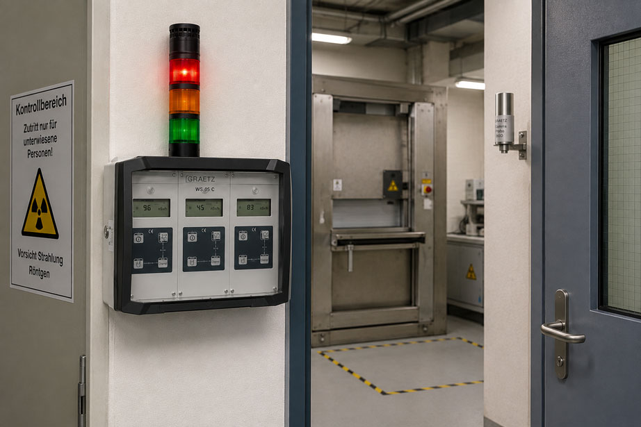
A stationary radiation monitor has been installed, the probe is functioning and the alarm thresholds have been configured.
This should mean that the monitored room is reliably protected.
However, the probe is located behind a massive support structure, while the potential radiation source is positioned on the opposite side of the room.
During normal operation, everything appears plausible.
However, in the event of a local increase in dose rate, this exact geometry can cause the probe to respond considerably later than expected.
This example shows:
In stationary radiation monitoring, the quality of monitoring depends not only on the measuring instrument itself, but particularly on the position of the probe.
A room monitoring system must therefore be considered as a complete measurement and alarm chain:
Radiation source → propagation and shielding → probe → probe cable → area monitor → alarm threshold → relay → warning light / alarm → personnel response
Reliable planning should therefore include, among other things:
- type and position of potential radiation sources,
- radiation type and energy range,
- possible operating and fault conditions,
- personnel occupancy and access areas,
- shielding and structural obstacles,
- measuring range of the probe used,
- normal radiation background,
- pre-alarm and main alarm concept,
- alarm transmission via relays,
- position of external warning lights,
- door contacts or motion detectors,
- behavior in the event of probe failure or power failure,
- regular functional testing.
Particularly important:
There is no universally correct mounting height or universally correct distance from the radiation source.
The probe must measure at a location where a change in radiation can be reliably detected for the respective protection concept.
Stationary area monitors can be found at ICS Schneider under Area Monitors. Further dose-rate measuring instruments, probes and radiation protection instrumentation can be found under Radiation Measurement Technology.
Table of Contents
- What should an area monitor detect?
- Correctly determine the measurement quantity and radiation type
- Distinguish between hazard zones and occupancy areas
- Consider possible source positions
- Correctly assess the distance from the source
- Avoid shielding by walls and equipment
- Distinguish between direct and scattered radiation
- The correct probe mounting height
- Probe at the entrance or near the source?
- When are multiple probes useful?
- Select the appropriate probe measuring range
- Determine radiation background before commissioning
- Define pre-alarm and main alarm thresholds appropriately
- Plan relay logic and alarm transmission
- Position warning lights correctly
- Integrate door contacts and motion detectors appropriately
- Do not confuse alarm relays with safety interlocks
- Route probe cables correctly
- Consider power failure and emergency power supply
- Clearly indicate probe failure and instrument faults
- Commission the system using the actual installation geometry
- Perform regular functional tests
- Document positions and the alarm matrix
- Typical planning and installation errors
- Systematic planning of stationary area monitoring
- Practical example: probe detects a source behind shielding too late
- Suitable ICS products
- Conclusion
- FAQ
What should an area monitor detect?
Before positioning a probe, it must first be defined what task the monitoring system is intended to perform.
A statement such as:
“The room should be monitored for radiation.”
is too general for this purpose.
Possible monitoring objectives include:
- detecting increased dose rates throughout the work area,
- detecting an unexpectedly active source,
- detecting a source outside its intended shielding,
- monitoring an access area,
- indicating the status of an irradiation room outside the room,
- activating a warning light when the dose rate increases,
- transmitting an alarm to a control room.
Depending on the objective, a completely different probe position may be appropriate.
Example: protecting the source area or personnel?
If the main objective is to detect an unusually high dose rate near a technical radiation source, a probe located close to this area may be appropriate.
If, on the other hand, the objective is to prevent personnel from entering an affected room unnoticed, monitoring the access area is also particularly important.
The key question is therefore:
Which radiation condition must be reliably detected before personnel or equipment can be endangered?
Correctly determine the measurement quantity and radiation type
A stationary probe must be suitable for the radiation actually present.
For monitoring gamma and X-ray radiation, the ambient dose equivalent rate is typically used:
Ḣ*(10)
The indication may, for example, be given in:
- µSv/h,
- mSv/h,
- Sv/h.
The suitable probe depends, among other things, on:
- radiation type,
- radiation energy,
- expected dose rate,
- required sensitivity,
- required measuring range.
Pulse rate is not automatically dose rate
With certain probes, the measured quantity is not directly the dose rate but a pulse rate.
The indication may then, for example, be given in:
pulses per second – Ip/s
or:
Ips
The appropriate measurement quantity must therefore already be considered when selecting the probe.
Distinguish between hazard zones and occupancy areas
The highest dose rate is not necessarily located where the probe should be installed.
For the protection concept, two areas are particularly relevant:
area where radiation may be generated
and:
area where personnel may be present or enter the room
Typical relevant locations
The following should be considered during planning, for example:
- workplaces,
- operator stations,
- doors and access locks,
- maintenance access points,
- sample transfer points,
- source or irradiation equipment,
- storage locations for radioactive materials,
- possible source transport routes.
Monitoring only the center of the room is not automatically representative
A probe positioned in the geometric center of the room may initially appear plausible.
However, this position may be unfavorable if:
- the source is regularly used near a wall,
- the room geometry is highly asymmetrical,
- massive shielding lies between the source and the probe,
- the critical occupancy area is located near a door.
The geometric center of a room is therefore not a universally optimal measuring point.
Consider possible source positions
Planning is comparatively straightforward for a stationary source.
The position and orientation of the source are known.
However, in many applications the radiation geometry can change.
Examples include:
- movable sources,
- changing sample holders,
- transport containers,
- medical applications,
- mobile X-ray equipment,
- maintenance and service conditions.
Do not consider normal operation only
At minimum, the relevant operating conditions should be considered during planning:
- normal operation,
- setup,
- source replacement,
- loading and unloading,
- maintenance,
- plausible fault conditions.
A probe that is optimally positioned during normal operation may be unfavorably shielded when the source position changes.
Correctly assess the distance from the source
For gamma and X-ray radiation, distance is a major factor influencing the measured dose rate.
For an idealized point source without relevant shielding or scattering effects, the inverse-square law applies approximately:
Ḣ₂ = Ḣ₁ · (r₁ / r₂)²
where:
- Ḣ₁ = dose rate at distance r₁,
- Ḣ₂ = dose rate at distance r₂.
Simple example
If the distance from an idealized point source is increased from:
1 m
to:
2 m
the dose rate is ideally reduced to approximately:
1 / 2² = 1 / 4
of the original value.
The formula is only an approximation
In real rooms, additional factors include:
- walls,
- ceilings,
- shielding,
- machines,
- scattered radiation,
- extended sources,
- directional radiation fields.
The inverse-square law must therefore not be used as a complete model for real room monitoring.
Do not position the probe unnecessarily far away
If a probe is installed far away from the relevant radiation zone, a local change may disappear into the background or only become clearly detectable at a significantly higher source intensity.
Do not position the probe unnecessarily close to the source
Installation directly next to the normal source can also be unfavorable.
Possible problems include:
- permanently high normal readings,
- frequent warnings during normal operating changes,
- insufficient representation of the personnel occupancy area,
- exceeding the suitable measuring range during fault conditions.
The measuring point must therefore be selected as a suitable compromise between sensitivity, measuring range and protection objective.
Avoid shielding by walls and equipment
One of the most important questions when installing a probe is:
What is located between the potential source and the probe?
Even if two points are only a few meters apart, the following may be located between them:
- concrete wall,
- lead shielding,
- steel structure,
- machine,
- vessel,
- protective cabinet,
- large pipe.
Shielding may be intentional – but problematic for the probe
A radiation shielding wall performs its intended function by reducing radiation.
However, if the monitoring probe is also installed behind this wall, it may only detect increased radiation on the other side in a significantly attenuated form.
Typical planning error
The probe is installed where:
- a power outlet is available,
- the cable can be routed easily,
- free wall space is available.
Only later is it considered whether shielding lies between the probe and the relevant radiation zone.
The mounting position should therefore be derived from the radiation geometry and not primarily from the electrical installation.
Distinguish between direct and scattered radiation
In a real room, the probe is not reached only by direct radiation.
Gamma and X-ray radiation can be scattered by:
- walls,
- floor,
- ceiling,
- machine components,
- patients or objects.
Why this is important for positioning
A probe outside the direct radiation beam may nevertheless detect significant scattered radiation.
Conversely, a change in direct radiation may be strongly reduced by shielding while the scattered radiation field is distributed differently.
Map the room dose rate before final installation
For important applications, it is therefore useful to investigate the dose rate at several potential probe positions using a suitable portable measuring instrument.
The measurements should be performed under defined and representative operating conditions.
Relevant conditions may include:
- normal operation,
- maximum intended operating power,
- different source positions,
- open or closed shielding, where operationally permitted and safe,
- access areas.
This allows the final probe position to be determined much more reliably than from a floor plan alone.
The correct probe mounting height
There is no general rule for stationary radiation probes such as:
“Always install at a height of 1.5 m.”
Such a general rule would not be technically appropriate.
The mounting height depends on the monitoring objective
Relevant factors include:
- height of the potential source,
- radiation direction,
- shielding,
- typical occupancy area,
- possible transport routes,
- mechanical protection of the probe.
Example
A source is permanently located in a process vessel approximately:
0.8 m
above the floor.
At a height of:
2.5 m
there is a massive steel structure.
A probe above this structure could respond less favorably despite being spatially close than a lower-mounted probe with a clearer view of the relevant radiation zone.
Consider mechanical protection
At the same time, the ideal measuring position must not result in the probe:
- being struck by transport carts,
- being damaged during cleaning,
- being easily moved accidentally,
- being obscured by moving machinery.
Measurement requirements and mechanical installation must therefore be considered together.
Probe at the entrance or near the source?
This question cannot generally be answered in favor of one of the two positions.
Probe close to the source
Advantages:
- changes at the source are often detected early,
- high sensitivity to local events.
Disadvantages:
- high normal dose rate may occur,
- limited information about remote occupancy areas,
- possible overrange or unsuitable measuring range.
Probe in the access area
Advantages:
- monitoring of the radiation condition actually relevant before entry,
- good combination with an external warning indicator.
Disadvantages:
- local events close to the source may only be detected at higher intensity,
- shielding between the source and the entrance can reduce the signal.
For large or complex rooms
For critical or geometrically complex applications, the correct solution may therefore be:
multiple spatially separated measuring points
instead of a compromise location for a single probe.
When are multiple probes useful?
Multiple probes can be useful if:
- several rooms are monitored simultaneously,
- several relevant sources are present,
- the source and access point are far apart,
- significant shielding divides the room,
- different measuring ranges are required.
Example with two measuring points
Channel 1:
Probe in the radiation source area
Channel 2:
Probe in the relevant access area
This allows two different monitoring objectives to be covered.
Multiple channels do not automatically mean redundancy
Two probes connected to a multi-channel instrument do not automatically constitute a redundant safety system.
True redundancy would additionally require consideration of, for example:
- common power supply,
- common electronics,
- cable routing,
- common-cause failures,
- alarm transmission.
Multi-channel monitoring and safety-related redundancy should therefore be treated as separate concepts.
Select the appropriate probe measuring range
A probe must reliably measure both the normal range and the relevant elevated dose rate.
Measuring range too high
A probe designed for very high dose rates may have unfavorable sensitivity or resolution in an application with very low ambient values.
Measuring range too low
Conversely, a highly sensitive probe may leave its suitable measuring range in a high radiation field.
The decisive range
The following should therefore be known when selecting the probe:
- natural or operational background,
- typical normal value,
- desired alarm threshold,
- expected fault-condition dose rate,
- maximum dose rate that should reasonably be monitored.
Do not consider only the alarm threshold
The probe should not merely function at the desired alarm threshold.
It must also exhibit defined behavior sufficiently above that threshold so that a significantly higher radiation field does not lead to a misinterpreted measurement condition.
Determine radiation background before commissioning
Before alarm thresholds are defined, it should first be known which values normally occur at the intended probe location.
Background is not the same everywhere
The local value may be influenced by:
- building materials,
- neighboring radiation sources,
- medical or industrial equipment,
- stored radioactive materials,
- changing operating conditions.
Use more than a single snapshot
A single measurement lasting only a few seconds is often insufficient to define a long-term background level.
It is more useful to observe the location over a representative period and under different normal operating conditions.
Do not place the alarm threshold immediately above background
If an alarm threshold is too close to normal statistical or operational fluctuations, unnecessary alarms may occur.
This can result in:
- frequent acknowledgements,
- loss of confidence in the alarm system,
- subsequent raising of the threshold without sufficient assessment.
The alarm threshold should therefore be derived from the radiation protection and operating concept and not merely from:
background + arbitrary margin
Define pre-alarm and main alarm thresholds appropriately
A multi-stage alarm concept can offer advantages over a single alarm threshold.
Pre-alarm
A pre-alarm can indicate, for example, that:
- the dose rate has left the normal operating range,
- a situation should be checked,
- no immediate emergency action is yet required.
Main alarm
A higher alarm level can be linked to clearly defined actions.
Examples may include:
- preventing access,
- leaving the room,
- informing the radiation protection officer,
- checking the operating condition of the source.
No universal alarm values
A general value such as:
“Always trigger an alarm at X µSv/h.”
should not be used for stationary area monitoring.
Suitable thresholds depend, among other things, on:
- application,
- radiation protection area,
- normal dose rate,
- occupancy time,
- risk assessment,
- permit or regulatory requirements,
- operational radiation protection concept.
The thresholds should therefore be defined by the persons responsible for radiation protection or by appropriately qualified personnel.
Consider hysteresis and acknowledgement
For fluctuating values around an alarm threshold, it should also be defined:
- when the alarm is activated,
- when it is reset,
- whether acknowledgement is required,
- whether the alarm is stored.
Otherwise, a warning light may continuously switch on and off when the dose rate fluctuates around the threshold.
Plan relay logic and alarm transmission
A local indication on the area monitor is not sufficient for many systems.
An alarm must be perceived where personnel are able to respond.
Possible alarm destinations
- external warning light,
- audible signaling device,
- control room,
- building management system,
- PLC,
- separate radiation protection indicator.
Define the alarm matrix before wiring
Before installation, it should be documented which message triggers which response.
| Event | Local indication | External message | Intended response |
|---|---|---|---|
| Ready for operation | Status indication | optional | Normal operation |
| Alarm threshold 1 | Visual / audible warning depending on configuration | optional control room | Check situation |
| Higher alarm threshold | Alarm | Warning light / control room | Defined radiation protection action |
| Probe fault | Fault indication | Transmit fault indication | Restore monitoring |
| Power failure | depending on power supply concept | Fault or UPS operation | Check power supply |
Distinguish between alarm and fault
A particularly important distinction is:
radiation alarm ≠ instrument fault
A failed probe must not simply result in:
0 µSv/h
being displayed, causing the user to incorrectly assume a safe condition.
A separate fault indication is therefore an important part of the monitoring system.
Position warning lights correctly
A warning light only fulfills its purpose if the affected person can see it in time.
Warning before entry
For a monitored room, an external indication is particularly useful in the access area.
The status should be recognizable:
before the person enters the monitored area
and not only:
after the door has been opened and the room entered.
Check visibility
The following should be considered during installation:
- line of sight when approaching,
- door opening direction,
- shelves or cabinets,
- lighting,
- multiple access points,
- ambient acoustic conditions.
Multiple entrances
If a room has several access points, a warning light at only one door may be insufficient.
The alarm concept must reflect the actual access arrangement.
Integrate door contacts and motion detectors appropriately
A door contact can provide additional information about the operating condition.
For example, an alarm may be made dependent on whether:
- a door is open,
- a person enters the area,
- a motion detector is activated,
- a light barrier is triggered.
Example
A dose rate exceeds a defined alarm threshold.
The room itself is unoccupied during an intended operating condition.
If the door is then opened, an audible alarm can immediately warn the person entering about the existing condition.
A door contact does not replace radiation measurement
The door contact answers only the question:
Door open or closed?
The probe answers:
What radiation condition exists at the measuring point?
Both pieces of information can be combined effectively, but they serve different purposes.
Do not confuse alarm relays with safety interlocks
A potential-free relay contact on an area monitor can be very useful for alarm transmission.
It can be used, for example, to:
- activate a warning light,
- transmit a message to a PLC,
- notify a control room.
However:
The presence of a relay output does not automatically mean that it may be used to implement a safety-related shutdown of a radiation source.
If the signal is to form part of a technical safety function, the following must additionally be evaluated, among other things:
- required safety integrity,
- failure behavior,
- relay logic,
- cable-break monitoring,
- power failure,
- resetting,
- applicable standards and approvals.
Define fail-safe logic on a project-specific basis
If fail-safe alarming is required, it should be checked, for example, whether an energized-to-healthy principle is appropriate or required.
In this case, not only an active alarm but potentially also:
- cable break,
- power failure,
- instrument failure
would result in a recognizable safe or fault condition.
However, this must be defined and technically verified within the specific safety concept.
Route probe cables correctly
A separate probe enables flexible positioning.
However, the probe cable then becomes part of the monitoring system.
Cable routing
Where possible, the cable should be:
- mechanically protected,
- clearly identified,
- not routed over sharp edges,
- not subjected to unnecessary tensile load,
- not trapped in moving machine parts.
The probe position must not change due to cable tension
A correctly determined measuring position loses its value if the probe is later displaced due to:
- cable tension,
- cleaning work,
- maintenance,
- accidental impact.
The mounting arrangement should therefore ensure a reproducible probe position.
Document long cables
Long probe cables may be required in larger systems.
At minimum, the following should then be documented:
- cable type,
- cable length,
- routing,
- plug connections,
- probe assignment to the measuring channel.
Only cable lengths and components approved by the manufacturer for the respective instrument configuration should be used.
Consider power failure and emergency power supply
Permanent area monitoring is only permanently available if its power supply is also taken into account.
Question for the safety concept
What happens in the event of:
230 V mains failure?
Possible requirements include:
- monitoring must continue,
- the alarm must continue to be output,
- power failure must be indicated separately,
- a controlled system condition must be established.
Do not consider emergency power only afterwards
If uninterrupted monitoring is required, the power supply should already be considered during the planning phase.
This does not only apply to the monitor and probe.
Connected components such as:
- external warning lights,
- audible alarms,
- relay modules,
- communication components
must also be included in the power supply concept.
Clearly indicate probe failure and instrument faults
A monitoring system must not only detect increased radiation.
It must also be apparent if the monitoring system itself is no longer operating reliably.
Possible faults
- probe disconnected,
- probe cable damaged,
- plug connection loose,
- measuring channel faulty,
- power supply failed.
“No measured value” must not look like “no radiation”
This point is particularly important from a safety perspective.
The conditions:
low dose rate
and:
measurement system not operational
must be clearly distinguishable from one another.
Commission the system using the actual installation geometry
After mechanical and electrical installation, it is not sufficient merely to check whether the display shows a plausible background value.
The complete monitoring chain should be evaluated.
Step 1: Check the installation
Verify:
- probe at the intended position?
- correct orientation?
- no new shielding introduced?
- cable mechanically protected?
- correct channel connected?
Step 2: Record the background
Document measured values with the radiation source switched off or in a defined safe condition.
Step 3: Check a representative operating condition
Under the intended safe conditions, verify whether the probe responds to the actual radiation geometry as expected.
Step 4: Check alarm thresholds
Verify:
- correct threshold values,
- correct measuring channel,
- correct indication,
- correct audible warning.
Step 5: Test external signals
Test each relevant relay path separately:
- warning light,
- audible signaling device,
- PLC input,
- control room,
- other indicators.
Step 6: Simulate a fault
Within the framework of the manufacturer and system requirements, it should also be checked how the system responds to defined fault conditions.
Examples include:
- probe fault,
- communication fault,
- power failure.
Perform regular functional tests
An area monitoring system that functions correctly during commissioning does not automatically remain unchanged over time.
The following can change:
- probe position,
- room equipment,
- shielding,
- source positions,
- cables,
- alarm thresholds,
- external alarm system.
Typical scope of testing
Depending on the system and manufacturer, regular tests may include:
- visual inspection,
- status check,
- probe test,
- alarm threshold check,
- test of visual alarm,
- test of audible alarm,
- test of relay outputs,
- test of external warning lights,
- test of emergency power function,
- updating documentation.
Use a radiation source for functional testing only under controlled conditions
If a test source or defined radiation is used for a functional test, this may only be done in accordance with the applicable radiation protection procedures and manufacturer instructions.
Improvised tests using unshielded sources are not a suitable substitute for a documented test procedure.
Document positions and the alarm matrix
A stationary area monitoring system should be documented so that even years later it is possible to understand why a probe was installed at its specific location.
Useful documentation data
- floor plan of the monitored area,
- position of each probe,
- mounting height,
- associated measuring channel,
- probe type,
- measuring range,
- cable length,
- normal background value,
- alarm thresholds,
- alarm matrix,
- relay assignment,
- position of warning lights,
- commissioning measurements,
- date of the last functional test.
Evaluate changes to the room
Particularly important:
If, for example, at a later date:
- a new lead wall is installed,
- a machine is relocated,
- a radiation source is moved to another location,
- a new access point is created,
- a shelving unit is placed in front of the probe,
it should be checked whether the original probe position is still suitable.
A stationary probe monitors the actual radiation geometry, not the original planning drawing.
Typical planning and installation errors
| Observation | Possible cause | Recommended check |
|---|---|---|
| Probe responds only at very high source intensity | Excessive distance or shielding | Check radiation field and probe position |
| Monitor continuously shows a relatively high normal value | Probe too close to the normal source | Reassess location and measuring range |
| Frequent unexplained pre-alarms | Threshold too close to normal operating range | Document background and operating conditions |
| Local source is poorly detected | Massive equipment between source and probe | Check shielding or use a second probe |
| Warning light is barely visible from outside | Unfavorable mounting position | Check the access situation in practice |
| Alarm cannot be heard in the adjacent room | Audible alarm only local | Check alarm transmission and signaling devices |
| Alarm arrives at the wrong PLC address | Relay channel incorrectly assigned | Test alarm matrix and wiring |
| Values are significantly lower after modifications | New shielding between source and probe | Reassess room geometry |
| Measured value suddenly remains very low | Possible probe or cable problem | Check fault indication and probe function |
| System fails completely during mains failure | No suitable emergency power supply provided | Review power supply concept |
| One access point has no warning indicator | Room was expanded later | Include all access points in the alarm concept |
| Probe was moved during cleaning | Insufficient mechanical mounting | Use a reproducible mounting arrangement |
| Relay output is used directly as a machine safety shutdown | Alarm function treated as a safety function | Check safety concept and required approval |
| Multiple probes show different values | Different geometry and shielding | Do not automatically assume a probe fault; check the radiation field |
Systematic planning of stationary area monitoring
The following procedure is recommended for a new area monitoring system:
- Define the monitoring objective: Which condition should be detected?
- Determine the radiation type: Gamma, X-ray or other relevant radiation?
- Define the measurement quantity: Dose rate or pulse rate?
- Identify potential sources: Document location, movement and operating conditions.
- Assess the radiation area: Consider normal operation and relevant deviations.
- Identify occupancy areas: Consider workplaces, doors and maintenance routes.
- Document shielding: Mark concrete, lead, steel and machinery.
- Determine possible probe positions: Do not select only according to available wall space.
- Investigate the radiation field: Where appropriate, compare suitable positions using a portable measuring instrument.
- Select the measuring range: Consider background, normal operation, alarm range and expected maximum values.
- Determine the number of probes: Define one or more relevant measuring points.
- Determine mounting height: Derive it from source geometry and protection objective.
- Plan cable routes: Provide mechanical protection and clear assignment.
- Determine background: Document normal operating values.
- Define alarm thresholds: Derive them from the radiation protection and operating concept.
- Create an alarm matrix: Define which event triggers which message.
- Plan warning lights: Make the status visible before entering the area.
- Consider door contacts: Where appropriate for the intended alarm strategy.
- Check relay functions: Distinguish alarm transmission from safety-related shutdown functions.
- Define fault indications: Consider probe, cable and instrument failure.
- Assess emergency power requirements: Consider the monitor and external alarm equipment together.
- Perform commissioning: Fully test the measurement, alarm and fault chain.
- Create documentation: Record probe location, thresholds and alarm matrix.
- Define inspection intervals: Organize regular functional testing.
- Define change management: Reassess probe position after modifications.
Practical example: probe detects a source behind shielding too late
A stationary area monitor is installed in a laboratory.
During normal operation, the radiation source is located in a shielded work area.
The room entrance is approximately six meters away.
Step 1: Original installation
The probe is mounted on an easily accessible wall.
The position was chosen mainly because:
- a cable tray is already available,
- installation is simple,
- the probe is mechanically protected there.
Step 2: Background measurement
During normal operation, the monitor indicates plausible and stable values.
The installation initially appears to be correct.
Step 3: Functional test under representative geometry
During a planned inspection, the dose rate is measured at several positions in the room.
It becomes apparent that:
A massive steel structure is located between the source and the stationary probe.
The probe is therefore partially located in a shielded area.
Step 4: Comparative measurement
At an alternative wall position with more favorable geometry, a portable dose-rate meter responds much more clearly to changes in the source area.
Step 5: Review the protection objective
It is determined that the area monitoring system must perform two tasks:
- detect unusual radiation in the source area as early as possible,
- indicate an increased radiation condition before personnel enter the room.
Step 6: Provide two measuring points
The final solution uses:
Channel 1 → probe with suitable exposure to the relevant source area
Channel 2 → probe in the relevant access area
The external warning light is located outside the door and is already visible when approaching.
Step 7: Test alarm transmission
During commissioning, the following are tested separately:
- alarm thresholds of both channels,
- audible warning,
- external warning indication,
- relay transmission,
- probe fault indication.
Result
The originally installed area monitor was technically suitable.
The problem was not the measuring instrument, but the position of the probe.
Only by considering the source, shielding, access area and alarm transmission was a functioning measuring instrument turned into a properly designed area monitoring system.
Suitable ICS products for stationary radiation monitoring
GRAETZ WS05C – stationary area monitor
The GRAETZ WS05C available from ICS is designed for permanent monitoring of gamma and X-ray radiation.
Depending on the version, the following are available:
- WS05C-1 with one measuring channel,
- WS05C-2 with up to two measuring channels,
- WS05C-3 with up to three measuring channels.
This allows, for example:
- several rooms,
- several source areas,
- different relevant measuring positions
to be monitored.
Separate display for each channel
Each measuring channel has its own backlit LC display.
When suitable gamma probes are used, the dose rate is displayed in:
Sv/h
.
With corresponding pulse probes, the indication can be provided as a pulse rate.
Four programmable dose-rate alarm thresholds per channel
For each measuring channel, the WS05C allows four dose-rate alarm thresholds to be programmed within the measuring range of the connected gamma probe.
This allows a multi-stage monitoring strategy to be implemented.
However, the actual thresholds used must be derived from the respective radiation protection concept.
Visual and audible warning
The WS05C has an integrated signal tower.
In the standard version, the following states are distinguished, among others:
- Green – ready for operation,
- Orange – alarm threshold exceeded,
- Red – fault indication, for example probe failure.
In addition, a red LED above the respective display indicates which measuring channel has triggered a dose-rate alarm.
External alarm transmission
Optional features include:
- relay outputs for controlling external signal towers,
- potential-free relay outputs for each measuring channel,
- external visual-acoustic signal towers,
- integration of existing warning equipment.
The potential-free relay contacts can therefore be used to transmit status information to a higher-level system.
Whether and how such a signal may form part of a safety-related function must be assessed separately for the respective installation.
Door contact, motion detector and light barrier
Depending on the version, the WS05C alarm system can additionally be combined with information about room access.
For example, an audible alarm when an alarm threshold is exceeded can be combined with:
- an open door,
- a motion detector,
- a light barrier
.
This allows the warning to be specifically adapted to an actual access situation.
Probe cable
Suitable probe cables are available for spatially separated installation of the monitor and probe.
According to the current WS05C configuration, extensions up to:
100 m
are possible.
The standard length is:
1.25 m
The actual cable length used must comply with the approved instrument configuration.
Emergency power supply
An optional:
300 W emergency power supply
is available for uninterrupted operation of the WS05C in the event of a mains failure.
Whether an emergency power supply is required and which additional alarm components must also be supplied depends on the respective safety concept.
GRAETZ probe range
The WS05C can be combined with suitable probes from the GRAETZ probe range.
For gamma dose-rate measurements, probes with different measuring ranges are available.
This is particularly important for area monitoring because, for example:
low dose rate in a laboratory
may require a different probe design from:
high dose rate in a technical radiation area.
Further information can be found under GRAETZ Probe Range at ICS Schneider.
Which configuration is suitable?
| Application | Suitable configuration |
|---|---|
| One individual, clearly arranged room | WS05C-1 with suitable gamma probe |
| Source and access area should be monitored separately | WS05C-2 with two appropriately positioned probes |
| Up to three rooms or measuring points | WS05C-3 |
| Alarm must be visible before entry | WS05C with external signal tower |
| Alarm should be transmitted to a PLC or control system | WS05C with corresponding relay output |
| Access situation should be included in the alarm strategy | WS05C in a suitable version with door contact, motion detector or light barrier |
| Monitoring must continue during mains failure | WS05C with suitable emergency power concept |
| Different dose-rate ranges | Select a suitable probe from the GRAETZ probe range |
Further information can be found under GRAETZ WS05C at ICS Schneider.
An overview of stationary systems can be found under Area Monitors at ICS Schneider.
Conclusion
A stationary area monitor can only provide reliable warning if its probe actually detects the radiation field relevant to the protection objective.
The position should therefore not be determined solely on the basis of:
- available wall space,
- cable length,
- ease of installation.
The decisive factors are:
- source position,
- radiation type,
- distance,
- shielding,
- scattered radiation,
- occupancy area,
- access situation,
- probe measuring range.
Undetected shielding is particularly critical.
A massive wall or machine component between the source and the probe can cause a locally high dose rate to appear significantly lower at the measuring point.
A general mounting height is therefore also inappropriate.
The height must be derived from the actual radiation and installation geometry.
For complex rooms, it may be better to use several measuring points, for example:
source area + access area
instead of selecting a single compromise location.
Alarm transmission is equally important.
A radiation alarm must be:
- visible,
- audible,
- clearly interpretable
where a response is required.
Warning lights should therefore be positioned particularly at access points so that the status can be recognized before entering a monitored room.
Relay outputs allow integration into additional alarm and control systems.
However, they must not automatically be regarded as certified safety interlocks.
Faults must also be clearly distinguishable from normal conditions.
A probe failure must not be interpreted as a low dose rate.
After installation, the complete chain should therefore be tested:
Probe → measuring channel → alarm threshold → indication → audible alarm → relay → external warning light / control system
And finally:
Define the monitoring objective → identify sources and occupancy areas → consider shielding → determine suitable probe positions → select measuring range → record background → define alarm thresholds → plan alarm matrix → position warning indicators before access points → protect cables and power supply → test the complete alarm and fault chain during commissioning → document positions and settings → reassess after structural modifications.
FAQ: Correct Installation of Area Monitors and Radiation Probes
What is an area monitor?
An area monitor is a stationary measuring system for continuous radiation monitoring in a defined area. If specified alarm thresholds are exceeded, a visual, audible or external alarm can be triggered.
Which radiation can be monitored with an area monitor?
This depends on the connected probe. The GRAETZ WS05C is particularly designed for stationary monitoring of gamma and X-ray radiation and can also be combined with suitable pulse probes.
Which measurement quantity is used for gamma and X-ray radiation?
With suitable gamma probes, the ambient dose equivalent rate Ḣ*(10) is typically measured and displayed, for example, in µSv/h, mSv/h or Sv/h.
Where should a radiation probe be installed in a room?
The position must be derived from the monitoring objective, source position, shielding, occupancy areas and measuring range of the probe. There is no universally suitable position.
Should the probe be installed in the center of the room?
Not automatically. The geometric center may be unsuitable if the source, shielding or relevant occupancy areas are arranged asymmetrically.
At what height should the probe be installed?
There is no universal mounting height. The decisive factors are source height, radiation direction, shielding, occupancy areas and mechanical protection requirements.
Should the probe be positioned as close as possible to the radiation source?
Not necessarily. A very close position may respond sensitively to source changes but can also produce high normal readings or poorly represent the relevant occupancy area.
Why is the distance from the source important?
For an approximately point-like source, the dose rate in free space decreases strongly as the distance increases. In real rooms, shielding and scattered radiation additionally influence the result.
What is the inverse-square law?
For an idealized point source, the dose rate is approximately inversely proportional to the square of the distance. At twice the distance, the dose rate is ideally approximately one quarter.
Does the inverse-square law always apply?
No. For extended sources, shielding, scattered radiation or complex room geometries, it can only be used as a limited approximation.
What does shielding mean for a radiation probe?
Shielding means that a radiation-absorbing or attenuating component is located between the source and the probe, such as a concrete wall, lead plate or massive machine.
Why can shielding be dangerous?
The probe may detect a locally significantly increased radiation field much more weakly, causing an alarm threshold to be reached later than intended.
Can a machine affect radiation measurement?
Yes. Massive machine components can shield the radiation field or alter it through scattering effects. Changes to the room should therefore also be evaluated with regard to probe position.
When are multiple probes useful?
Multiple probes can be useful when different rooms, source areas, access points or areas separated by significant shielding need to be monitored.
Are two probes automatically redundant?
No. Multiple measuring channels provide multiple measuring points. Safety-related redundancy additionally requires an assessment of common-cause failures, power supply, electronics and alarm transmission.
How do I select the measuring range of a radiation probe?
The measuring range should adequately cover the normal background, typical operating values, desired alarm thresholds and expected higher dose rates.
Why can an overly sensitive probe be problematic?
In high radiation fields, a probe designed for very low dose rates may leave its suitable measuring range.
Why is a probe with a very high measuring range not always better?
A probe designed for very high dose rates may provide unfavorable sensitivity for the specific task when background and alarm levels are low.
Should the radiation background be measured before commissioning?
Yes. The normal background or operational normal range at the future probe location should be known before the alarm strategy is finalized.
How high should the alarm threshold be?
There is no universal value. The alarm threshold must be derived from the application, normal radiation level, risk assessment, radiation protection concept and, where applicable, regulatory requirements.
What is a pre-alarm?
A pre-alarm can indicate increased radiation before the higher alarm level intended for further measures is reached.
What is a main alarm?
This can refer to a higher alarm level associated with a clearly defined operational or radiation protection response.
What does an alarm relay do?
A relay output can provide an electrical contact for transmitting an alarm or status to external systems such as warning lights, PLCs or control rooms.
Is an alarm relay automatically a safety shutdown?
No. If it is intended to implement a safety-related shutdown, the complete safety function, including failure behavior and required approvals, must be evaluated separately.
Where should a warning light be installed?
For access monitoring, it should be installed so that the condition of the monitored area can be clearly recognized before entering.
What happens if there are multiple doors?
All relevant access points must be included in the alarm and warning concept. A single warning light may be insufficient if there are several independent access points.
Can a door contact be combined with radiation monitoring?
Yes. Depending on the system, information about the door status can, for example, be used to trigger an audible warning when an affected room is opened.
Does a door contact replace a radiation probe?
No. A door contact only detects the condition of the door. A radiation probe measures the radiation condition.
What happens if a probe fails?
A suitable area monitoring system should clearly indicate a fault so that a failure is not incorrectly interpreted as low or absent radiation.
Why is a fault indication important?
Because the safe condition “low dose rate” must be clearly distinguishable from the condition “measurement unavailable.”
How long can a probe cable be?
This depends on the respective measuring system. Probe cable extensions up to 100 m are available for the GRAETZ WS05C. The permissible configuration should be selected according to the manufacturer specifications.
Why must the probe cable be routed with mechanical protection?
Damage to the cable can affect measurement or communication with the probe. Cable tension must also not change the defined probe position.
Does an area monitor require an emergency power supply?
This depends on the safety concept. If monitoring must continue during a mains failure, a suitable uninterruptible power supply is required.
Can the WS05C be operated with emergency power?
An optional 300 W emergency power supply is available for the GRAETZ WS05C for uninterrupted operation during mains failure.
How many probes can the GRAETZ WS05C monitor?
Depending on the version, the WS05C can be operated with one, two or three measuring channels or probes.
How many alarm thresholds does the WS05C provide?
For each measuring channel, four dose-rate alarm thresholds can be programmed when a suitable gamma probe is used.
Does the WS05C have a warning light?
Yes. The system has an integrated signal tower and can additionally be combined with external visual-acoustic warning equipment.
Which colors are used by the integrated WS05C signal tower?
In the standard version, green indicates ready for operation, orange indicates an exceeded alarm threshold and red indicates a fault, such as probe failure.
Can the WS05C control external warning lights?
Yes. Corresponding relay outputs for controlling external signal towers are optionally available.
Does the WS05C have potential-free relay contacts?
Potential-free relay outputs are optionally available for the individual measuring channels.
Can the WS05C be combined with a door contact?
Yes. Depending on the version, the alarm system can, for example, be combined with an open room access point, motion detector or light barrier.
Which probe is suitable for the WS05C?
The suitable probe type depends on the radiation type, energy range, background, alarm threshold and expected maximum dose rate. The WS05C can be operated with different probes from the GRAETZ probe range.
Does stationary radiation monitoring have to be tested regularly?
Yes. The required intervals and tests depend on the system concept, manufacturer specifications, legal requirements and operational procedures.
Does the probe need to be reassessed after modifications?
Yes, if the modification can affect the radiation field. New walls, machines, shielding, source positions or access points can make a previously suitable probe position unsuitable.
How do I check whether the probe position is correct?
The radiation geometry should first be evaluated based on the source, shielding and occupancy areas. For demanding applications, additional measurements at various proposed positions under defined operating conditions may be useful.
What information should I provide when requesting an area monitor?
Useful information includes the radiation type, source, expected dose rate, background, number of rooms or measuring points, required alarm transmission, cable length, warning lights and, where applicable, the required emergency power supply.
Where can I find the GRAETZ WS05C at ICS Schneider?
Further information can be found under GRAETZ WS05C at ICS Schneider.
Where can I find area monitors at ICS Schneider?
An overview can be found under Area Monitors at ICS Schneider.
Where can I find additional radiation measurement technology?
Additional dose-rate meters, warning instruments, probes and radiation protection measurement technology can be found under Radiation Measurement Technology at ICS Schneider.