


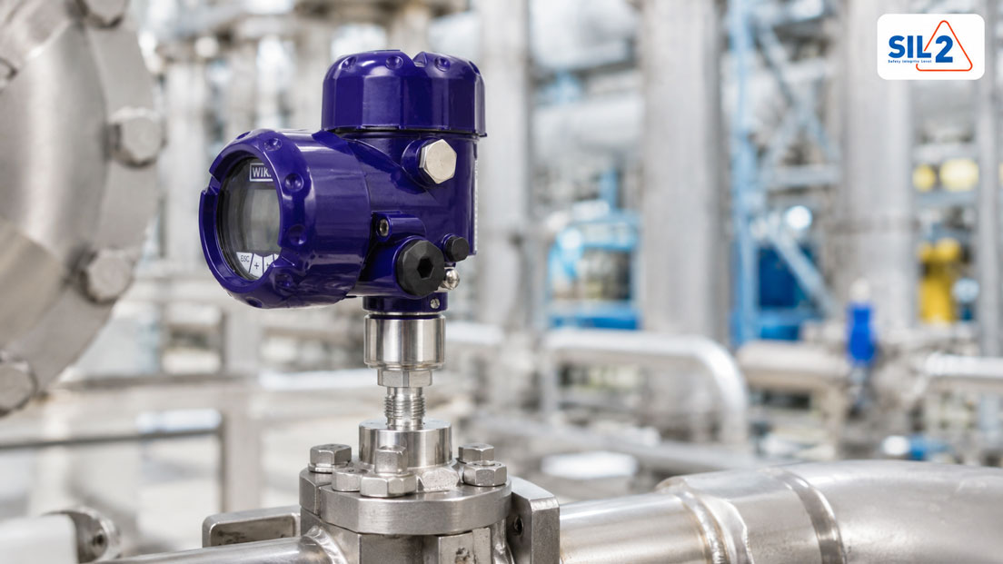
In many process plants, pressure measuring points are not only used for display or control. They can also be part of a safety-related function. A process transmitter then monitors, for example, whether a pressure becomes too high, whether a vessel could be overfilled, whether a pump is operating against a dangerous condition, or whether a plant must be shut down automatically. In such cases, it is not sufficient to simply select an “accurate pressure transmitter”. The measuring point must be considered in the context of functional safety.
The term SIL stands for Safety Integrity Level. It does not simply describe a product property, but the required reliability of a safety-related function. A SIL-capable process transmitter can be an important component, but the SIL of a safety function always results from the interaction of sensor technology, logic, actuators, diagnostics, proof testing, documentation and the design of the complete measuring chain.
This distinction is particularly important for pressure measuring points. A standard pressure transmitter can monitor the process very well and provide a 4–20 mA signal to the PLC or control system. However, as soon as the measured value is intended to trigger a shutdown, interlock or protective function, additional questions must be answered: Is the transmitter suitable for safety-related applications? How are faults detected? What happens in the event of a cable break? How is the proof test performed? And how is it documented that the safety function remains reliable throughout the entire life cycle?
Table of contents
- What does SIL mean for process transmitters?
- Normal process measurement or safety-related measuring point?
- When pressure measuring points become safety-relevant
- Sensor, logic and actuator: SIL applies to the entire safety function
- Selecting the right SIL process transmitter
- Correctly evaluating 4–20 mA, fault current and diagnostics
- HART diagnostics: useful, but not automatically safety-related
- Proof test and recurring inspection
- Documentation, life cycle and responsibilities
- Process connection, diaphragm seal and installation situation
- Typical errors with SIL pressure measuring points
- Practical example: High-pressure shutdown on a process vessel
- Which measuring instruments / products are suitable?
- Conclusion: SIL does not start with the data sheet, but with the safety function
- FAQ: Frequently asked questions about SIL process transmitters
What does SIL mean for process transmitters?
SIL stands for Safety Integrity Level and describes the required level of risk reduction of a safety-related function. In the process industry, this often involves functions designed to prevent or limit hazardous conditions. For example, a pressure measurement value can trigger a shutdown if a pressure limit is exceeded.
It is important to understand that SIL does not simply mean “particularly accurate”. A highly accurate process transmitter is not automatically suitable for a safety-related function. For SIL applications, additional factors are decisive, including failure behavior, diagnostic capability, fault detection, proven-in-use operation, documentation, proof-test capability and integration into the complete safety function.
A process transmitter may be suitable or certified for safety-related applications. However, this does not automatically mean that the entire measuring point achieves a specific SIL. The achievable SIL depends on the complete safety function: from the sensor through the control system to the final element. Architecture, redundancy, proof-test interval and failure probabilities must also be considered.
In practice, precise wording is therefore important. Instead of saying “this transmitter is SIL 2”, it is often more accurate to say: “This transmitter is suitable for use in a safety function up to SIL 2 if the conditions of the manufacturer documentation and the overall safety assessment are fulfilled.”
| Term | Meaning | Important in practice |
|---|---|---|
| SIL | Safety Integrity Level of a safety-related function | Refers to the complete protective function, not only to the sensor. |
| SIF | Safety Instrumented Function | Consists of sensors, logic and final element. |
| SIL-capable transmitter | Transmitter with suitable safety-related characteristic values | Must be selected and documented according to the safety function. |
| Proof test | Recurring test to detect dangerous undetected faults | Test procedure and interval influence the reliability of the safety function. |
| Fault current | Defined current value for signaling a device or measurement fault | Must be correctly evaluated by the PLC, safety controller or control system. |
Normal process measurement or safety-related measuring point?
Many pressure measuring points are used for normal process control. The pressure value is displayed, controlled, logged or used for operator decisions. In such cases, accuracy, long-term stability, process connection, signal quality, media compatibility and ease of operation are the main priorities. A failure may cause production disruptions or measurement errors, but it does not automatically represent a safety-relevant risk.
A safety-related measuring point has a different task. It is intended to prevent a hazardous condition or bring the plant into a safe state. The pressure value is then not merely process information, but an input signal for a protective function. This protective function can, for example, close a valve, shut down a pump, block a heater or bring a plant into a safe state.
The difference therefore lies not only in the device, but in the purpose of the measurement. The same pressure transmitter type may be used in one plant only for indication and in another plant as part of a safety function. What matters is what consequences an incorrect, missing or delayed measured value could have.
During planning, it should therefore first be clarified whether the pressure measuring point belongs to normal process control or whether it triggers a safety-related function. Only then can it be decided whether a SIL-capable process transmitter is required and which requirements apply to diagnostics, proof testing and documentation.
| Feature | Normal process measurement | Safety-related measuring point |
|---|---|---|
| Task | Display, control, monitoring, documentation | Prevention or limitation of a hazardous condition |
| Effect of a fault | Incorrect process value, quality problem or plant malfunction | Possible loss of the protective function |
| Device selection | Accuracy, medium, pressure range, signal, environment | Additionally SIL suitability, failure data, diagnostics and proof test |
| Documentation | Technical data sheet, calibration, parameterization | Additionally safety assessment, test procedure and life cycle documentation |
| Testing | Calibration or functional check | Proof test according to defined test procedure |
When pressure measuring points become safety-relevant
Pressure is a safety-critical process variable in many plants. Excessive pressure can overload vessels, pipelines, seals, pumps, heat exchangers or reactors. Pressure that is too low can also be dangerous, for example in the case of dry running, vacuum, missing barrier fluid, insufficient supply or an incorrect process condition.
A pressure measuring point becomes safety-relevant when its measured value is used to detect a hazardous condition and automatically initiate a protective action. Typical examples include high-pressure shutdowns, low-pressure monitoring, pressure limits on reactors, compressor protection, pump releases, filter monitoring with safety-relevant consequences or monitoring of differential pressures in critical processes.
Not every limit alarm is automatically a SIL function. A warning lamp or a simple operating limit may be part of normal process monitoring. The function becomes safety-relevant when it is designed as a protective measure against a defined risk. This distinction should be clearly described in the risk analysis and safety concept.
The independence of control and protective function is particularly important. If the same measured value is used both for normal control and for safety-related shutdown, it must be checked whether this is permissible and whether common faults could impair the protective function. For this reason, separate measuring points are often used in plants for process control and safety.
Sensor, logic and actuator: SIL applies to the entire safety function
A safety-related function typically consists of three areas: sensors, logic and actuators. The process transmitter is only the sensor part. It detects the pressure condition and outputs a signal. The logic, for example a safety PLC or suitable evaluation unit, evaluates this signal. The final element, for example a valve, contactor, actuator or pump shutdown, brings the process into the safe state.
All three areas must be considered when evaluating the safety function. A highly reliable SIL-capable pressure transmitter is not sufficient if the shutdown valve does not close reliably or the logic does not detect faults correctly. Conversely, a very good safety controller cannot fully compensate for the weaknesses of an unsuitable measuring point.
The architecture also plays a role. A single-channel measurement has different characteristics than a redundant measurement with two or three transmitters. In redundant architectures, measured values can be compared, majority decisions can be made or faults can be detected. However, this also increases planning and documentation effort.
During design, the question should therefore not only be whether an individual transmitter is SIL-capable. The decisive question is whether the complete safety function can achieve the required SIL. This includes failure rates, diagnostic coverage, proof-test interval, common causes, process connection, environmental conditions and the system’s ability to switch to a safe state in the event of faults.
| Part of the safety function | Example | Typical question |
|---|---|---|
| Sensors | SIL-capable pressure or differential pressure transmitter | Is the hazardous process condition detected reliably? |
| Logic | Safety PLC, safety relay or suitable evaluation unit | Is the signal evaluated correctly and are faults detected? |
| Actuators | Shutdown valve, pump, contactor, shut-off valve | Is the process brought safely into the desired state? |
| Diagnostics | Fault current, HART diagnostics, cable monitoring | Which faults are automatically detected? |
| Proof test | Recurring functional test | Which dangerous undetected faults are revealed? |
Selecting the right SIL process transmitter
When selecting a SIL process transmitter, the normal technical requirements must first be fulfilled. These include measuring range, overload resistance, process connection, medium, temperature, material, seal, accuracy, output signal, housing, electrical approval and environmental conditions. A transmitter that is suitable from a safety point of view but does not fit the process is not a good solution.
In addition, the manufacturer’s safety-related information must be considered. This includes, for example, suitability for specific safety functions, relevant failure data, permissible operating mode, parameterization instructions, proof-test requirements and diagnostic information. This information is often found not only in the normal data sheet, but also in additional safety manuals or manufacturer documentation.
The measuring range design is also important. A safety limit value should lie within a sensibly usable measuring range. If a very large measuring range is selected even though only a small critical range is monitored, resolution and accuracy in the relevant range may be unfavorable. If the measuring range is selected too narrowly, overload, saturation or incorrect limit evaluation may occur.
For differential pressure measurements, level measurement via pressure, high-temperature media or aggressive media, selection becomes more complex. Diaphragm seals, capillary lines, valve manifolds, condensate pots or protective measures against pressure peaks may be necessary. These components influence response time, measurement behavior and the test concept and must therefore be included in the safety assessment.
| Selection criterion | Why it is important | Typical error |
|---|---|---|
| SIL suitability | Transmitter must be suitable for the planned safety function | Only “SIL” is noticed in the data sheet, but the boundary conditions are not checked. |
| Measuring range | Limit value must be detected reliably and with sufficient accuracy | Measuring range selected too large or too small. |
| Process connection | Measuring point must safely transmit the process pressure | Blockage, pressure peaks or unsuitable connection underestimated. |
| Diagnostic capability | Faults should be detected and clearly evaluated | Fault current or diagnostic messages are not considered in the control system. |
| Proof-test capability | Recurring test must be practically feasible | Measuring point cannot be tested sensibly during operation. |
Correctly evaluating 4–20 mA, fault current and diagnostics
Many process transmitters transmit the measured value via a 4–20 mA signal. This signal is widely used in process plants and is well suited for robust analog measuring chains. However, in a safety function, not only the normal measured value range is important, but also the behavior in the event of faults.
A 4–20 mA signal can be configured so that fault states are indicated by a defined fault current. Depending on the device and parameterization, the current in the event of a fault may be below or above the normal range. The evaluation system must know exactly which values are to be treated as valid measured values and which values are to be treated as faults.
The incorrect interpretation of fault currents is particularly critical. If the controller interprets a fault current as a normal process value, the safety function can fail or trip unnecessarily. Sensor parameterization, safety PLC, limit logic and diagnostic evaluation must therefore be precisely coordinated.
Cable break, short circuit, undervoltage, burden problems and EMC influences must also be considered. A 4–20 mA loop is robust, but not infallible. For safety-related applications, it should be checked how the complete current loop is monitored and how the plant reacts to implausible signals.
For commissioning and troubleshooting, the UPS4E loop calibrator is a suitable tool. It can measure or simulate mA signals, provide loop supply and help evaluate the transmitter, wiring, analog input and scaling separately. Especially with 4–20 mA safety measuring points, this separation is important because not every fault lies in the sensor.
HART diagnostics: useful, but not automatically safety-related
Many modern process transmitters offer HART communication. HART can be used to read parameters, set measuring ranges, retrieve diagnostic information and check device information. This is very helpful during commissioning, maintenance and troubleshooting because the transmitter provides more information than just the analog 4–20 mA value.
For safety-related functions, however, it must be clarified which information is actually part of the safety function. In many applications, the analog 4–20 mA signal remains the safety-relevant measured value, while HART is used for diagnostics, parameterization or maintenance. Whether and how HART data may be used for safety-related purposes depends on the device, system architecture and manufacturer documentation.
HART diagnostics can help detect problems at an early stage. These include, for example, sensor faults, electronics faults, measuring range exceedance, configuration deviations or internal device messages. This information is valuable, but it does not automatically replace a proof test or the safety-related evaluation of the complete measuring chain.
In SIL applications, it should also be specified who is allowed to change parameters and how changes are documented. An unintended change to the measuring range, damping, fault current behavior or output assignment can directly affect the safety function. Parameterization and change management are therefore an important part of the life cycle.
Proof test and recurring inspection
The proof test is a recurring test intended to reveal dangerous undetected faults. For a pressure transmitter, this can mean, for example, applying defined pressure points and checking whether the transmitter, current loop and evaluation react correctly. Depending on the test concept, only part of the measuring chain or the entire safety function is tested.
A proof test is not automatically identical to a normal calibration. Calibration evaluates the measurement deviation against a reference. A proof test evaluates whether the safety function or part of it functions as required and whether dangerous faults are detected. In practice, both activities may overlap, but they must be distinguished technically.
The proof-test interval influences the reliability of the safety function. The longer a dangerous undetected fault could remain present, the more the safety integrity can be affected. For this reason, test interval, test coverage and test procedure must match the safety assessment.
A good proof test is practical, clearly documented and reproducible. It should be clear which components are tested, which test points are used, which tolerances apply, how the plant is brought into a safe state and how the result is documented. For pressure measuring points, it must also be clarified whether the process pressure is simulated, a test pump is connected or a bypass or valve manifold is used.
| Test aspect | Practical question | Why important? |
|---|---|---|
| Test scope | Is only the transmitter or the entire safety function tested? | Only tested parts contribute to test coverage. |
| Test points | Which pressure values or mA values are tested? | Limit value and measuring range must be sensibly covered. |
| Test interval | How often must the recurring inspection be performed? | The interval influences safety integrity. |
| Test coverage | Which dangerous faults are actually detected? | An incomplete test can create a false sense of safety. |
| Documentation | How is the result recorded in a traceable way? | Important for audits, operator obligations and life cycle management. |
Documentation, life cycle and responsibilities
Functional safety does not end with the installation of a SIL-capable process transmitter. It must be considered throughout the entire life cycle of the plant. This includes planning, selection, commissioning, operation, maintenance, recurring inspection, changes, repairs and decommissioning.
For every safety-related pressure measuring point, it should be documented in a traceable way which function it performs, which limit value applies, which devices are used, which parameters are set and how the test is performed. Changes to the measuring range, damping, fault signaling or control logic must also be controlled and documented.
Responsibilities should be clearly defined. The device manufacturer provides data, safety instructions and technical documentation. The plant designer or operator must evaluate whether the device is suitable for the specific safety function. Maintenance must carry out and document tests correctly. Automation engineering must ensure that signals are evaluated correctly.
A common weak point is the handling of replacement devices. If a defective transmitter is replaced, it is not enough to simply install a mechanically suitable model. Measuring range, output behavior, SIL suitability, parameterization, damping, fault current, HART parameters and proof-test documentation must again match the safety function.
Process connection, diaphragm seal and installation situation
For pressure measuring points, the electrical side is often considered very carefully, while the process connection is underestimated. However, for a safety function it is essential that the process pressure reliably reaches the sensor. Blocked pressure channels, closed valves, frozen impulse lines, contaminated diaphragm seals or incorrect installation can cause the transmitter to output a plausible but incorrect pressure value.
For differential pressure transmitters, valve manifolds, impulse lines, venting, condensate pots and height differences are particularly important. If the high and low sides are swapped, lines are blocked or valves are incorrectly positioned, the safety function can be impaired. Mechanical design and commissioning must therefore be planned just as carefully as electrical signal processing.
Diaphragm seals and capillary lines may be necessary when media are aggressive, hot, viscous, crystallizing or critical from a hygienic point of view. They protect the transmitter, but also influence response time, temperature behavior and the test concept. In SIL applications, it should be checked whether the complete measuring arrangement is suitable for the required function.
Pressure peaks, pulsations and vibrations can also stress the measuring point. A transmitter may be electrically suitable and still fail mechanically at an early stage if pressure surges or unsuitable installation are not considered. For safety-related measuring points, robust process integration is therefore a central part of the design.
Typical errors with SIL pressure measuring points
A common error is assuming that a SIL-capable transmitter alone fulfills the safety function. In reality, the entire safety function must be considered. If logic, actuators, parameterization or proof testing do not match, even a suitable sensor can only help to a limited extent.
Another typical error is the lack of separation between process control and protective function. If the same measured value is used simultaneously for control and shutdown, common faults may occur. Whether this is permissible must be evaluated in the safety concept.
Parameterization is also often underestimated. Measuring range, damping, fault current, HART parameters, limit value and scaling must exactly match the safety function. An incorrectly parameterized transmitter may appear plausible during normal operation, but react too late or incorrectly in a limit situation.
Finally, the proof test is often considered too late. If a measuring point is hardly accessible during operation or no suitable test connection is available, recurring inspection becomes difficult or incomplete. Therefore, the proof test should already be considered during the planning of the measuring point.
| Error | Possible effect | Preventive measure |
|---|---|---|
| SIL understood only as a product property | Complete safety function is not sufficiently evaluated | Consider the SIF consisting of sensor, logic and actuator. |
| Incorrect measuring range | Limit value is detected inaccurately, too late or not at all | Select measuring range according to the safety limit value. |
| Fault current not evaluated | Device fault is interpreted as a normal measured value | Check fault current logic in PLC or safety controller. |
| Damping set too high | Protective function reacts with delay | Evaluate response time and process dynamics. |
| Proof test not practical | Dangerous undetected faults remain undetected | Consider test connection, valve manifold and test procedure already during planning. |
| Mechanical process connection blocked | Transmitter no longer measures the real process pressure | Check process connection, impulse line and maintenance concept. |
Practical example: High-pressure shutdown on a process vessel
A process vessel is pressurized. The normal process control system keeps the operating pressure within a permissible range. In addition, an independent high-pressure shutdown is intended to prevent the vessel from exceeding a critical pressure. At a defined limit value, the shutdown is to close a valve and interrupt the pressure supply.
For normal control, a pressure transmitter is connected to the control system. For the safety-related function, a separate pressure measuring point with a SIL-capable process transmitter is provided. This transmitter sends a 4–20 mA signal to suitable safety logic. The limit value is evaluated there and, when exceeded, the final element is actuated.
During design, it is checked whether measuring range, overload resistance, process connection and medium match the vessel. In addition, fault current behavior, diagnostics, proof-test procedure and test interval are defined. The transmitter is parameterized so that the safety limit value lies within the well usable range of the measuring span and damping does not unnecessarily extend the response time.
The current loop is checked during commissioning. A loop calibrator can be used to simulate a defined mA value in order to check whether the safety logic correctly detects the limit value. In addition, the transmitter is subjected to pressure to verify whether sensor, output signal and evaluation match. The result is documented.
The example shows that selecting the SIL process transmitter is only one part of the task. The complete protective function from process pressure through the measuring point to safe shutdown is decisive.
Which measuring instruments / products are suitable?
For safety-related pressure measuring points, the process transmitters / differential pressure transmitters category is the right starting point. It includes robust transmitters for pressure, differential pressure, level and process applications, depending on the version with 4–20 mA, HART, fieldbus, diagnostics, explosion protection, diaphragm seal options and SIL suitability.
As a specific example, the WIKA IPT-20 / IPT-21 process transmitter may be relevant. It is intended for demanding process pressure measurements and is described on the ICS website, among other things, with explosion protection according to ATEX/IECEx and possible applications up to SIL 2 or SIL 3. Which version is suitable in an individual case must be checked on the basis of the specific measuring point, manufacturer documentation and safety assessment.
For general pressure measuring points, machine applications and plant applications, pressure sensors / differential pressure sensors are also relevant. They are suitable for many process and machine measurements, but are not automatically part of a safety-related function. For SIL applications, it must be specifically checked whether the respective device and the complete measuring chain meet the requirements.
For 4–20 mA current loops, the UPS4E loop calibrator is a useful tool for commissioning, loop checks and troubleshooting. It can measure and simulate mA signals, provide 24 V loop supply and help check the transmitter, wiring, analog input and scaling. Especially with safety-relevant measuring points, clear separation between sensor fault, current loop fault and evaluation fault is important.
For recurring tests and complete pressure calibrations, suitable devices from the pressure calibration technology category may also be required. Depending on the measuring range and medium, pneumatic or hydraulic pressure generation, reference instruments, calibration pumps or mobile calibration solutions may be used.
| Product / area | Typical use | Particularly relevant for |
|---|---|---|
| Process transmitters / differential pressure transmitters | Pressure, differential pressure and level measurement in process plants | Safety-related measuring points, Ex areas, HART and diagnostics |
| WIKA IPT-20 / IPT-21 process transmitter | Robust process pressure measurement | Applications with high requirements, explosion protection and possible SIL suitability |
| Pressure sensors / differential pressure sensors | General pressure and differential pressure measurement | Process monitoring, mechanical engineering, filters, level and control |
| UPS4E loop calibrator | Testing and simulation of 4–20 mA signals | Loop check, commissioning, fault current testing and PLC scaling |
| Pressure calibration technology | Generation and reference measurement of test pressure | Calibration, proof-test preparation and recurring inspection |
Conclusion: SIL does not start with the data sheet, but with the safety function
A process transmitter with SIL suitability can be a central component of a safety-related pressure measuring point. However, the decisive factor is not only the device, but the complete safety function. Sensor, logic, actuator, parameterization, fault behavior, proof test and documentation must all match.
For pressure measuring points, process integration is also particularly important. A blocked process connection, an incorrectly set valve manifold, excessive damping or an unsuitable measuring range design can impair the protective function, even if the transmitter itself is suitable.
For 4–20 mA measuring chains, clean testing of the current loop is essential. With a loop calibrator such as the UPS4E, transmitter signal, wiring, analog input and scaling can be checked specifically. In SIL applications, this does not replace a complete safety assessment, but it helps detect typical errors in the measuring chain at an early stage.
FAQ: Frequently asked questions about SIL process transmitters
What does SIL mean for a process transmitter?
SIL stands for Safety Integrity Level. For a process transmitter, this means that the device may be suitable under certain conditions for use in safety-related functions. However, the SIL of the complete protective function depends on the entire measuring chain.
Is a SIL transmitter automatically safe?
No. A SIL-capable transmitter is only one component. The complete safety function consisting of sensor, logic and actuator must be assessed, documented and tested.
What is the difference between SIL-capable and SIL-certified?
SIL-capable generally describes suitability for safety-related applications. SIL-certified means that corresponding evidence or certificates are available. In each individual case, manufacturer documentation and application must be checked carefully.
When does a pressure measuring point become safety-relevant?
It becomes safety-relevant when the pressure measurement value triggers a protective function, for example a shutdown, interlock or limitation of a hazardous condition.
Is every pressure monitoring system with a limit value a SIL function?
No. A simple alarm or operating limit is not automatically a SIL function. What matters is whether the function is designed as a protective measure against a defined risk.
Can the same transmitter be used for control and safety?
This must be evaluated in the safety concept. Shared use can create common faults. In many applications, control and safety function are implemented separately.
Why is the measuring range so important for SIL pressure transmitters?
The safety limit value must lie within the sensibly usable range of the measuring span. A measuring range that is too large or too small can unfavorably affect accuracy, resolution or overload behavior.
What role does the 4–20 mA signal play?
The 4–20 mA signal transmits the measured value to the controller or safety logic. In safety functions, the fault current behavior must also be correctly parameterized and evaluated.
What is a fault current?
A fault current is a defined current value outside or at the edge of the normal measuring range that signals a device or measurement fault. The evaluation system must detect this condition correctly.
Why is HART useful for SIL transmitters?
HART can provide diagnostic information, device parameters and measured values. It facilitates commissioning and maintenance. Whether HART data are part of the safety function must be checked for the specific application.
What is a proof test?
A proof test is a recurring test intended to reveal dangerous undetected faults. It may concern the transmitter, current loop, logic or the entire safety function.
Is a proof test the same as a calibration?
No. A calibration checks the measurement deviation against a reference. A proof test checks whether the safety-related function or part of it works as required.
Why must the proof test already be considered during planning?
If suitable test connections, valve manifolds or bypass options are not provided, recurring inspection will later become difficult or incomplete.
Which errors occur frequently with SIL pressure measuring points?
Typical errors include incorrect measuring ranges, fault currents not being evaluated, excessive damping, unsuitable process connections, missing proof-test procedures and the assumption that a SIL-capable sensor alone is sufficient.
Can a diaphragm seal be used with a SIL measuring point?
Yes, if it is suitable for the application and included in the safety assessment. Diaphragm seals influence response time, temperature behavior and the test concept.
Why is transmitter damping relevant?
High damping stabilizes the signal, but can delay the response of the safety function. Therefore, damping must match the process dynamics and safety concept.
How do you test a 4–20 mA current loop on a SIL transmitter?
With a loop calibrator such as the UPS4E, the mA signal can be measured or simulated. This allows transmitter, wiring, analog input and scaling to be checked separately.
What must be considered with replacement devices?
Replacement devices must not only fit mechanically. Measuring range, parameterization, fault current, damping, SIL suitability and documentation must again match the safety function.
Who decides whether a transmitter is suitable for a SIL function?
Suitability must be assessed as part of the safety assessment of the plant. Manufacturer information, planners, operators, automation engineering and maintenance must work together.
Can ICS support the selection?
ICS Schneider Messtechnik can support the selection of suitable pressure transmitters, process transmitters, calibration technology and loop testing devices. However, the final safety-related assessment of the specific safety function must be carried out by the responsible specialist departments.