


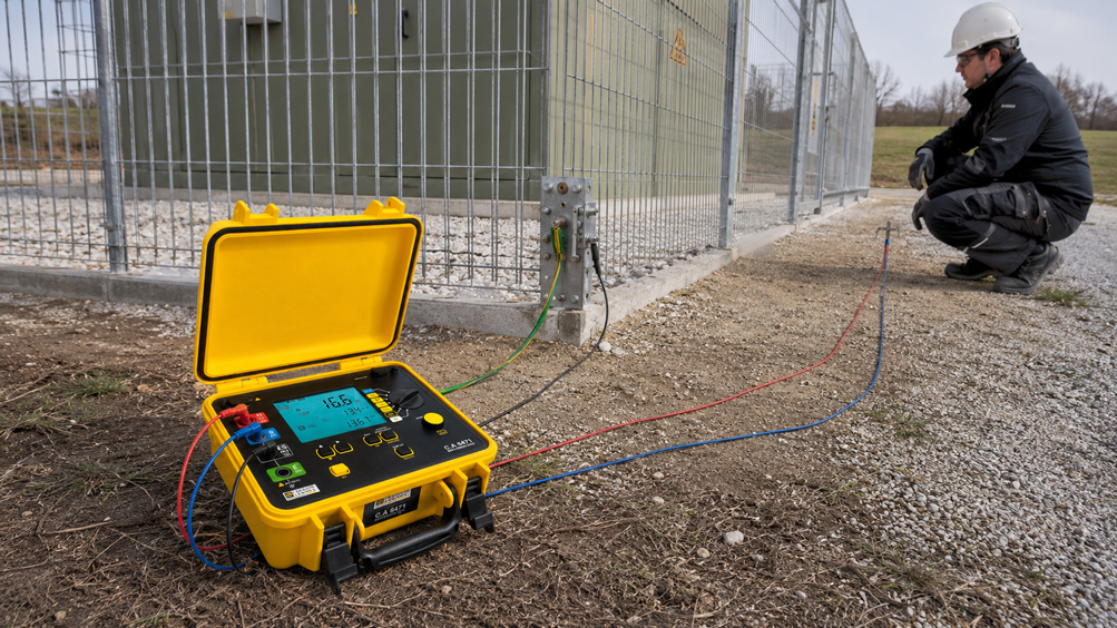
The measured earth resistance of an installation is low, and the connections of the ring earth conductor appear to be electrically continuous. Does this automatically ensure that no dangerous voltages can occur on walkways or at gates, fences, enclosures or operating positions during an earth fault?
No. When an earth-fault current flows, the potential of the earthing system rises relative to remote reference earth. At the same time, a spatial potential distribution develops across the ground surface. As a result, two points only one metre apart can have different potentials. If a person also touches a conductive part, a further potential difference may act across the body.
For a reliable safety assessment, the earthing impedance, relevant earth-fault current, fault duration, surface conditions, potential distribution and possible transferred potentials must therefore be considered together. Suitable test equipment can be found under Electrical Measuring and Test Equipment and Earth and Soil Resistivity Testers.
Important: Measurements on the earthing systems of switchgear installations, transformer substations, overhead-line towers or other power installations may only be performed by appropriately qualified specialists in accordance with an approved measurement, switching and safety plan. Test-current injection can itself create dangerous potential differences and must never be improvised.
Table of contents
- Why an earth fault creates dangerous surface potentials
- Distinguishing between step voltage, touch voltage and earthing voltage
- The purpose of a ring earth conductor
- Why earth resistance alone is not sufficient
- Considering soil resistivity and surface covering
- Measurement concept for step and touch voltages
- Selecting measurement distances and reference earth correctly
- Measuring step voltage
- Measuring touch voltage
- Scaling from test current to earth-fault current
- Selecting critical measurement points systematically
- Controlling interference voltages and 50 Hz influence
- Assessing measured values safely
- Practical example with current scaling
- Typical measurement and assessment errors
- Measures to take if voltages are too high
- Recommended test procedure
- Suitable test equipment from ICS Schneider
- Conclusion
- FAQ
Why an earth fault creates dangerous surface potentials
When current flows through an earthing system into the soil during an insulation fault, a voltage drop occurs across the earthing impedance. In simplified form:
UE ≈ IE × ZE
Where:
UEis the earthing voltage or earth potential rise relative to reference earth,IEis the component of the earth-fault current that actually flows through the earthing system under consideration and into the soil,ZEis the effective earthing impedance.
The total short-circuit or earth-fault current is not automatically identical to IE. Parts of the current may return through cable screens, PEN or protective conductors, pipelines, parallel meshes, adjacent earthing systems or overhead earth wires. The actual current distribution must therefore be considered in the assessment.
A potential gradient develops around the current-carrying earthing system. With a single earth electrode, this is often described in simplified terms as a potential funnel. In extensive earthing grids, ring earth electrodes, meshed systems and arrangements with several metallic return paths, however, the actual potential distribution is considerably more complex. Particularly high gradients can occur at edges, corners, gates, individual extensions and transitions between different ground surfaces.
Distinguishing between step voltage, touch voltage and earthing voltage
| Quantity | Meaning | Typical reference |
|---|---|---|
| Earthing voltage | Potential rise of the earthing system relative to remote reference earth | Earthing system relative to reference earth |
| Step voltage | Potential difference between two points on the ground surface touched simultaneously by a person’s feet | typically two points 1 m apart |
| Touch voltage | Voltage between an accessible conductive part and the location where a person is standing | hand-to-feet current path |
| Transferred potential | Transfer of a potential to another area through conductive connections | for example a fence, pipe, cable screen or rail |
With step voltage, a possible body current flows from one foot through the body to the other foot. With touch voltage, the possible current path may run from the hand through the body to the feet.
The open-circuit voltage measured with a high-impedance voltmeter is not necessarily identical to the body-effective touch voltage. The applicable standard may require a defined load or measuring network that represents body impedance, together with specified contact conditions.
The purpose of a ring earth conductor
A ring earth conductor connects several earthing points and conductive parts of an installation. It can distribute the fault current among several paths, reduce potential differences within the installation and improve equipotential bonding.
Typical functions include:
- connecting foundation, deep and surface earth electrodes,
- integrating transformers, switchgear and cable screens,
- connecting fences, gates and metal structures in accordance with the intended earthing concept,
- reducing local potential differences within the meshed area,
- distributing high fault and lightning currents.
However, a closed ring earth conductor with low resistance does not guarantee safe surface potentials. The potential gradient can be particularly steep at the outer boundary of the ring. Interrupted connections, corroded terminals or unplanned metallic connections can also change the potential distribution significantly.
Particular attention is required at:
- fence gates and fence sections,
- transitions from the installation area to public paths,
- cable routes and metallic pipelines,
- operating positions in front of control cabinets,
- individual deep earth electrodes and earthing extensions,
- connections to adjacent buildings or earthing systems.
Why earth resistance alone is not sufficient
Earth resistance or earthing impedance is an important parameter. However, it does not fully describe how the potential is distributed across the surface or what voltage a person may actually bridge.
Two installations with the same earth resistance can present different risks
Additional decisive factors include:
- the size and geometry of the earthing grid,
- the depth and arrangement of the earth electrodes,
- fault current and current distribution,
- fault-clearing time of the protective device,
- soil resistivity and soil stratification,
- surface covering and moisture,
- the position of accessible conductive parts,
- transferred potentials through extraneous conductive systems.
A low resistance can reduce the earth potential rise. It does not prove, however, that the permissible step or touch voltage is maintained at every accessible location. Conversely, deliberate potential grading with closely meshed earth conductors and a suitable surface covering can reduce local body currents even if the earth resistance itself is not exceptionally low.
Considering soil resistivity and surface covering
Soil resistivity ρ is stated in Ωm. It must not be confused with earth resistance RE, which is stated in Ω.
Soil resistivity depends on factors including:
- soil type and compaction,
- moisture content,
- temperature and frost,
- salt and mineral content,
- soil stratification,
- seasonal changes.
For planning and diagnostics, soil resistivity is often determined using the Wenner or Schlumberger method. Several electrode spacings examine different effective depths and help identify soil layers.
The surface covering is also relevant to the risk to the human body. Gravel, asphalt or other high-resistance surface layers can increase the contact impedance. However, this effect may only be taken into account in accordance with the applicable standard. Contamination, moisture, vegetation, slush or damaged surfaces can significantly reduce the protective effect.
Measurement concept for step and touch voltages
During a controlled measurement, a defined test current is passed through the earthing system and an adequately remote current-return point. At the same time, the local potential differences are measured at specified test points.
A complete measurement concept requires:
- a suitable test-current generator or earth tester,
- a defined current electrode outside the relevant potential zone,
- a reference electrode for measurements relative to reference earth,
- suitable test plates or electrodes for contact with the ground,
- a measuring instrument with an appropriate input impedance or the prescribed body-equivalent network,
- reliable measurement of the test current actually injected,
- a method for suppressing mains-frequency interference and external voltages,
- an installation plan with clearly numbered measurement points.
For large earthing grids or environments with severe interference, the low test current of a handheld instrument may not be sufficient. A dedicated high-current injection system with frequency-selective evaluation may then be required. The measurement method must suit the size of the installation, the interference level and the required verification.
Selecting measurement distances and reference earth correctly
Reference earth is a region whose potential is no longer significantly influenced by the injected test current. For a small individual earth electrode, this region may be relatively close. For a large earthing grid, substation or interconnected line and cable system, substantially greater distances may be necessary.
A fixed distance for current and potential electrodes is therefore not reliable for every installation. The required distance must be derived from the size and geometry of the installation, the expected current distribution and the method used.
The plausibility of the reference point can be checked by:
- moving the potential probe in increments,
- using several measurement lines in different directions,
- looking for a sufficiently flat region of the measurement curve,
- documenting possible parallel return paths,
- routing current and potential leads appropriately in space.
If the current electrode is still within the zone of influence of the earthing system under test, the potential distribution will be distorted. Test leads routed in parallel can also cause errors through inductive or capacitive coupling.
Measuring step voltage
For a step-voltage measurement, two ground contacts are typically arranged at a distance of:
1 m
from one another. They represent the contact areas of both feet. Their design, contact area, applied force and measurement impedance must comply with the applicable test method.
The direction of measurement is decisive
The highest value generally occurs along the steepest potential gradient. The two electrodes should therefore not be positioned in an arbitrary direction. At critical locations, measurements in radial and tangential directions, or in several directions, are advisable.
Typical measurement locations include:
- outside the ring earth conductor,
- at corners and ends of the earthing grid,
- in front of gates and access points,
- at transitions between gravel, asphalt and natural soil,
- along cable and pipeline routes,
- near individual deep earth electrodes.
A single measurement point is not sufficient to assess an entire earthing system. Step voltage must be understood as a spatial quantity and mapped systematically throughout accessible areas.
Measuring touch voltage
For a touch-voltage measurement, the voltage is measured between an accessible conductive part and the location where a person could stand.
Typical accessible parts include:
- enclosures and control-cabinet doors,
- fence sections, gate leaves and gate drives,
- handrails and metallic operating structures,
- tower bases and metal supports,
- pipelines and cable support systems.
The ground contact is positioned in accordance with the specified hand-to-feet scenario, often approximately one metre from the part being touched. The measurement is not simply made relative to an arbitrary protective conductor, but between the accessible part and the defined standing position.
Particular attention must be paid to conductive parts that are not clearly incorporated into the earthing concept. A fence that appears to be isolated may nevertheless be conductively coupled through foundation components, a gate drive, a control cable or vegetation. Conversely, a deliberately separate part may have been connected inadvertently to the earthing grid by a subsequent installation.
Scaling from test current to earth-fault current
The current injected during the test is usually much lower than the possible operational earth-fault current. Provided that the test arrangement is sufficiently linear and representative, the measured voltages are therefore scaled to the relevant earth-fault current.
The scaling factor is:
k = IE / IM
Therefore:
US,F = US,M × k
UB,F = UB,M × k
Where:
IMis the test current actually measured,IEis the relevant earth-fault current component,US,Mis the measured step voltage,UB,Mis the measured touch voltage,US,FandUB,Fare the voltages referred to the fault condition.
Scaling with the total short-circuit current can result in a considerable overestimate or underestimate if only part of that current flows through the earthing system under consideration and into the soil. Current distribution, reduction factors and fault-clearing time must be obtained from the network calculation or the applicable standard.
Selecting critical measurement points systematically
Measurement points should not be selected solely where they are easy to access. All locations where people may stand, walk or touch conductive parts are relevant.
| Area | Possible hazard | Recommended test |
|---|---|---|
| Gate and fence | Transferred potential and touching from outside the installation | Touch voltage inside and outside, step voltage at the transition |
| Operating position | Hand contact while standing on the ground | Touch voltage at the actual standing position |
| Edge of the earthing grid | steep potential gradient | Step voltage in several directions |
| Cable or pipe entry | potential transferred to remote areas | Potential difference relative to local earthing systems |
| Transition between different surfaces | changes in contact impedance and field distribution | Measurement on both surfaces and across the boundary |
| Individual earth electrode or extension | locally high potential gradient | Step-voltage profile along a measurement line |
Controlling interference voltages and 50 Hz influence
In power installations, external voltages and circulating currents are often present even before testing begins. Possible causes include load currents, inductive coupling, parallel lines, railway current, converters and unbalanced networks.
The external voltage should therefore be measured before the test current is injected
If it is too high in relation to the useful signal, the result may fluctuate considerably or become completely unusable. Suitable measurement systems therefore use:
- a test frequency that differs from the mains frequency,
- frequency-selective evaluation,
- polarity reversal or several measurement cycles,
- synchronous acquisition of test current and voltage,
- a sufficiently high test current.
A higher test current improves the ratio between the useful signal and interference, but it also increases the hazard during the measurement. The measuring range, restricted area, communication arrangements, current path and maximum possible test voltage must be defined in advance.
Assessing measured values safely
There is no single limit for step and touch voltages that can always be applied independently of the installation, fault duration and environmental conditions.
The assessment depends in particular on:
- the nominal voltage and type of installation,
- the system configuration and neutral-point treatment,
- the fault current and its distribution,
- the protection and fault-clearing time,
- the current path through the body,
- the contact conditions and surface resistance,
- whether the location is accessible to skilled personnel or the public,
- the applicable standards and operator requirements.
For power installations above 1 kV in Germany, the current DIN EN 50522 (VDE 0101-2) is particularly relevant. Other or additional standards apply to low-voltage installations, lightning-protection systems, railway installations and special operating locations.
A frequently quoted value of 50 V AC must therefore not be used indiscriminately as a universal limit for every earthing system. Depending on the fault duration, measurement method and specified contact conditions, permissible voltages may have to be determined differently.
Practical example with current scaling
A test current of:
IM = 5 A
is injected into a ring earth conductor.
The following values are measured at a gate:
Step voltage US,M = 0.42 V
Touch voltage UB,M = 1.15 V
The network calculation gives the following current component flowing through the earthing system and into the soil for the fault condition under consideration:
IE = 800 A
The scaling factor is:
k = 800 A / 5 A = 160
This gives the following values for the fault condition:
US,F = 0.42 V × 160 = 67.2 V
UB,F = 1.15 V × 160 = 184 V
These values do not yet constitute a final test result. They must be compared with the permissible values for the specific installation, taking the fault-clearing time, contact conditions and measurement uncertainty into account.
However, the example shows why low measured voltages are not automatically harmless. Scaling to the actual earth-fault current can result in considerably higher fault-condition voltages.
Typical measurement and assessment errors
| Error | Effect | Better approach |
|---|---|---|
| Measuring earth resistance only | local potential gradients remain unknown | Add step- and touch-voltage measurements at critical locations |
| Using the total short-circuit current for scaling | incorrect fault-condition voltage | Determine the actual earth-fault current component and return paths |
| Positioning the current electrode too close | potential fields overlap | Increase the distance and check the measurement curve |
| Measuring step voltage in only one direction | the maximum gradient may be overlooked | Test several directions and measurement lines |
| Using an arbitrary digital multimeter | contact and body impedance are not represented in accordance with the standard | Use the specified measuring network and suitable electrodes |
| Failing to measure external voltage | unstable or systematically incorrect values | Measure the interference level in advance and use a selective method |
| Testing only under dry summer conditions | seasonal extreme conditions remain unconsidered | Document moisture, frost and surface condition |
| Overlooking a fence or pipeline | dangerous transferred potential remains undetected | Include all conductive entries and exits in the measurement concept |
| Applying 50 V as a blanket limit | the standard, fault duration and contact conditions are ignored | Determine the permissible voltage for the specific installation |
Measures to take if voltages are too high
If impermissible or unusually high values are found, the cause must be narrowed down by analysing the potential distribution and current paths.
Possible technical measures include:
- extending the earthing grid or increasing its mesh density,
- adding deep, ring or radial earth electrodes,
- repairing corroded or interrupted connections,
- potential grading at edges, gates and operating positions,
- suitable high-resistance surface coverings,
- adapting the equipotential bonding arrangement,
- controlled separation or integration of conductors that transfer potential,
- reducing the protection fault-clearing time,
- restricting access to or relocating accessible areas.
It is not possible to decide generally whether a fence, pipeline or other conductive part should be connected or separated. An incorrect measure can create a new touch voltage or transferred potential. The change must therefore be planned, documented and subsequently verified by a new measurement.
Recommended test procedure
- Define the test objective: Initial verification, periodic verification, fault analysis or verification after modification.
- Determine the applicable standard: Clarify the type of installation, voltage level and operator requirements.
- Obtain the documentation: Collect the earthing plan, network calculation, protection times, earth-fault current and known return paths.
- Prepare a risk assessment: Define the test current, possible test voltages, work area and barriers.
- Perform a visual inspection: Record connections, corrosion, modifications, fences, gates, cables and pipelines.
- Check continuity: Test the ring earth conductor and equipotential bonding at suitable points.
- Document soil and surface conditions: Record moisture, temperature, surface covering and special conditions.
- Plan the test-current circuit: Position the current electrode and route the leads outside critical areas.
- Measure external voltages: Record the interference level before injecting the test current.
- Inject the test current: Measure the actual current stably and synchronously.
- Verify reference earth: Move the potential probe and check the plausibility of the measurement curve.
- Map step voltages: Measure critical areas in several directions.
- Measure touch voltages: Reproduce the actual standing and touch points.
- Check transferred potentials: Include fences, pipes, screens and remote structures.
- Scale the measured values: Scale them to the relevant earth-fault current component.
- Consider measurement uncertainty: Assess current stability, interference level, contacts and repeatability.
- Compare with permissible values: Include the fault duration and contact conditions.
- Locate deviations: Evaluate potential profiles and current paths together.
- Implement corrective measures and repeat the measurements.
- Document the test: Record the setup, weather, measurement points, raw values, scaling and assessment in full.
Suitable test equipment from ICS Schneider
C.A 6472 – Earth and soil resistivity tester with earth-potential measurement
The C.A 6472 combines several methods for investigating complex earthing systems. These include:
- 3-pole earth measurement up to 10 kΩ,
- 4-pole and selective 4-pole measurement,
- earth-loop measurement with two current clamps,
- earth-coupling measurement,
- soil resistivity measurement using the Wenner or Schlumberger method,
- earth-potential measurement,
- continuity and resistance measurement,
- adjustable measurement frequencies for analysis and interference suppression.
The C.A 6472 is therefore particularly suitable for earth resistance, soil analysis and potential profiles. For complete standards-based verification of step and touch voltages, the appropriate current-injection setup, suitable contact plates or measuring networks, current scaling and the installation-specific assessment method must also be defined.
C.A 6471 – Earth, soil resistivity and coupling measurements
The C.A 6471 supports conventional earth measurements, selective methods, earth-coupling measurements and soil resistivity measurements. Its measurement-frequency range from 41 to 512 Hz supports the selection of a suitable frequency in environments with interference.
The instrument provides a suitable basis for determining key earthing parameters. However, it does not automatically replace a complete high-current system for measuring step and touch voltages at large power installations.
C.A 6474 – Supplement for overhead-line towers
The C.A 6474 is an adapter for the C.A 6472 for the selective investigation of overhead-line tower earthing. It is intended for tower and pylon applications and is not a standalone universal tester for arbitrary ring earth conductors.
Further instruments and accessories can be found in the Earth and Soil Resistivity Testers at ICS Schneider category.
Conclusion
Step and touch voltages result from the spatial potential distribution when an earth-fault current flows through an earthing system into the soil. A continuous ring earth conductor with low resistance is important, but is not sufficient on its own for the safety assessment.
The earth-fault current component is decisive
The entire short-circuit current does not necessarily flow through the earth electrode. Cable screens, protective conductors, overhead earth wires and other metallic return paths influence the current distribution.
The measurement is spatial
Step voltage, touch voltage and transferred potential must be investigated at all critical access points, operating positions and boundary areas.
Low test voltages must be scaled
The measured values must be scaled to the fault condition using the ratio between the relevant earth-fault current and the test current actually injected.
A universal limit is not sufficient
The permissible voltage depends, among other things, on the installation, fault duration, contact conditions, surface and applicable standard.
In practice
Check the earthing plan and network calculation → determine the actual earth-fault current component → define the measurement and safety concept → position the current and potential electrodes correctly → measure external voltages → inject a defined test current → measure step and touch voltages at critical points → include transferred potentials → scale the measured values to the fault condition → consider the fault-clearing time and permissible values specified by the applicable standard → plan corrective measures → repeat the measurements after the modification and document everything in full.
FAQ: Step and Touch Voltages at Earthing Systems
What is step voltage?
Step voltage is the voltage difference between two points on the ground surface that a person touches simultaneously with both feet. A distance of 1 m is typically used for the measurement.
What is touch voltage?
Touch voltage exists between an accessible conductive part and the point where a person is standing. It can cause current to flow from the hand through the body to the feet.
What is the potential funnel?
The term describes the spatial decrease in earth potential as the distance from a current-carrying earth electrode increases. In large or meshed earthing systems, the actual distribution is often more complex than a symmetrical funnel.
What does earth potential rise mean?
It is the voltage to which an earthing system rises relative to remote reference earth when an earth-fault current flows.
Is a low earth resistance sufficient as proof of safety?
No. It does not fully indicate how the potential is distributed across the surface or what step or touch voltages occur at individual locations.
Why are step-voltage electrodes placed 1 m apart?
The distance represents a typical step length and therefore the possible foot-to-foot current path. The specific electrode and loading conditions depend on the applicable method.
Can I measure touch voltage with a standard multimeter?
A multimeter can indicate existing potential differences. For standards-based verification, however, a defined input impedance or human-body equivalent circuit and a specified ground electrode may be required.
Why is reference earth important?
It serves as an almost unaffected reference potential. If the reference electrode is still within the potential field of the earthing system, the earthing voltage and potential profile will be measured incorrectly.
How far away must the current electrode be?
There is no fixed distance suitable for every installation. The required distance depends on the size, geometry, soil and connected return paths. The arrangement must be verified by plausibility measurements.
Why is the measurement performed at a frequency other than 50 Hz?
A different test frequency and frequency-selective analysis help distinguish existing power-frequency interference voltages from the actual measurement signal.
Why is the test not performed directly with the full earth-fault current?
The actual fault current can be very high and dangerous. A smaller, controlled test current is therefore usually injected, and the result is subsequently scaled to the relevant earth-fault current.
Which current must be used for scaling?
The relevant value is the current component that actually flows through the earthing system and the soil in the fault scenario under consideration. The total short-circuit current is not automatically the correct value.
Is 50 V AC always the permissible limit?
No. The permissible step or touch voltage depends on the applicable standard, fault duration, contact conditions and type of installation. A blanket comparison with 50 V can lead to an incorrect assessment.
What role does the fault-clearing time play?
The physiological effect of current flowing through the body depends on its magnitude and duration. The protective fault-clearing time is therefore an essential part of the assessment.
Why can gates and fences be particularly critical?
They are accessible, are often located at the edge of the earthing grid and can transfer an installation potential into publicly accessible areas.
Can gravel reduce the risk associated with touch voltage?
A suitable high-resistance surface layer can increase the contact impedance. Its effectiveness must, however, be assessed in accordance with the applicable standard and also considered under wet, contaminated and aged conditions.
When should soil resistivity be measured?
It is important for the planning, expansion and diagnosis of earthing systems. Measurements at several spacings help assess the soil stratification and determine suitable earth-electrode depths.
Why are several measurement directions necessary?
The steepest potential gradient does not run in the same direction at every location. A single orientation can miss the maximum step-voltage value.
Which measured values must be documented?
At a minimum: the measurement setup, electrode positions, test current, raw voltage readings, interference voltages, scaling factor, fault-current assumptions, fault-clearing time, soil and weather conditions, measurement uncertainty and the basis of assessment.
When is a dedicated high-current measurement system required?
For large earthing grids, high interference levels or required standards-based verification, a higher test current evaluated selectively by frequency may be necessary. This must be specified in the measurement concept.
When must measurements be repeated after a modification?
After changes to the earthing grid, fences, cables, pipelines, surface layers or protection times, measurements should verify whether the intended measure actually reduces the step and touch voltages sufficiently.
Keywords
step voltage, touch voltage, earthing system, ring earth conductor, ring earth electrode, earthing grid, earth resistance, earthing impedance, earth potential rise, potential funnel, transferred potential, fault current, earth-fault current, soil resistance, soil resistivity, reference earth, equipotential bonding, earth measurement, C.A 6472, C.A 6471, C.A 6474
Featured Image Prompt
Photorealistic, professional featured image in 16:9 landscape format. Scene at an outdoor European medium-voltage or industrial installation: In the foreground, a robust, unbranded earth tester sits in an open protective case on dry, realistically textured ground. Two heavy metal step-voltage measurement plates lie in a perfectly straight line on the ground, visibly spaced a plausible 1 m apart, and are connected to the tester with neatly routed test leads. To one side is a metal installation fence with a closed gate as a realistic critical area, but without any additional or ambiguous test lead. In the background, a transformer substation, a ring-earth-conductor test point and remote auxiliary earth electrodes are subtly visible. A qualified test technician wearing neutral protective clothing, a hard hat and safety footwear monitors the cordoned-off measurement area without touching any live conductors. Realistic proportions, correct connections, a European industrial setting, clear cable routing without unnecessary loops, neutral bright lighting and high technical credibility. No logos, no brands, no yellow multimeters, no US power outlets, no sparks, no exposed live parts, no text overlays, no arrows, no formulas and no labels in the image.