


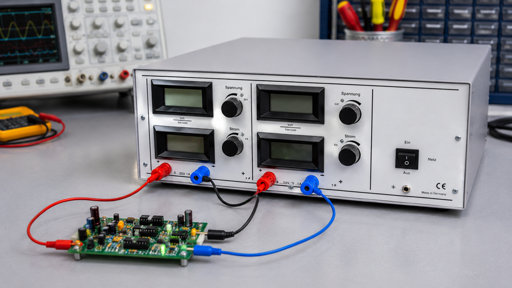
Operational amplifiers, measurement amplifiers, active filters and many other analog circuits require not only a single positive supply voltage but a symmetrical power supply. Typical requirements are, for example, +12 V / 0 V / -12 V or +15 V / 0 V / -15 V. This type of supply is still widely used today, particularly in older analog circuits, precision measurement amplifiers and development setups.
At first glance, generating a negative supply voltage may seem more complicated than providing a normal DC supply. In fact, no special “negative power supply” is required. If a suitable laboratory power supply has two separate outputs that are approved for series operation, the two voltage sources can be connected in series. The electrical connection point between the two outputs is then used as the common 0 V reference. Relative to this midpoint, one supply rail is positive and the other is negative.
For a ±15 V supply, for example, both power supply channels are set to 15 V each. When they are then correctly connected in series, there is a total of 30 V between the two outer terminals. If the connection point between the two sources is defined as 0 V, +15 V and -15 V are obtained relative to this reference point.
A tracking function is not essential for this purpose. It can make operation more convenient because both voltages can be changed together. However, something else is decisive: the laboratory power supply used must explicitly support series operation of its outputs. Equally important are the correct selection of the midpoint, suitable current limits and a well-defined grounding and reference concept. Unexpected ground connections can occur particularly when an oscilloscope is connected.
A symmetrical ±15 V supply therefore does not consist of one “positive” and one special “negative” voltage source. Two normal, suitable DC voltage sources are connected in series. Only the choice of their connection point as 0 V creates the +15 V and -15 V potentials relative to this reference.
Suitable devices can be found under Power Supplies at ICS Schneider and Multi-Output Sources / Laboratory Power Supplies.
Table of Contents
- Why Do Analog Circuits Require Positive and Negative Supply Voltages?
- What Does ±12 V or ±15 V Mean?
- How Are Symmetrical Voltages Generated from Two Power Supply Outputs?
- How to Wire ±15 V Correctly
- How Is the Common 0 V Point Created?
- Check the Voltages Correctly Before Connecting the Circuit
- What Is Tracking and Is It Required?
- What Requirement Must the Laboratory Power Supply Meet?
- Understanding Current Consumption with a Symmetrical Supply
- Setting the Current Limits of Both Channels Correctly
- What Happens If One Output Switches to CC Mode?
- Distinguishing 0 V, Ground and Protective Earth
- Caution When Connecting an Oscilloscope
- Why 30 V Total Voltage Does Not Yet Prove Correct ±15 V
- Asymmetrical Loading of the Supply Rails
- Consider Power-On and Power-Off Behavior
- Practical Example: Operational Amplifier Circuit with ±15 V
- Typical Fault Patterns
- Recommended Connection Procedure
- Suitable Laboratory Power Supply at ICS Schneider
- Conclusion
- FAQ
Why Do Analog Circuits Require Positive and Negative Supply Voltages?
Many analog circuits process signals that lie both above and below a defined reference potential. A typical sensor or laboratory signal may, for example, cover a range from -5 V to +5 V. A conventionally designed operational amplifier circuit can process such positive and negative signal values particularly easily when both a positive and a negative supply rail are available.
A typical supply is therefore +15 V / 0 V / -15 V. The operational amplifier can then process its input and output signals around the common 0 V point without first having to create an artificial midpoint within a single supply voltage.
This type of supply is not limited to operational amplifiers. It is also used for instrumentation amplifiers, active filters, measurement amplifiers, strain-gauge signal conditioning, analog control circuits, audio electronics and numerous laboratory and development setups. Modern circuits can often operate from a single supply with a virtual midpoint. However, if a module is explicitly designed for ±12 V or ±15 V, a true symmetrical supply is often the clearer technical solution.
What Does ±12 V or ±15 V Mean?
A symmetrical supply has three relevant potentials. With ±15 V, these are +15 V, 0 V and -15 V. It is important to understand that the positive and negative voltages are always referenced to the common midpoint.
There are 15 V between the positive supply rail and 0 V. There are also 15 V between 0 V and the negative supply rail. Between the two outer supply rails, however, the voltage is 30 V. With a ±12 V supply, the total voltage is correspondingly 24 V.
| Measurement Points | ±15 V Supply | ±12 V Supply | Meaning |
|---|---|---|---|
| V+ to 0 V | +15 V | +12 V | positive supply rail |
| V- to 0 V | -15 V | -12 V | negative supply rail |
| V+ to V- | 30 V | 24 V | total voltage of both sources |
For the total voltage, the simplified relationship is Utotal = U+ + |U-|. It should be noted that a correct total voltage alone does not prove that the two supply rails are actually symmetrical around the midpoint.
How Are Symmetrical Voltages Generated from Two Power Supply Outputs?
Assume that a suitable dual-channel laboratory power supply has two separate outputs, both set to 15 V. Each channel initially provides a normal positive DC voltage of 15 V between its positive and negative terminals.
For series operation, the negative terminal of output 1 is connected to the positive terminal of output 2. This connection point then forms the common 0 V reference. The remaining positive terminal of output 1 is at +15 V relative to this midpoint, while the remaining negative terminal of output 2 is at -15 V relative to the same point.
The negative voltage is therefore not created because the second power supply channel “generates a negative voltage”. There are still 15 V between its own terminals. Only by defining the common connection point as the reference potential does the outer terminal become -15 V relative to this midpoint.
How to Wire ±15 V Correctly
If an analog module has the supply terminals V+, GND and V-, it must be connected to three points of the series circuit. The positive outer terminal supplies V+, the connection point between the two sources is connected to GND, and the negative outer terminal supplies V-.
| Laboratory Power Supply | Connection on the Analog Circuit | Potential Relative to GND |
|---|---|---|
| Output 1 (+) | V+ | +15 V |
| Output 1 (-) connected to Output 2 (+) | GND / 0 V | 0 V |
| Output 2 (-) | V- | -15 V |
The midpoint is not merely an internal connection between the two power supply channels. A separate wire must also be run from this exact point to the 0 V or GND terminal of the module. Without this connection, the circuit has no defined reference potential.
How Is the Common 0 V Point Created?
The common 0 V point is not an additional voltage regulator and not a special output of the power supply. It is created by the electrical connection of the two voltage sources connected in series.
If two 15 V sources are connected in series, there are 30 V between the two outer ends. Which point within this series circuit is regarded as 0 V then determines the potentials of the remaining terminals. If the connection between the two sources is defined as the reference, one side is 15 V above and the other 15 V below this potential.
This midpoint is connected to the reference specified in the circuit documentation, for example GND, 0 V or AGND. It is important not to automatically equate the circuit reference with protective earth. Whether the 0 V point may or should additionally be grounded depends on the power supply, the measurement concept and the circuit being powered.
Check the Voltages Correctly Before Connecting the Circuit
Before a sensitive analog circuit is connected to the prepared supply, the series connection should be checked with a multimeter. This allows an incorrectly selected midpoint, reversed polarity or unequal voltage settings to be detected before the module is exposed to them.
| Measurement | Black Test Lead | Red Test Lead | Expected Value at ±15 V |
|---|---|---|---|
| Positive supply | 0 V | V+ | +15.0 V |
| Negative supply | 0 V | V- | -15.0 V |
| Total voltage | V- | V+ | 30.0 V |
The analog circuit should only be connected once all three measurements are plausible. The two individual measurements relative to the midpoint are particularly important. A total voltage of 30 V alone is not sufficient verification.
What Is Tracking and Is It Required?
Tracking is a convenience function available on certain multi-channel laboratory power supplies. With a corresponding device, one channel can act as the master output while the second channel follows its voltage setting. If, for example, the master channel is changed from 15 V to 12 V, the second channel can automatically follow to 12 V with 1:1 tracking.
For a symmetrical power supply, this means that a supply such as ±15 V can conveniently be changed to ±12 V without having to adjust both channels separately. Electrically, however, this function is not necessary.
If the laboratory power supply has two independently adjustable outputs that are suitable for series operation, both channels can simply be set separately to the same voltage value. For a fixed ±15 V supply, approval for series operation is therefore much more important than a tracking function.
What Requirement Must the Laboratory Power Supply Meet?
Not every device with two output channels may automatically be connected in series. The manufacturer’s explicit approval is decisive. The outputs must be suitable for the intended series operation with regard to their galvanic and potential characteristics.
Internal ground or earth connections in particular can prevent the desired series connection. In addition, permissible voltages of the output terminals relative to earth must not be exceeded. Connecting unsuitable outputs in series without checking can therefore lead to malfunctions, unwanted earth connections or, in the worst case, a short circuit or damage.
For the 2228.1 DC voltage regulator described further below, series and parallel connection of the two outputs is explicitly specified in the product data.
Understanding Current Consumption with a Symmetrical Supply
Symmetrical voltage does not automatically mean symmetrical current consumption. An analog circuit may, for example, draw 120 mA from the positive supply and only 80 mA from the negative supply. This is not inherently a fault.
The different current demand may result from the internal design of the circuit. What matters is that each power supply channel can reliably provide the current required by its respective supply rail while maintaining a stable output voltage.
The current displays of both power supply channels therefore provide not only operating information but also valuable diagnostic data. If the current consumption of one rail changes unexpectedly, this may indicate a fault in the connected module.
Setting the Current Limits of Both Channels Correctly
When commissioning a sensitive analog circuit for the first time, the current limits should not automatically be set to the maximum output current of the power supply. A limit that is above the expected normal operating current but still restricts the available energy in the event of a wiring or component fault is more appropriate.
Not only the steady-state operating current must be taken into account, but also possible inrush currents and capacitances on the supply rails. A circuit that requires 90 mA during normal operation may briefly draw more current when switched on. If the current limit is set too tightly, the relevant power supply channel may enter constant-current mode during a perfectly normal startup.
The correct setting is therefore a compromise between protection and reliable startup behavior. With unfamiliar modules, it is advisable to monitor the actual current consumption in a controlled manner and adjust the limit step by step to suit the application.
What Happens If One Output Switches to CC Mode?
A regulated laboratory power supply normally operates in constant-voltage mode, abbreviated CV – Constant Voltage. As long as the connected circuit requires less current than the set current limit, the channel maintains its specified output voltage.
If the current limit is reached, the channel switches to constant-current mode CC – Constant Current. The power supply then reduces its output voltage so that the set maximum current is not exceeded.
With a symmetrical supply, one rail can therefore collapse while the other continues to operate correctly. Instead of the original +15 V / 0 V / -15 V, the system could, for example, become +15 V / 0 V / -7 V. An operational amplifier circuit supplied in this way may go into saturation, develop incorrect operating points or fail to start correctly.
If a symmetrical supply unexpectedly becomes unbalanced, the voltage settings should not be the only thing checked. The current consumption and the CV/CC operating state of both power supply channels are equally important.
Distinguishing 0 V, Ground and Protective Earth
The common 0 V point of a symmetrical supply is initially only the electrical reference potential of the connected circuit. It is not automatically connected to PE – Protective Earth.
With floating or appropriately designed power supply outputs, the complete output system may initially be electrically isolated from earth. Within the permissible operating conditions, it can then be deliberately determined whether a specific point should be connected to earth.
Whether the midpoint of the symmetrical supply is grounded depends on the circuit and measurement concept. Such a connection should only be made if it is technically intended and if no other instruments create unintended additional earth connections.
Circuit GND, 0 V and protective earth serve different electrical functions and should therefore not automatically be treated as identical.
Caution When Connecting an Oscilloscope
A laboratory setup may operate correctly and then behave completely differently as soon as a bench oscilloscope is connected. The cause is often not the signal being measured, but the ground connection of the oscilloscope.
On many mains-powered bench oscilloscopes, the ground of the BNC inputs and probes is connected to protective earth. Connecting the probe ground clip to a point in the circuit therefore also connects that point to earth potential.
If, for example, the midpoint of the ±15 V supply is already deliberately connected to PE and the oscilloscope ground is then accidentally connected to the -15 V rail, a connection between -15 V and PE is created through the oscilloscope. Depending on the setup, this can cause a short circuit or force the relevant power supply channel into current limiting.
Before connecting an oscilloscope, it must therefore be clarified which points of the existing setup already have an earth reference. For measurements between non-earthed potentials, suitable differential measurement techniques may be required depending on the application.
Why 30 V Total Voltage Does Not Yet Prove Correct ±15 V
A common verification error is to measure only between the two outer supply rails. If the multimeter shows 30 V there, this only proves that the sum of the two partial voltages is 30 V.
A distribution of +10 V / 0 V / -20 V also produces a total of 30 V between the outer rails, but would be incorrect for a circuit designed for ±15 V. The positive and negative supplies must therefore always be checked separately relative to the common midpoint.
Measuring the total voltage is still useful as an additional plausibility check. However, it never replaces the two individual measurements V+ to 0 V and V- to 0 V.
Asymmetrical Loading of the Supply Rails
Different output currents on the two power supply channels are generally permissible with a symmetrically supplied analog circuit. For example, 130 mA may flow on the positive rail while only 85 mA flows on the negative rail without indicating a fault.
Different loading only becomes problematic if one channel reaches its current limit, its voltage visibly collapses or the current consumption differs significantly from the expected behavior of the circuit. Both voltage and current values of both channels should therefore be monitored during commissioning.
A comparison with a known fault-free operating condition is particularly helpful. If, for example, the current on the negative supply suddenly increases significantly after a modification to the module even though its function should be unchanged, the power supply display already provides a useful clue for troubleshooting.
Consider Power-On and Power-Off Behavior
If two independent power supply outputs are used for a symmetrical supply, the positive and negative rails do not necessarily reach their final voltage values at exactly the same instant when being switched on or off. For many conventional analog circuits, this brief difference is uncritical.
More sensitive modules may, however, react to a temporarily missing supply rail. Operational amplifiers may briefly go into saturation, output signals may assume unexpected values or currents may flow through internal protection structures.
If the module being powered has explicitly defined supply sequencing requirements, these must be taken into account independently of the actual series connection. Two power supply channels connected in series do not replace a dedicated power-sequencing function.
Practical Example: Operational Amplifier Circuit with ±15 V
According to its circuit documentation, a measurement amplifier board requires V+ = +15 V, GND = 0 V and V- = -15 V. A dual-channel laboratory power supply suitable for series operation is used.
First, the board remains disconnected from the power supply. Both channels are set to 15.0 V and the current limits are adjusted to suit the expected operating and startup current. The negative terminal of output 1 is then connected to the positive terminal of output 2 according to the intended series connection. This connection point becomes the 0 V midpoint.
The three relevant voltages are now checked with a multimeter. There must be +15 V between V+ and GND, -15 V between V- and GND and a total of 30 V between the two outer rails. Only once these values are plausible is the midpoint connected to GND of the board, the positive outer terminal connected to V+ and the negative outer terminal connected to V-.
After switching on, the current consumption and operating state of both channels are observed. If, for example, the positive rail shows a plausible current of 80 mA while the negative channel immediately enters CC mode, the current limit should not simply be increased. The wiring, polarity and circuit should first be checked against the expected condition.
Typical Fault Patterns
| Observation | Possible Cause | Recommended Check |
|---|---|---|
| +15 V is present, negative supply is missing | second output inactive or wired incorrectly | check the second channel separately |
| +15 V correct, negative rail only about -7 V | second channel operating in CC mode | check current consumption and current limit |
| 30 V between the outer rails, but the circuit still does not work | midpoint missing or individual voltages are asymmetrical | measure both rails separately relative to 0 V |
| Operational amplifier remains at an output limit | one supply rail missing or too low | check V+ and V- directly at the module |
| Power supply enters CC immediately after connection | short circuit, wiring fault or current limit set too low | check the circuit and expected current demand |
| Setup works until the oscilloscope is connected | additional earth connection through probe ground | check the GND, PE and grounding concept |
| Voltage correct at the power supply but lower at the board | voltage drop in wires or contacts | measure under load directly at the DUT |
| One rail draws unusually high current | possible fault within the circuit | compare current consumption of both supply rails |
Recommended Connection Procedure
- Check the supply requirements of the module and determine the required positive and negative voltage.
- Determine the expected current demand of both supply rails.
- Verify that the laboratory power supply explicitly supports series operation of the relevant outputs.
- Initially set both channels to the required voltage magnitude without the module connected.
- Set the current limits to suit the operating and startup current.
- Connect the two outputs in series according to the manufacturer’s instructions and define the connection point as 0 V.
- Measure the positive rail relative to 0 V, the negative rail relative to 0 V and then the total voltage between the outer rails.
- Check existing PE and ground connections of the power supply and any other measuring instruments.
- Connect 0 V to GND, the positive supply to V+ and the negative supply to V- of the module.
- After switching on, monitor the voltages, output currents and CV/CC status of both channels.
- If deviations occur, do not immediately increase the current limits; first check wiring, polarity and the circuit.
- Finally, verify the supply voltages directly at the module under load.
Common Mistakes
- Checking only the 30 V total voltage: This can conceal an asymmetrical distribution of the two supply rails.
- Failing to connect the midpoint of the two power supply channels to GND of the module: The circuit then has no defined 0 V reference.
- Assuming every dual-channel power supply can be connected in series: Series operation must be technically permissible for the outputs being used.
- Automatically equating 0 V with PE: This can create unintended ground or short-circuit connections.
- Connecting the oscilloscope ground without checking: With an earthed bench oscilloscope, a previously floating circuit point may become connected to PE.
- Interpreting a collapsing supply rail only as an incorrect voltage setting: The relevant channel may already be operating in CC mode.
- Simply increasing the current limit when current consumption is unexpectedly high: Short circuits, reversed polarity and possible circuit faults must first be ruled out.
- Measuring the voltage only at the power supply terminals: Voltage drops in cables and contacts remain undetected.
Suitable Laboratory Power Supply at ICS Schneider
2228.1 – Dual-Channel DC Voltage Regulator with Approved Series Operation
For the application described here, the 2228.1 DC voltage regulator is particularly suitable. The device has two adjustable DC outputs and, according to the product data, explicitly allows the two channels to be connected in series or in parallel. This makes it possible to generate a symmetrical supply from two appropriately adjusted output voltages.
| Feature | 2228.1 |
|---|---|
| Output voltage | 2 × 0 … 35 V DC |
| Output current | 2 × 0 … 4 A |
| Output power | 2 × 140 W |
| Regulation principle | linear regulation |
| Operating modes | voltage and current regulation, automatic CV/CC switching |
| Output configuration | series and parallel connection supported |
| Output | floating |
| Connections | 4 mm binding posts |
For a ±15 V supply, both outputs are set to 15 V each and connected according to the intended series configuration. The connection point is used as 0 V. The analog circuit then has +15 V / 0 V / -15 V available.
The same principle can also be used to generate other symmetrical voltages as long as they remain within the permissible output specifications of the device. If both channels are set to 12 V, for example, a ±12 V supply is obtained. With 5 V per channel, the result is ±5 V.
A tracking function is not required. The decisive factor is the explicitly intended possibility of connecting the two outputs in series. For a symmetrical supply, the voltage magnitudes of the two channels on the 2228.1 are set separately.
Further multi-output sources can be found under Laboratory Power Supplies with Multiple Outputs at ICS Schneider.
Conclusion
A symmetrical power supply can be generated relatively easily using a suitable dual-channel laboratory power supply. For ±15 V, two suitable 15 V outputs are connected in series. The connection point between the two voltage sources is defined as 0 V so that, relative to this midpoint, one positive rail at +15 V and one negative rail at -15 V are created.
A tracking function can make operation more convenient, but it is not required for the actual principle. It is far more important that the manufacturer explicitly permits series operation of the outputs being used and that no internal ground or earth connections prevent the intended configuration.
Before connecting a sensitive module, both supply rails should be checked separately relative to the midpoint and the total voltage between the outer rails should also be measured. A reading of 30 V alone does not prove that the ±15 V supply is correct.
The current limit is equally important. If one of the two channels enters CC mode, it reduces its output voltage and the symmetrical supply can become significantly unbalanced. Current consumption and the CV/CC status of both channels should therefore always be part of the commissioning checks.
Particular attention should also be paid to the grounding concept. The 0 V point of the analog circuit is not automatically identical to PE. Additional measuring instruments, particularly mains-powered bench oscilloscopes, can introduce further earth connections and thereby change a previously functioning setup.
In practice, the correct procedure is therefore: first verify that the power supply supports series operation, set both channels correctly and define the midpoint. Then measure the positive and negative supplies separately relative to 0 V, check the grounding and current-limit concept, and only then connect the sensitive analog circuit.
FAQ: Symmetrical ± Supply Using a Laboratory Power Supply
How do I generate ±15 V with a laboratory power supply?
Two suitable outputs approved for series operation are each set to 15 V and connected in series. The connection point between the two sources is used as 0 V. The two outer terminals are then at +15 V and -15 V relative to this midpoint.
Do I need a tracking function?
No. Tracking is only a convenience function that allows both output voltages to be changed together. For a fixed symmetrical supply, two independently adjustable outputs are sufficient as long as series operation is explicitly permitted.
What is more important: tracking or series operation?
For generating a symmetrical supply, approved series operation is decisive. Tracking mainly affects convenience and makes it easier to change both voltage magnitudes simultaneously.
How are -15 V created if both power supply outputs generate positive voltages?
The negative voltage is created by the choice of reference potential. Both power supply channels still provide a positive 15 V between their own terminals. If their connection point is defined as 0 V, the outer terminal of the second channel is at -15 V relative to this midpoint.
What is the voltage between +15 V and -15 V?
There are 30 V between the two outer supply rails.
What is the total voltage with a ±12 V supply?
There are 24 V in total between +12 V and -12 V.
Why does the circuit require three wires?
A conventional symmetrical supply has a positive supply rail, a common 0 V reference and a negative supply rail. The module therefore requires connections for V+, GND or 0 V and V-.
What is connected to the GND terminal of the board?
The connection point between the two voltage sources connected in series is defined as 0 V and connected to the GND or 0 V terminal provided on the module.
Is GND automatically protective earth?
No. Circuit GND or 0 V and protective earth PE serve different electrical functions. Any connection between them must be made deliberately and in accordance with the circuit and measurement concept.
Does the midpoint have to be grounded?
Not necessarily. Whether the midpoint should be connected to earth depends on the circuit, the power supply being used and the complete measurement setup.
Can any dual-channel laboratory power supply be used for ±15 V?
No. The manufacturer must permit series operation of the relevant outputs. Internal ground or earth connections may prevent a series connection or cause unintended short circuits.
Why is a 30 V measurement between the outer rails not sufficient?
An asymmetrical distribution such as +10 V and -20 V also gives a total of 30 V between the outer rails. Both supply rails must therefore also be checked separately relative to the midpoint.
Do both supply rails have to deliver the same current?
No. An analog circuit may load the positive and negative supplies differently. What matters is that each channel can provide the required current without losing its set voltage.
What happens if one output reaches its current limit?
The relevant channel switches from constant-voltage mode CV to constant-current mode CC. The power supply then reduces its output voltage so that the set maximum current is not exceeded. This can make the symmetrical supply unbalanced.
What do CV and CC mean?
CV stands for Constant Voltage. CC stands for Constant Current. In CV mode, the power supply maintains the set voltage, while in CC mode it limits the output current.
Why is current limiting useful during initial commissioning?
A suitably set current limit can reduce the available energy in the event of short circuits, wiring errors or defective components. At the same time, it must be high enough to allow the module’s normal operating current and any startup current.
Why does the circuit stop working when I connect an oscilloscope?
On many bench oscilloscopes, the probe ground is connected to PE. Connecting the probe can therefore introduce an additional earth connection into a previously floating laboratory setup and change the existing potential relationships.
Can the oscilloscope ground cause a short circuit?
Yes. If the probe ground is connected to the negative supply rail while the midpoint is already connected to PE, an unwanted connection between the negative supply and earth may be created through the oscilloscope.
Which power supply from the ICS portfolio is suitable for this application?
The 2228.1 DC voltage regulator has two adjustable outputs, each providing 0 … 35 V DC and 0 … 4 A. Series and parallel operation of the two outputs is supported.
Can the 2228.1 generate ±15 V?
Yes. If both designated outputs are set to 15 V and correctly connected in series, their connection point can be used as 0 V. Relative to this point, +15 V and -15 V are then available.
What is the maximum output voltage of the 2228.1 per channel?
Each of the two outputs can be adjusted from 0 to 35 V DC.
What is the maximum output current of the 2228.1?
Each of the two channels provides an output current of up to 4 A.
Does the 2228.1 support CV and CC operation?
Yes. The device provides voltage and current regulation with automatic switching between constant-voltage and constant-current operation.
Where can I find further laboratory power supplies with multiple outputs?
Further devices can be found under Multi-Output Sources / Laboratory Power Supplies at ICS Schneider.