


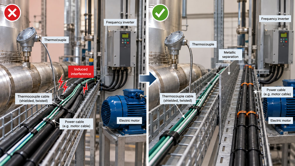
An industrial temperature measuring point indicates a constant 220 °C during normal operation. As soon as a nearby frequency inverter starts its motor, the displayed temperature begins to fluctuate between 215 and 235 °C. When the motor is switched off, the indication stabilizes again. However, the actual process temperature has hardly changed during this short period. An inspection of the thermocouple sensor itself also reveals no abnormalities.
The cause may lie in the electrical installation: the thermocouple cable runs alongside a power cable for several meters. Changing magnetic fields, high rates of voltage change and different electrical potentials can couple interference voltages into the sensitive thermocouple signal.
Unlike many industrial transmitters, thermocouples do not provide an already amplified standard signal. The temperature information is initially available as a very small thermoelectric voltage. For a type K thermocouple, the sensitivity within a limited temperature range around 200 °C is approximately 40 to 41 µV/K. An additional effective interference voltage of just 0.4 mV can therefore theoretically correspond to an apparent temperature change of approximately 10 K.
Long thermocouple cables running parallel to motor cables, inverter outputs, contactors, heater power supplies or other power-carrying cables can be particularly susceptible to interference. Several interference mechanisms must be distinguished: inductive coupling caused by time-varying magnetic fields, capacitive coupling caused by electric fields, and common-mode interference resulting from different electrical potentials.
A shielded cable can improve interference immunity, but it is not a universal solution. The decisive factors are cable construction, conductor twisting, the type of coupling, shield termination, equipotential bonding and the characteristics of the connected measuring input.
Under certain conditions, a shield connected at only one end can prevent low-frequency shield equalizing currents. With high-frequency interference, such as that generated by frequency inverters, however, a shield connection at both ends with low impedance and the largest possible contact area may be necessary. The appropriate configuration must be determined according to the specific EMC and grounding concept.
Another source of error is confusing electromagnetic interference with an actual temperature measurement error. Incorrect compensating cables, reversed thermocouple conductors, connection terminals at different temperatures or unsuitable cold junction compensation can also cause incorrect temperature readings. Such errors cannot simply be eliminated by adding a cable shield.
This technical article explains the physical causes of electromagnetic interference affecting thermocouple cables and shows how low-interference cable routing can be planned in industrial installations. The focus is on separating signal and power cables, selecting suitable thermocouple cables, applying the correct shielding and grounding strategy, and using galvanically isolated temperature transmitters.
A detailed calculation example illustrates how small coupled voltages can produce significant apparent temperature deviations. Sensor construction, heat transfer, cold junction compensation, diagnostics, commissioning and suitable products from the ICS range are also discussed.
Table of Contents
- Measurement Task and Typical Interference in Industrial Plants
- Thermoelectric Voltage and Physical Fundamentals
- Construction and Signal Path of a Thermocouple Measurement
- Distinguishing Inductive, Capacitive and Galvanic Interference
- Selecting Grounded and Insulated Thermocouple Measuring Junctions
- Routing Thermocouple and Power Cables Correctly
- Determining Cable Length, Interference Voltage and Measuring Range
- Practical Example: Calculating Induced Interference Voltage and Temperature Deviation
- Considering Sensor Position, Installation and Heat Transfer
- Distinguishing Thermocouple Wire, Extension Cable and Compensating Cable
- Shield Materials, Shield Connections and Shielding Effectiveness
- Grounding, Equipotential Bonding and Ground Loops
- Frequency Inverters, Motor Cables and PWM Interference
- Cold Junction Compensation and Connection Terminals
- Differential Measuring Inputs and Galvanic Isolation
- Installing Temperature Transmitters Close to the Measuring Point
- Measurement Filters, Sampling Rate and Signal Processing
- Evaluating Measurement Uncertainty and Systematic Errors Separately
- Electrical Safety, Explosion Protection and Standards
- Systematic Testing and Commissioning Procedure
- Typical Fault Symptoms and Targeted Diagnostics
- Suitable ICS Products and Selection Options
- Conclusion: Planning Low-Interference Thermocouple Measurements Correctly
- Frequently Asked Questions About Thermocouple Cable Installation
1. Measurement Task and Typical Interference in Industrial Plants
In industrial plants, thermocouples are frequently connected over considerable distances to temperature controllers, PLC inputs, recorders or transmitters.
While the temperature measuring point may be located on a furnace, pipeline or extruder, for example, signal processing takes place in a control cabinet.
Numerous electrical sources of interference may be present between the sensor and the control cabinet.
Typical examples include:
- Frequency inverters for motors and pumps.
- Power cables supplying electric heaters.
- Switching contactors and solenoid valves.
- Power contactors and semiconductor switches.
- Welding equipment and other devices carrying high electrical currents.
- Motor cables carrying pulse-width-modulated voltages.
- Poorly designed grounding and equipotential bonding systems.
- Multiple measurement channels with different ground potentials.
Susceptibility to interference depends strongly on how the thermocouple signal is transmitted.
In a direct thermocouple measurement, the small thermoelectric voltage is transmitted all the way to the measuring instrument. Any additional coupled voltage can influence the measurement result.
By contrast, at a measuring point equipped with a suitable temperature transmitter, the thermocouple signal is processed near the sensor and converted into an industrial output signal.
This can significantly reduce the length of the particularly sensitive raw signal path.
1.1 Typical Fault Symptoms
Electromagnetic interference can manifest itself in different ways.
Common symptoms include strongly fluctuating temperature readings, apparent temperature jumps or periodic changes associated with machine operating cycles.
An apparently constant temperature offset is also possible if high-frequency interference is rectified, superimposed or incorrectly evaluated due to insufficient sampling in the measuring input.
However, a fluctuating measured value does not automatically prove that electromagnetic interference is present.
Loose contacts, sensor breakage, mechanical changes at the measuring point or actual process fluctuations can also produce similar indications.
1.2 What Information Is Required?
Before modifying the installation, at least the thermocouple type, cable route, distance to the evaluation electronics, measuring input design and existing electrical interference sources should be known.
It should also be determined whether the interference is associated with a particular machine, switching function or rotational speed.
This information forms the basis for targeted and traceable troubleshooting.
2. Thermoelectric Voltage and Physical Fundamentals
A thermocouple consists of two conductors with different thermoelectric properties.
Due to the Seebeck effect, a thermoelectric voltage develops between the measuring junction and the reference junction. This voltage depends on the temperature distribution or, in the case of homogeneous conductor materials, on the temperatures of the relevant junctions.
The thermoelectric voltage is detected by suitable measuring electronics and converted into a temperature using the characteristic curve of the thermocouple type employed.
2.1 The Signal Is in the Millivolt Range
The thermoelectric voltage produced by industrial thermocouples is relatively small.
Sensitivity is often expressed in microvolts per kelvin and depends on temperature.
For a type K thermocouple, local sensitivity is approximately 40 µV/K in many industrially relevant temperature ranges.
However, a universally constant conversion factor for all temperatures is not permissible.
The exact relationships between temperature and thermoelectric voltage are described in IEC 60584-1.
2.2 Local Temperature Sensitivity
For a small temperature change, the following approximation can be used:
ΔU ≈ S(T) · ΔT
Where:
- ΔU is the change in thermoelectric voltage.
- S(T) is the local thermoelectric sensitivity.
- ΔT is the corresponding temperature change.
This gives approximately:
ΔT ≈ ΔU / S(T)
This relationship is particularly useful for estimating the possible significance of an additional coupled interference voltage.
2.3 Even Very Small Interference Voltages Can Be Significant
At an assumed sensitivity of 41 µV/K, an additional differential voltage of 410 µV theoretically corresponds to approximately 10 K.
This illustrates why thermocouple cables must be installed carefully in industrial environments with significant electrical activity.
An interference voltage does not need to reach several volts to significantly affect the temperature indication.
2.4 Temperature Characteristic Curve Instead of a Universal Factor
The standardized characteristic curves of the respective thermocouple type are used for accurate temperature calculations.
This is particularly important across wide temperature ranges because sensitivity depends on the temperature level.
The simplified microvolt-per-kelvin calculation in the following example is expressly used only to estimate a local deviation.
3. Construction and Signal Path of a Thermocouple Measurement
An industrial thermocouple measurement consists of more than the temperature sensor itself.
The complete measurement chain includes the measuring junction, connecting cable, possible transition points, cold junction compensation, measuring input and subsequent signal processing.
3.1 Measuring Junction
The measuring junction is the area where the two thermoelectric conductors are joined and whose temperature is intended to be measured.
Depending on the configuration, this junction may be electrically connected to the metallic outer sheath or insulated from it.
3.2 Thermocouple Cable
The cable between the thermocouple and the measuring electronics must be suitable for the respective measurement task.
In particular, it must correspond to the correct thermocouple type or use a suitable extension or compensating cable type.
The conductor insulation, mechanical properties and any shielding must also be suitable for the installation environment.
3.3 Connection and Transition Points
Additional thermoelectric effects can occur at connectors, terminals and transition points.
Unsuitable conductor materials and temperature differences between the two connection points are particularly critical.
3.4 Cold Junction Compensation
Because a thermocouple produces a temperature-dependent voltage difference, the reference junction temperature must be considered during evaluation.
Many modern measuring instruments and temperature transmitters provide internal cold junction compensation for this purpose.
Incorrect temperature measurement at the connection point can cause measurement errors even if the thermocouple cable is routed with minimal electromagnetic interference.
3.5 Signal Conditioning
The measuring input amplifies or digitizes the thermoelectric voltage and calculates the temperature using the corresponding characteristic curve.
Many industrial transmitters additionally offer functions such as sensor break detection, filtering, linearization and standardized output signals.
Important: The entire measurement chain must always be considered when evaluating electromagnetic interference. Even a high-quality thermocouple sensor can produce significant measurement deviations if an unsuitable connecting cable or poorly designed measuring input is used.
4. Distinguishing Inductive, Capacitive and Galvanic Interference
Not all electromagnetic interference enters a thermocouple measurement through the same physical mechanism.
The type of coupling is decisive when selecting suitable countermeasures.
4.1 Inductive Coupling
A time-varying electric current generates a time-varying magnetic field.
If a thermocouple cable runs through this field, a voltage may be induced in an effective conductor loop.
According to Faraday’s law of induction, the induced voltage depends on the rate of change of magnetic flux.
Uind = -dΦ/dt
This equation describes the relationship for a suitable closed loop.
The larger the effective loop area and the change in magnetic flux, the greater the potential coupled voltage.
Keeping the two thermocouple conductors close together or twisting them reduces the effective loop area and, in many cases, improves the suppression of inductive interference.
4.2 Capacitive Coupling
Parasitic electrical capacitances exist between adjacent conductors.
If the voltage on a power cable changes rapidly, interference currents can be coupled into adjacent signal cables through these capacitances.
For constant coupling capacitance, the simplified relationship is:
ik = Ck · dU/dt
Particularly high rates of voltage change can occur at the outputs of frequency inverters.
A suitable cable shield can reduce electric field coupling when properly connected.
4.3 Galvanic Interference and Potential Differences
Different electrical reference potentials between the measuring point, machine frame and evaluation device can cause additional interference.
With a grounded thermocouple, the measuring junction may be electrically connected to the metallic sensor sheath and therefore to the plant.
If the measuring input also has another ground connection, unwanted current paths or common-mode voltages can occur.
Suitable galvanic isolation and correctly designed equipotential bonding can reduce such problems.
4.4 Common-Mode and Differential Interference
Common-mode interference initially acts in a similar way on both thermocouple conductors relative to a reference potential.
Differential interference occurs directly between the two measuring input conductors.
A differential measuring input can suppress common-mode components within its specified limits.
However, an actual differential interference voltage cannot be eliminated solely through common-mode rejection.
| Interference Mechanism | Typical Cause | Effect on Measurement | Suitable Countermeasures |
|---|---|---|---|
| Inductive coupling | Time-varying currents and magnetic fields | Additional induced voltage in the measuring loop | Separate cable routing, small loop area, twisted conductors |
| Capacitive coupling | High rates of voltage change in adjacent cables | Coupled interference currents and voltages | Suitable cable shielding, separation of cable routes, low-impedance shield connection |
| Common-mode interference | Different potentials and electromagnetic coupling affecting both conductors | Exceeding the permissible common-mode range or conversion into differential interference | Differential measuring input, equipotential bonding, suitable galvanic isolation |
| Ground loop | Multiple unwanted galvanic connections between parts of the plant | Interference currents and potential-dependent measurement deviations | Review grounding and shielding concept, defined reference points, isolation according to manufacturer specifications |
| Switching transients | Contactors, solenoid valves, inverters and power electronics | Short temperature jumps or unstable indication | Proper suppression of interference at its source, corrected cable routing, suitable input filters |
| Thermoelectric connection error | Incorrect compensating cable or transition terminals at different temperatures | Systematic or temperature-dependent measurement deviation | Correct cable, correct polarity, isothermal connection conditions and cold junction compensation |
Countermeasures should always be selected according to the actual interference mechanism.
For example, additional shielding can reduce capacitive coupling but is not an equivalent substitute for a small loop area when dealing with magnetic induction.
5. Selecting Grounded and Insulated Thermocouple Measuring Junctions
The electrical design of the thermocouple measuring junction influences its behavior in the presence of electromagnetic interference and potential differences.
5.1 Grounded Measuring Junction
In a grounded thermocouple, the thermoelectric measuring junction is electrically connected to the metallic outer sheath.
If the sheath is electrically connected to a machine housing or process installation, an electrical connection between the thermocouple signal and the plant potential may also be established.
This may offer advantages in terms of heat transfer and response time but requires careful consideration of the electrical integration.
Particularly with grounded measuring junctions, the connected measuring input must be suitable for the existing potential conditions.
5.2 Insulated Measuring Junction
In an insulated measuring junction, the thermoelectric connection is electrically isolated from the metallic outer sheath.
This can reduce direct galvanic coupling between the process installation and thermocouple input.
However, an insulated measuring junction does not eliminate all electromagnetic coupling.
Capacitive coupling, insufficient shielding and unsuitable connecting cables can still cause interference.
5.3 Heat Transfer and Response Time
A grounded measuring junction can respond faster than a comparable insulated configuration because of the direct thermal contact between the measuring junction and outer sheath.
However, the actual response time depends on the complete sensor design and installation conditions.
A large thermowell diameter or unfavorable heat transfer can partially or completely offset the advantage of a particular junction construction.
5.4 Selection Based on the Complete System
The choice between grounded and insulated measuring junctions must consider mechanical requirements, required response time and the electrical interference environment.
A grounded measuring junction combined with a suitable galvanically isolated measuring input can be a technically appropriate solution.
An insulated measuring junction may offer advantages where potential differences are problematic.
Neither configuration is fundamentally superior under all conditions.
6. Routing Thermocouple and Power Cables Correctly
Cable routing is one of the most important measures for preventing electromagnetic interference.
If thermocouple cables are routed directly parallel to power cables over long distances, electrical and magnetic coupling can increase significantly.
6.1 Prefer Separate Cable Routes
Wherever possible, thermocouple cables should be routed separately from power cables.
This is particularly important for motor cables connected to frequency inverters and other cables carrying high rates of current or voltage change.
A separate cable tray or suitably partitioned metallic installation area can improve interference immunity.
6.2 Shared Cable Trays
If a shared cable tray is structurally unavoidable, it must be checked whether the cable systems used and the required separation measures are suitable for the installation.
A metallic partition can help reduce electromagnetic coupling.
For such a partition to be effective, factors including electrical contact, conductivity and the high-frequency characteristics of the separating system must be considered.
An arbitrary thin plastic partition does not provide the same electromagnetic shielding effect as a suitably designed metallic separation.
6.3 Limit Parallel Cable Runs
Long parallel cable runs increase the possibility of interference being coupled along the shared route.
Long-distance parallel routing should therefore be avoided wherever possible.
However, there is no universally applicable minimum separation distance that guarantees interference-free operation independently of cable type, shielding, power, installation and EMC environment.
Required separation distances must be determined according to the applicable installation requirements and manufacturer documentation.
6.4 Cable Crossings
If thermocouple and power cables must cross, a short crossing at approximately 90° is often preferable to a long parallel run.
This reduces the length over which the cables are coupled.
The mechanical and electrical installation requirements must also be observed in this case.
6.5 Twisting the Conductors
For suitable cable configurations, the two conductors of the thermocouple circuit should be kept as close together as possible.
A twisted pair reduces the effective area of the measuring loop and can therefore reduce magnetically induced interference in particular.
However, twisting does not replace suitable shielding or separation from strongly interfering cables.
6.6 Protective Conductors and Safe Separation
Required electrical safety must not be compromised by measures intended to improve measurement signal quality.
In particular, protective earth connections and prescribed equipotential bonding conductors must not be disconnected to eliminate an apparent ground loop.
Electrical separation and shielding must be implemented within the intended safety and EMC concept.
7. Determining Cable Length, Interference Voltage and Measuring Range
When planning a thermocouple measurement, a distinction must be made between the actual thermal measuring range and the electrical conditions of the signal path.
7.1 Selecting the Thermocouple Type
Depending on their type, thermocouples have different characteristic curves, temperature ranges and thermoelectric sensitivities.
Process temperature, operating atmosphere, required accuracy and mechanical sensor design are decisive for selection.
For example, using a type K thermocouple is not necessary merely because electromagnetic interference occurs in the plant.
7.2 Cable Length
Increasing cable length can increase cable capacitance, the potential coupling distance and installation complexity.
However, cable length alone does not automatically cause a proportional voltage drop at an ideally high-impedance thermocouple measuring input, unlike a current-carrying power cable.
In practice, conductor resistance, input bias currents, leakage currents, parasitic capacitances and poor contacts can nevertheless be relevant.
7.3 Interference Voltage Relative to the Useful Signal
The susceptibility of a temperature measurement to interference does not depend solely on the absolute magnitude of the interference voltage.
The decisive factor is how large the interference voltage is relative to the local sensitivity of the thermocouple.
At a sensitivity of approximately 41 µV/K, an additional differential voltage of just 100 µV corresponds to an apparent temperature deviation of approximately 2.4 K.
7.4 Transmitter Measuring Range
A temperature transmitter should be configured for the actually relevant temperature range.
An unnecessarily large output measuring range can adversely affect the resolution of the process indication when using downstream analog acquisition.
However, the selected measuring range must not impermissibly exclude possible actual process conditions.
7.5 Permissible Cable Temperature
The permissible cable temperature must be considered separately from the measuring range of the thermocouple.
A sensor may be suitable for high process temperatures, while the connected PVC, silicone or PTFE cable has a significantly lower permissible ambient temperature.
When designing the measurement system, the sensor and cable insulation must therefore each be selected according to their actual installation conditions.
8. Practical Example: Calculating Induced Interference Voltage and Temperature Deviation
An industrial plant uses a type K thermocouple to monitor the temperature of a heated machine.
The thermocouple sensor is connected to a temperature measuring input in the control cabinet via a relatively long cable.
For part of its route, the thermocouple cable runs parallel to the motor cable of a frequency inverter.
When the motor is operating, implausible fluctuations briefly occur in the temperature indication.
8.1 Initial Data and Assumptions
The following freely selected technical assumptions are explicitly used for this calculation example:
- Thermocouple type: type K.
- Actual process temperature: 200 °C.
- Total length of thermocouple cable: 40 m.
- Partially shared routing with a motor cable.
- Assumed local thermocouple sensitivity: 41 µV/K.
- Assumed additional differential interference voltage at a particular measurement instant: +0.410 mV.
- Temperature transmitter measuring range: 0 to 400 °C.
- Linear transmitter output signal: 4 to 20 mA.
- Cold junction compensation: assumed ideal and error-free for this example.
The cable length and coupled interference voltage are freely selected example values.
The assumed interference voltage cannot be calculated directly from the 40 m cable length. Additional information about field strengths, conductor geometry, coupling, shielding and frequency spectrum would be required.
8.2 Convert Interference Voltage into Microvolts
The assumed interference voltage is:
Uinterference = 0.410 mV
Since 1 mV equals 1,000 µV:
Uinterference = 410 µV
8.3 Calculate the Apparent Temperature Deviation
For a small temperature change, the following approximation applies:
ΔT ≈ Uinterference / S(T)
Substituting the assumed values:
ΔT ≈ 410 µV / (41 µV/K)
ΔT ≈ 10 K
In this simplified example, the coupled interference voltage can therefore cause an apparent temperature deviation of approximately +10 °C.
At an actual temperature of 200 °C, the measurement would theoretically indicate approximately 210 °C at the instant considered.
With an interference voltage of the opposite polarity, -410 µV, the indication could fall to approximately 190 °C.
This analysis describes the effect of a differential input interference voltage acting at the particular measurement instant. Pure high-frequency AC interference does not automatically produce a constant temperature offset. Actual indication behavior depends on frequency, filtering, sampling and possible rectification within the measuring input.
8.4 Output Signal of the Temperature Transmitter
For a temperature transmitter linearly configured from 0 to 400 °C with a 4-to-20-mA output, the following applies:
I = 4 mA + 16 mA · (T – Tmin) / (Tmax – Tmin)
At the actual process temperature of 200 °C:
I = 4 mA + 16 mA · 200 / 400
I = 12.00 mA
At an apparent temperature of 210 °C:
I = 4 mA + 16 mA · 210 / 400
I = 12.40 mA
The difference is:
ΔI = +0.40 mA
An interference voltage acting at the thermocouple input can therefore appear as a seemingly valid temperature change in the industrial current signal after signal conditioning.
8.5 Second Calculation Case with Lower Interference Voltage
If the effective interference voltage is reduced to an example value of 82 µV at the measurement instant through improved installation, the result is:
ΔT ≈ 82 µV / (41 µV/K)
ΔT ≈ 2 K
The same actual process temperature would therefore be indicated as approximately 202 °C with positive interference voltage.
The corresponding output signal would be:
I = 4 mA + 16 mA · 202 / 400
I = 12.08 mA
The calculated temperature deviation decreases from approximately 10 K to approximately 2 K.
The assumed reduction in interference voltage does not represent a guaranteed shielding attenuation for any particular cable or product.
| Parameter | Assumption or Calculation | Result |
|---|---|---|
| Thermocouple type | Type K | Type K |
| Actual process temperature | Freely selected example value | 200 °C |
| Thermocouple cable | Freely selected length | 40 m |
| Local sensitivity | Simplified assumption | 41 µV/K |
| Interference voltage before assumed improvement | Freely selected example value | 410 µV |
| Apparent temperature deviation | 410 µV / 41 µV/K | +10 K |
| Calculated temperature indication | 200 °C + 10 °C | 210 °C |
| Current signal without interference | 4 mA + 16 mA · 200 / 400 | 12.00 mA |
| Current signal with assumed interference | 4 mA + 16 mA · 210 / 400 | 12.40 mA |
| Reduced interference voltage in the second calculation case | Freely selected comparison value | 82 µV |
| Remaining apparent temperature deviation | 82 µV / 41 µV/K | +2 K |
| Current signal in the second calculation case | 4 mA + 16 mA · 202 / 400 | 12.08 mA |
8.6 Technical Interpretation
The calculation example demonstrates that relatively small differential interference voltages at the thermocouple input can cause clearly visible temperature deviations.
It is particularly important to understand that a temperature transmitter does not necessarily recognize a thermoelectric voltage already distorted at the measuring input as an error.
If the interference voltage remains within the plausible measuring range, it can produce an apparently valid temperature value.
A correctly functioning 4-to-20-mA output can subsequently transmit this incorrect temperature value in full compliance with the applicable signal standard.
The sensitive raw thermocouple signal path should therefore be designed to minimize interference as far as possible.
8.7 Limitations of the Calculation
The sensitivity of 41 µV/K used in the example is a local approximation.
The exact conversion must be based on the characteristic curve of the actual thermocouple type.
Furthermore, the additional interference voltage was assumed to act directly as a differential input voltage.
Real electromagnetic interference may be frequency-dependent and may affect the temperature indication differently due to common-mode rejection, input filtering, sampling or nonlinear effects.
The calculation is therefore an estimate of the possible order of magnitude, not a universal prediction model for every thermocouple installation.
9. Considering Sensor Position, Installation and Heat Transfer
An implausible temperature reading is not necessarily caused by electromagnetic coupling.
The mechanical installation conditions and heat transfer between the process medium and sensor can also cause significant measurement deviations.
9.1 Insertion Length and Measuring Position
A thermocouple measures the temperature at its thermally effective measuring junction.
If the measuring junction is not inserted sufficiently deeply into the process medium, heat may be conducted away through the sensor sheath and process connection.
The indicated value may then lie between the actual process temperature and the temperature of the surroundings or connection fitting.
9.2 Thermal Contact
For thermocouples installed in thermowells, heat transfer between the thermowell and measuring insert is decisive.
Insufficient contact can increase response time and cause additional measurement deviations.
In suitable designs, spring-loaded measuring inserts can improve thermal contact with the bottom of the thermowell.
9.3 Response Time
A rapid temperature change in the process may be indicated with a delay due to thermal inertia.
This effect must be distinguished from electromagnetic interference.
While electrical interference may occur almost immediately when a motor is switched on, a genuine thermal change follows the physical heat transfer conditions of the process.
9.4 Contact and Surface Measurement
A thermocouple mounted on the surface of a pipeline initially measures the local surface temperature.
This is not necessarily identical to the temperature of the flowing medium.
The pipe wall, insulation, contact pressure and possible heat loss must be considered when evaluating the measurement.
9.5 Distinguishing Electrical and Thermal Errors
A useful diagnostic approach first determines whether the unusual indication is temporally associated with electrical switching operations or with actual changes in the thermal process.
Comparison with a suitable independent reference temperature measurement can be helpful.
10. Distinguishing Thermocouple Wire, Extension Cable and Compensating Cable
In addition to electromagnetic compatibility, the thermocouple cable must also have suitable thermoelectric properties for the measurement task.
Ordinary copper cable is not automatically a suitable replacement for thermocouple extension cable.
10.1 Thermocouple Wire
Thermocouple wire consists of the thermoelectric conductor materials intended for the respective thermocouple.
Its specific suitability depends on the temperature range, accuracy requirements, mechanical construction and insulation.
10.2 Extension Cable
Extension cables have thermoelectric properties suitable for the respective thermocouple type within the specified range.
The designation typically includes the corresponding thermocouple letter followed by X.
For example, KX identifies an extension cable for type K thermocouples.
10.3 Compensating Cable
Compensating cables may consist of alloys different from the actual thermocouple conductors.
Their thermoelectric properties are matched to the respective thermocouple within a specified temperature range.
The designation typically uses the thermocouple type letter followed by C.
Additional variations are identified for certain types of compensating cables.
10.4 Observe Temperature Limits
Extension and compensating cables cannot be used without restriction across all process temperatures.
The permissible conductor and insulation temperatures and the specified thermoelectric tolerances must be observed.
Particularly with long cables running alongside heated equipment, sections of the cable route may be exposed to elevated temperatures.
10.5 Polarity
The positive and negative thermocouple conductors must be connected correctly.
Reversed polarity can cause significant incorrect readings.
Conductor identification must be checked against the standard applicable to the cable and the manufacturer’s data sheet.
Color coding may differ between international identification systems.
10.6 IEC 60584-3
IEC 60584-3 describes requirements for extension and compensating cables, including their tolerances and identification.
The selection of a shielded thermocouple cable should therefore not be based solely on its shielding performance.
The correct thermoelectric conductor pairing must also be verified.
11. Shield Materials, Shield Connections and Shielding Effectiveness
A cable shield is intended to reduce electromagnetic coupling.
However, its effectiveness depends on the frequency range, cable construction and, in particular, correct termination.
11.1 Foil Shield
A foil shield can provide high coverage of the cable conductors and is frequently suitable for reducing electric field coupling.
The intended termination method and mechanical characteristics must be considered during installation.
11.2 Braided Shield
A metallic braided shield can offer good electrical termination options and, depending on its construction, can be mechanically robust.
At high frequencies, shield impedance and the method of shield connection play an important role.
11.3 Combined Shields
Depending on the application, cables with combined foil and braided shields may be used.
The suitable configuration depends on the expected interference spectrum and installation conditions.
11.4 Shield Connection
An existing shield is only as effective as its actual electrical connection allows.
Particularly with high-frequency interference, long, thin shield connection wires can significantly reduce shielding effectiveness due to their inductance.
A large-area, low-impedance termination, for example using suitable EMC cable glands or shield clamps, can therefore be beneficial.
11.5 Connection at One End or Both Ends?
Whether a shield should be connected at one end or both ends depends on the intended grounding concept and the relevant interference frequencies.
Connecting at one end can help prevent low-frequency shield equalizing currents.
For high-frequency interference, a low-impedance connection at both ends may be technically preferable, provided suitable equipotential bonding is available.
The manufacturer’s instructions for the sensor, transmitter, inverter and control cabinet installation must be considered.
11.6 A Shield Is Not a Protective Earth Conductor
The shielding of a thermocouple cable must not be used as a substitute for a required protective earth conductor without appropriate design and verification.
Protective earth and equipotential bonding perform safety-related functions that must be maintained independently of any optimization of the measurement signal.
12. Grounding, Equipotential Bonding and Ground Loops
Different grounding and reference potentials are a frequent cause of unexpected signal interference in industrial temperature measurements.
12.1 Electrical Connection of the Measuring Junction
With a grounded thermocouple, the measuring junction may be electrically connected to the sensor sheath.
The sensor sheath may in turn be electrically connected to the process plant.
This can create an electrical connection between the thermocouple input and a remote plant potential.
12.2 Second Reference Point at the Measuring Instrument
If the thermocouple input also has a galvanic reference to the control cabinet potential, unwanted potential differences may become effective.
Whether this results in interference depends on the actual input circuit and existing electrical connections.
12.3 Equipotential Bonding
Properly implemented equipotential bonding reduces unwanted potential differences between conductive plant components.
For high-frequency interference, connection impedance and geometric routing must also be considered.
An electrically conductive connection with low DC resistance does not automatically have equally low impedance at high frequencies.
12.4 Galvanic Isolation
A galvanically isolated temperature transmitter can interrupt the direct electrical connection between the thermocouple input and downstream output circuit.
This can be particularly useful with grounded thermocouples and different plant potentials.
However, the specified isolation data and permissible input conditions of the device must still be observed.
12.5 No Unauthorized Changes to Protective Earth Connections
An apparent grounding problem must not be solved by disconnecting required protective earth connections.
Likewise, safety-related equipotential bonding connections must not be removed solely to improve a temperature indication.
Such measures can create serious electrical hazards.
13. Frequency Inverters, Motor Cables and PWM Interference
Frequency inverters are among the most relevant sources of interference in industrial temperature measurement systems.
When driving a motor, the inverter typically generates pulsed output voltages.
13.1 High Rate of Voltage Change
The switching edges of a pulse-width-modulated voltage can have very high rates of voltage change.
Through parasitic capacitances, these can couple interference currents into adjacent cables and conductive plant components.
Long parallel routing of motor and thermocouple cables can increase this coupling.
13.2 Varying Motor Currents
Motor cables carry time-varying currents.
The resulting magnetic fields can induce voltages in adjacent conductor loops.
Twisted thermocouple conductors with a small loop area can reduce this inductive coupling.
13.3 Frequency Dependence
The interference that occurs is not necessarily limited to the 50 Hz mains frequency.
Switching operations in power electronics can also produce relevant frequency components at significantly higher frequencies.
A filter designed solely for 50 Hz is therefore not sufficient for every type of inverter interference.
13.4 Shielded Motor Cables
Proper installation of the motor cable also influences the electromagnetic environment.
Motor cables, shield connections, EMC cable glands and equipotential bonding measures specified by the manufacturer must be implemented according to the inverter installation concept.
A poorly connected motor cable shield can significantly worsen interference conditions in adjacent measurement cables.
13.5 No Arbitrary Filters at the Inverter Output
Measures intended to reduce interference on the motor cable must be coordinated with the inverter manufacturer and the intended plant design.
Additional filters or changes to the output circuitry must not be made without technical verification.
13.6 Diagnostics Through Time-Based Comparison
A temperature disturbance that begins immediately when an inverter is switched on and disappears when it is switched off is a strong indication of an electrical relationship.
However, actual thermal process changes and other possible influences must still be ruled out for definitive confirmation.
14. Cold Junction Compensation and Connection Terminals
A thermocouple produces a thermoelectric voltage whose interpretation requires a known or measured reference temperature.
Cold junction compensation is therefore an essential part of temperature measurement.
14.1 Location of the Reference Junction
For a directly connected thermocouple, the relevant reference junction is often located at the measuring input or its connection area.
The measuring input requires suitable temperature measurement at that location.
14.2 Temperature Gradients at Connection Terminals
If the two connection terminals are at different temperatures, the evaluation can be affected.
Connection areas heated unevenly by adjacent power components, fans or other heat sources are particularly unfavorable.
A connection environment with the most uniform possible temperature is therefore important.
14.3 Unsuitable Transition Conductors
If thermocouple and copper conductors are joined without considering the resulting transition junctions, additional errors can occur.
The effect depends on the conductor pairings and temperatures at the respective transitions.
Suitable thermocouple connectors and terminals can help maintain controlled thermoelectric conditions.
14.4 Cold Junction Compensation in a Head-Mounted Transmitter
When a temperature transmitter is installed in the connection head, cold junction compensation is located close to the sensor.
This can reduce the length of the unfiltered raw thermocouple signal path.
However, the connection head must not be exposed to arbitrarily high temperatures or large temperature gradients.
14.5 Interference or Reference Junction Error?
A slowly drifting deviation may, for example, depend on temperature changes inside the terminal box.
By contrast, a measured value jump that occurs immediately when an inverter switches may indicate electromagnetic coupling.
Both causes can occur simultaneously and must be investigated separately if necessary.
15. Differential Measuring Inputs and Galvanic Isolation
The connected measuring input has a major influence on how effectively a thermocouple measurement suppresses electromagnetic interference.
15.1 Differential Voltage Measurement
A suitable differential measuring input measures the voltage difference between the two thermocouple conductors.
As a result, interference voltages acting in the same way on both conductors can be suppressed within the specified limits.
This characteristic is known as common-mode rejection.
15.2 Common-Mode Rejection Ratio
Common-mode rejection can be described by the Common-Mode Rejection Ratio, abbreviated CMRR.
A high CMRR value can be advantageous for interference immunity.
However, the actual effect is frequency-dependent and only applies within the permissible electrical input conditions.
15.3 Limitations of Common-Mode Rejection
A differential input cannot readily suppress an interference voltage already present between the two thermocouple conductors.
Asymmetrical cable impedances or capacitive coupling can also convert common-mode interference into differential interference.
Symmetrical cable construction, twisting and suitable cable routing therefore remain important.
15.4 Galvanically Isolated Inputs
Galvanic isolation can reduce unwanted DC connections between the measuring point and evaluation electronics.
It is particularly useful when relevant potential differences exist between plant sections or when grounded thermocouples are used.
However, galvanic isolation is not a substitute for EMC-compliant wiring.
15.5 Input Protection
Suitable measuring inputs may include protective circuits against certain electrical overload conditions.
Such protection functions must be appropriate for the application with regard to permissible common-mode voltage, overvoltage and measurement accuracy.
The actual permissible input conditions are specified in the respective manufacturer documentation.
16. Installing Temperature Transmitters Close to the Measuring Point
One particularly effective measure may be to process the sensitive thermocouple signal close to the sensor.
Temperature transmitters for installation in connection heads or suitable field enclosures are available for this purpose.
16.1 Short Raw Signal Path
With a head-mounted transmitter, the thermocouple is connected directly or through a suitable short connection.
This reduces the length over which the small thermoelectric voltage is exposed to electromagnetic interference.
16.2 Transmission as a 4-to-20-mA Signal
A temperature transmitter can convert the measured temperature into a standardized current signal.
A correctly designed 4-to-20-mA signal path often offers advantages over direct thermoelectric voltage transmission across longer distances.
However, a low-interference installation is still necessary for current signals.
16.3 Galvanic Isolation
A temperature transmitter with galvanic isolation can reduce electrical coupling between the thermocouple input and output current circuit.
This can mitigate a possible source of interference caused by different potentials.
The specific isolation function and its limits must be stated in the data sheet.
16.4 Digital Diagnostics
Depending on the device, functions such as sensor break detection, measuring range monitoring and diagnostic messages may be available.
For devices with HART communication, additional parameters and diagnostic information may be accessible through the intended interface.
16.5 Correct Temperature Transmitter Position
A transmitter should be installed as close as possible to the measuring point without exceeding its permissible ambient temperature or other operating limits.
If the connection head is very hot, separate mounting in a cooler area may be necessary.
In that case, the thermocouple connecting cable up to the transmitter remains part of the sensitive signal path.
16.6 Measurement Errors Before the Transmitter
A temperature transmitter cannot automatically correct a thermoelectric voltage that has already been distorted.
Electrical interference directly between the measuring junction and transmitter input can therefore still appear as an apparent temperature change after conversion into a 4-to-20-mA signal.
The direct sensor connection must consequently also be installed correctly.
17. Measurement Filters, Sampling Rate and Signal Processing
In addition to electromagnetic installation conditions, signal processing influences the behavior of coupled interference.
17.1 Mains Frequency Rejection
Many thermocouple measuring inputs offer filter options for typical mains frequencies such as 50 Hz and 60 Hz.
These can reduce low-frequency interference.
Effectiveness depends on the particular circuit, selected filter and interference frequency.
17.2 High-Frequency Interference
Pulse-width-modulated inverter signals can contain higher-frequency interference components.
A filter designed exclusively for 50 Hz may not sufficiently reduce such interference.
Corresponding filter concepts must be matched to the characteristics of the measuring input.
17.3 Measurement Damping
Digital or analog measurement damping can stabilize the indication.
However, it can also delay the indication of actual rapid temperature changes.
Damping should therefore not be set so high that important thermal process changes are concealed.
17.4 Sampling and Aliasing
If high-frequency interference voltages are not adequately filtered, they can appear as apparently slowly changing measurement components during digitization.
This behavior is known as aliasing.
Suitable analog bandwidth limiting before digitization is therefore an important part of the measuring electronics.
17.5 Slow Temperature Change or Electrical Jump?
The thermal response time of the sensor can help distinguish between these effects.
If the indication changes significantly within a very short period, even though the actual measuring point has substantially greater thermal inertia, electrical interference should be investigated as a possible cause.
This is a diagnostic indication, not definitive proof.
18. Evaluating Measurement Uncertainty and Systematic Errors Separately
The measurement uncertainty of a thermocouple measurement is determined by several components.
A high sensor accuracy class alone does not guarantee a correspondingly small deviation for the complete temperature measuring point.
18.1 Thermocouple Tolerance
The thermocouple type and its tolerance class determine the permissible thermoelectric deviations under the specified conditions.
The tolerances for the corresponding thermocouples are defined in IEC 60584-1.
18.2 Cable Tolerance
Extension and compensating cables have their own tolerances and permissible temperature ranges.
An unsuitable or incorrectly assigned cable can cause additional systematic measurement errors.
18.3 Cold Junction Compensation
An error in measuring the connection junction temperature affects the calculated process temperature.
The actual effect depends on the thermocouple characteristic curve and the temperatures involved.
18.4 Measuring Input
Resolution, measurement error, temperature drift and common-mode rejection of the measuring input influence the overall result.
At low input voltages, even small electrical offset effects can be significant.
18.5 Electromagnetic Interference
A coupled interference voltage can cause periodic fluctuations, unstable indications or apparent offsets under certain conditions.
It must be evaluated according to the actual interference conditions.
Unknown electromagnetic interference must not simply be replaced by an arbitrarily selected constant uncertainty contribution.
18.6 Heat Transfer and Installation
Heat conduction along the sensor, insufficient insertion length or poor contact with the measuring point can cause errors considerably larger than the inherent sensor tolerance.
These systematic effects must be investigated separately.
18.7 Overall Evaluation
For a reliable measurement uncertainty assessment, the relevant contributions must be identified and evaluated using a suitable model.
Possible correlations and nonlinear relationships must be taken into account.
Simply adding all data sheet errors does not automatically constitute a complete measurement uncertainty budget.
19. Electrical Safety, Explosion Protection and Standards
Improving electromagnetic compatibility must not compromise the electrical safety of the plant.
19.1 Protective Earth Connections
Required protective earth connections must be installed and maintained according to applicable electrical safety regulations.
Unwanted measurement fluctuations are not a permissible reason to remove a protective earth conductor.
19.2 Equipotential Bonding
Equipotential bonding connections must be implemented according to the electrical installation concept.
Both low-frequency and high-frequency characteristics are relevant to EMC-compliant installation.
19.3 Electromagnetic Compatibility
IEC 61326-1 specifies general EMC requirements for electrical equipment for measurement, control and laboratory use.
Additional or specific standards apply to certain equipment types.
However, compliance with an EMC equipment standard does not automatically guarantee interference-free operation in every possible installation where power and signal cables are routed together.
19.4 Thermocouple Standards
IEC 60584-1 contains the thermoelectric voltage characteristic curves and tolerances for the corresponding thermocouple types.
IEC 60584-3 specifies requirements for extension and compensating cables, including tolerances and identification.
These standards are particularly relevant when selecting thermocouple signal cables.
19.5 Hazardous Areas
For thermocouple measuring points in hazardous areas, the applicable types of explosion protection, equipment approvals and installation conditions must be considered.
For intrinsically safe circuits in particular, the permissible electrical parameters and associated wiring are decisive.
Changes to shield or grounding connections must not be made without checking the relevant explosion protection requirements.
19.6 Functional Safety
A temperature measurement can form part of a safety-related protective function.
In such applications, the measuring instrument, sensor, signal processing and complete safety function must be evaluated separately.
Using an interference-resistant temperature transmitter alone does not automatically mean that the complete temperature monitoring system is approved for a particular safety requirement.
20. Systematic Testing and Commissioning Procedure
A structured approach should be used when installing or troubleshooting thermocouple cables.
The following steps are intended for metrological testing and assume that all work is carried out according to the approved electrical safety procedure.
- Define the measurement task: Specify the thermocouple type, temperature range, required accuracy and permissible measurement fluctuations.
- Identify the sensor: Document the thermocouple type, construction and grounded or insulated measuring junction.
- Check the cable type: Ensure that the thermocouple wire, extension cable or compensating cable matches the sensor.
- Verify polarity: Check the positive and negative thermocouple conductors using the applicable identification.
- Document the cable route: Record length, cable routing, feedthroughs and any sections shared with power cables.
- Identify interference sources: Consider frequency inverters, motor cables, heating controls and other relevant electrical consumers.
- Evaluate cable separation: Check whether separate cable routes or suitable metallic partitions are present.
- Check conductor twisting: Determine whether the thermocouple conductors are suitably routed as a pair.
- Check shield construction: Document cable shielding, continuity and intended shield connection points.
- Verify shield termination: Compare the installation with the approved grounding and EMC concept.
- Check equipotential bonding: Properly examine existing electrical reference potentials and equipotential bonding connections.
- Check the measuring input: Verify thermocouple type, input circuitry, cold junction compensation and possible galvanic isolation.
- Document filter settings: Check mains frequency rejection, measurement damping and sampling rate.
- Perform a functional test: Check the measurement chain using a suitable thermocouple or mV reference.
- Rule out reference junction errors: Investigate connection terminals, temperature gradients and cold junction compensation.
- Verify process measurement plausibility: Compare the indication with a suitable independent reference measurement.
- Assign interference events in time: Compare measurement changes with approved machine operating and switching states.
- Define corrective measures: If interference is confirmed, adjust cable routing, shielding, input configuration or transmitter location.
- Recheck the measuring function: After modifications, verify the temperature measurement and relevant operating conditions.
- Complete the documentation: Record cable routing, shielding concept, device parameters, test results and corrective measures in a traceable manner.
Modifications must not impair protective earth connections, explosion protection requirements or other safety-related functions.
21. Typical Fault Symptoms and Targeted Diagnostics
When thermocouple readings are unstable, the cause should be narrowed down by examining the actual signal behavior.
The following table shows typical observations and possible diagnostic approaches.
| Fault Symptom | Possible Cause | Suitable Diagnostic Action |
|---|---|---|
| Temperature indication fluctuates when a motor is switched on | Inductive or capacitive coupling | Investigate cable route, motor cable, shielding and timing of the event |
| Measured value changes with inverter speed | Frequency-dependent coupling or changed actual process conditions | Compare interference frequencies, inverter operation and an independent temperature reference |
| Indication jumps when a contactor switches | Electrical switching transients or potential interference | Check the interference source, wiring and input filters |
| Temperature indication has a permanent offset | Incorrect compensating cable, cold junction error, thermal installation error or electrical interference | Check cable type, reference junction and measurement chain using a suitable reference |
| Measured value changes when the terminal box heats up | Incorrect cold junction compensation or thermoelectric transition junctions | Investigate temperature distribution at terminals and CJC function |
| Indication responds in the wrong direction | Reversed thermocouple polarity or unsuitable wiring | Verify polarity and thermocouple type |
| Measured value fluctuates only with a grounded thermocouple | Potential differences or common-mode problems | Check electrical measuring junction coupling and suitability of the measuring input |
| Shielding provides little improvement | Magnetic coupling, insufficient shield termination or another interference mechanism | Investigate conductor twisting, cable separation and type of interference coupling |
| Temperature indication is heavily damped | Large filter time constant or thermally slow sensor | Check measurement filters and thermal sensor response time separately |
| Temperature value deviates at high process temperatures | Insufficient insertion length, heat conduction or unsuitable cable temperature rating | Evaluate installation conditions, heat transfer and permissible cable temperature |
| Measurement becomes more stable after transmitter installation | Shorter raw signal path, improved signal conditioning or galvanic isolation | Compare old and new signal paths, including filters and grounding |
The listed causes are possible diagnostic explanations and do not constitute definitive fault identification.
Several causes may occur simultaneously. Electrical and thermal error sources in particular should be investigated separately before replacing measuring instruments or sensors.
22. Suitable ICS Products and Selection Options
ICS Schneider Messtechnik offers thermocouples, temperature transmitters and accessories for a wide range of industrial temperature measurement tasks.
For a low-interference installation, the sensor itself is not the only important component. The correct connecting cable, electrical measuring junction construction and signal conditioning are equally decisive.
22.1 WIKA TC40 – Cable Thermocouple
The WIKA TC40 is a cable thermocouple for industrial temperature measurements in machinery, motors, bearings, pipelines and vessels.
It is designed for applications where the metallic sensor tip can be inserted directly into suitable bores or process measuring points.
Documented features include:
- Sensor ranges from -40 to +1,200 °C, depending on configuration.
- Insertion versions or versions with an optional threaded process connection.
- Different connecting cables with PVC, silicone, PTFE or glass fiber insulation.
- Mechanically robust industrial sensor construction.
- Availability of corresponding explosion-protected versions.
The TC40 can be used, for example, where a temperature measuring point is located near electrical machinery or drives.
The specific cable configuration must be selected according to temperature, thermocouple type and electromagnetic environment.
Existing cable shielding, cable length and electrical measuring junction configuration must be checked for the actual ordered version.
The general TC40 product description does not provide a blanket guarantee that every configuration already includes a particular shielding construction.
Further Information: WIKA TC40 at ICS Schneider Messtechnik
22.2 WIKA TC10-B – Industrial Thermocouple for Installation in a Thermowell
The WIKA TC10-B is an industrial thermocouple with a thermowell configuration for suitable process measuring points.
It is particularly relevant for applications in mechanical and plant engineering, as well as the energy and process industries.
Documented features include:
- Sensor ranges up to +1,200 °C in suitable configurations.
- Industrial thermowell construction.
- Replaceable, spring-loaded measuring inserts.
- Configurable sensor and connection versions.
- Availability of corresponding explosion-protected variants.
For a measuring point with demanding thermal and electromagnetic conditions, the sensor design, electrical isolation of the measuring junction, connection head and intended signal conditioning are particularly relevant.
When a suitable temperature transmitter is used, the sensitive thermocouple signal can be processed directly in the connection head.
Whether a particular transmitter can be installed directly must be checked against the specific mechanical and electrical configuration.
The thermowell, insertion length and heat transfer must also be suitable for the process application.
Further Information: WIKA TC10-B at ICS Schneider Messtechnik
22.3 WIKA T32.xS – Digital Temperature Transmitter with HART
The WIKA T32.xS is a digital temperature transmitter for industrial process applications.
Among other sensor types, it supports the connection of thermocouples and resistance thermometers.
Documented features include:
- Universal input for different sensor types, including thermocouples.
- Versions for head and rail mounting.
- Digitally configurable measuring ranges.
- 4-to-20-mA output with HART communication.
- Galvanic isolation.
- Sensor break detection and fault signaling.
- EMC characteristics according to the applicable manufacturer specifications.
- Configuration-dependent versions for safety applications.
The T32.xS is particularly interesting where low-interference signal conditioning is required close to the thermocouple measuring point.
By converting the signal into an industrial current signal, the sensitive thermocouple voltage cable can be limited to a short section.
Galvanic isolation can also help reduce unwanted potential coupling between the sensor and downstream evaluation electronics.
The actual permissible input conditions, degree of protection and transmitter version must match the specific application.
Further Information: WIKA T32.xS at ICS Schneider Messtechnik
22.4 Siemens SITRANS TH320 – Temperature Transmitter
The Siemens SITRANS TH320 is a temperature transmitter designed for installation in a connection head.
The device supports different sensor types and is suitable for industrial temperature measurement tasks in mechanical engineering and process automation.
Documented features include:
- Universally configurable input for thermocouples and other suitable sensors.
- Compact design for installation in a type B connection head.
- Galvanically isolated two-wire output.
- 4-to-20-mA output with HART communication.
- Wire break and input signal monitoring.
- Diagnostic LED and internal diagnostic functions.
- Configuration-dependent functional safety options.
- Documented EMC characteristics according to relevant manufacturer specifications and standards.
The SITRANS TH320 is a potential solution where the thermocouple signal is to be processed near the sensor and transmitted over an industrial current loop.
Integrated galvanic isolation can be particularly advantageous where different electrical reference potentials are present.
For correct selection, the specific thermocouple configuration, transmitter ambient temperature and electrical installation requirements must be considered.
Even with this transmitter, the thermocouple cable between the measuring junction and input must be installed correctly.
Further Information: Siemens SITRANS TH320 at ICS Schneider Messtechnik
22.5 ICS Thermocouples – Various Sensor Designs
The ICS Thermocouples range includes different configurations of industrial thermocouples.
These include, among others:
- Thermocouples with connection heads.
- Mineral-insulated thermocouples.
- Thermocouple measuring inserts.
- Special designs for different industrial requirements.
- Suitable explosion-protected versions.
- Precision thermocouples.
When selecting a low-interference measuring point, the electrical sensor design, thermocouple type, mounting method and intended connecting cable are particularly relevant.
For special installation conditions, adapted sensor and cable routing can help shorten the sensitive signal path.
The exact configuration must be determined according to the specific technical requirements.
Further Information: ICS Thermocouples
22.6 ICS Components and Accessories – Connection Technology
The ICS Components and Accessories range offers various components for industrial temperature measuring points.
The product range includes connection heads, thermocouple elements, connectors, mounting fittings, thermowells and other components for constructing complete temperature measurement chains.
Suitable connectors and connection components are particularly important when joining thermocouple cables.
The connection materials and their thermoelectric properties must be compatible with the thermocouple type used.
For shielded cables, the intended shield feedthrough or shield termination must also be compatible with the complete installation.
However, using a suitable connector does not replace correct cable routing or proper cold junction compensation.
Further Information: ICS Components and Accessories
22.7 Selecting a Complete Thermocouple Measurement Chain
The following information should be available for reliable device and cable selection:
- Thermocouple type and temperature range.
- Required sensor construction and electrical isolation of the measuring junction.
- Installation conditions, including thermowell and heat transfer.
- Distance between sensor and evaluation device.
- Existing power cables and interference sources along the cable route.
- Possible sections shared with frequency inverter motor cables.
- Required cable construction, particularly twisting and shielding.
- Existing grounding and equipotential bonding concept.
- Permissible cable temperatures.
- Required output signals and communication interfaces.
- Required accuracy and measurement uncertainty.
- Any required explosion protection or safety approvals.
- Requirements for calibration, testing and documentation.
Based on this information, it can be determined whether a direct thermocouple cable is suitable or whether local signal conditioning using a temperature transmitter would be preferable.
Temperature Measurement Technology at ICS Schneider Messtechnik
23. Conclusion: Planning Low-Interference Thermocouple Measurements Correctly
Thermocouples are suitable for numerous demanding temperature measurement tasks in industrial plants.
However, their very small thermoelectric input voltages require careful electrical installation.
Particularly when thermocouple cables are routed together with motor and power cables, electromagnetic interference can occur and significantly distort the temperature indication.
The most important finding is that different interference mechanisms require different countermeasures.
Inductive coupling is influenced in particular by time-varying magnetic fields and the effective loop area of the measuring circuit.
Capacitive coupling is caused by electric fields and parasitic capacitances between adjacent cables.
Additional errors can arise from potential differences and unfavorable galvanic connections between the sensor, plant and measuring electronics.
A shielded cable alone therefore does not automatically solve every problem.
For low-interference measurement, thermocouple cables should be routed separately from strongly interfering power cables wherever possible.
Twisted conductor pairs with a small effective loop area can reduce inductive interference. Suitable shields and properly installed connections can limit capacitive and high-frequency coupling.
The method of shield connection must be compatible with the EMC and equipotential bonding concept.
The often-quoted general rule that shielding should only be grounded at one end is not correct under all conditions. A different termination strategy may be necessary, particularly for high-frequency inverter interference.
Another effective measure may be to use a suitable temperature transmitter close to the measuring point.
This converts the sensitive thermoelectric voltage into an industrial output signal at an early stage. Galvanic isolation, where available, can additionally reduce unwanted potential coupling.
At the same time, correct thermocouple installation must not be neglected.
Incorrect extension cables, reversed polarity, unsuitable connection terminals or cold junction compensation errors can cause measurement deviations unrelated to electromagnetic induction.
Sensor position, insertion length, heat transfer and thermal inertia must also be considered for reliable temperature measurement.
Systematic troubleshooting should therefore examine the complete measurement chain, from the thermocouple itself through the connecting cable to the evaluation device.
The key conclusion is: Routing thermocouple and power cables together is not simply a cable issue. Only a coordinated combination of suitable cable routing, twisting, shielding, grounding, signal conditioning and correct thermocouple installation enables permanently reliable temperature measurements.
24. Frequently Asked Questions About Thermocouple Cable Installation
24.1 Can Thermocouple Cables Be Routed Together with Power Cables?
Shared cable routing should be avoided wherever possible, particularly with power cables that generate significant interference. Whether it is permissible and technically suitable in a specific installation depends on the applicable installation requirements, electrical safety, cable construction and electromagnetic conditions. Separate cable routes or suitable metallic partitions may be required.
24.2 Why Are Thermocouples Sensitive to Electromagnetic Interference?
Thermocouples produce very small voltages, often in the microvolt or millivolt range. Even an additional differential voltage of a few hundred microvolts can therefore cause a significant apparent temperature deviation. Particularly long and poorly routed measuring cables may be exposed to electromagnetic coupling.
24.3 How Are Interference Voltages Induced in Thermocouple Cables?
Time-varying electric currents generate changing magnetic fields. If these fields pass through an effective measuring conductor loop, voltages can be induced. Their magnitude depends, among other factors, on the rate of change of magnetic flux and cable geometry. Keeping the conductors close together and twisting them appropriately can reduce the effective loop area.
24.4 Does a Shielded Thermocouple Cable Protect Against All Interference?
No. A suitable cable shield can reduce electric field coupling and certain high-frequency interference in particular. However, ordinary shielding is not automatically equally effective against low-frequency magnetic coupling. Suitable cable routing, small loop areas and correct electrical integration are therefore also necessary.
24.5 Must the Shield of a Thermocouple Cable Be Grounded at One End Only?
Not necessarily. A connection at one end can be useful under certain low-frequency potential conditions. For high-frequency electromagnetic interference, a low-impedance shield connection at both ends can be advantageous, provided suitable equipotential bonding is available. The manufacturer’s specifications and the specific EMC and grounding concept of the plant are decisive.
24.6 What Distance Is Required Between Thermocouple and Motor Cables?
A universally applicable minimum separation distance cannot be specified independently of operating conditions. Required distances depend, among other factors, on motor power, switching frequencies, cable shielding, routing, metallic partitions and applicable installation requirements. Long parallel cable runs should generally be avoided wherever possible.
24.7 Why Should Thermocouple Conductors Be Twisted?
Twisting keeps both conductors close together over long distances. This can reduce the effective area of the measuring loop, allowing time-varying magnetic fields to induce less differential interference voltage. Twisting is an important measure but does not replace other EMC-compliant installation practices.
24.8 Can Frequency Inverters Distort Thermocouple Measurements?
Yes. Frequency inverters generate pulsed output voltages and time-varying motor currents. These can couple into adjacent thermocouple cables through electric and magnetic fields. Long parallel cable routes and unsuitable shield connections are particularly critical. Proper EMC installation of both the motor cable and measuring cable can improve interference immunity.
24.9 Can an Induced Voltage of 0.4 mV Already Cause a Significant Temperature Error?
Yes. For a type K thermocouple with an assumed local sensitivity of approximately 41 µV/K, 0.41 mV theoretically corresponds to about 10 K. However, the effect of a real interference voltage on the indication also depends on its frequency characteristics, filtering and signal processing. High-frequency AC interference does not necessarily produce a constant offset.
24.10 Is a Grounded Thermocouple More Susceptible to Interference Than an Insulated One?
A grounded thermocouple can establish a galvanic connection between the measuring signal and process installation. This may increase susceptibility to interference where different potentials are present. An insulated thermocouple reduces this direct coupling but is not automatically immune to electromagnetic interference. Suitability depends on the complete measurement chain.
24.11 Why Does the Temperature Indication Fluctuate When a Motor Is Switched On?
One possible cause is electromagnetic coupling from the motor cable or associated power electronics. Changes in ground potentials or switching transients may also be relevant. Diagnosis should examine the timing relative to motor operation, cable route, shielding and an independent temperature reference.
24.12 What Is the Difference Between Thermocouple Wire and Compensating Cable?
Thermocouple wire consists of suitable thermoelectric conductor materials for the respective thermocouple type. Compensating cable may use different alloys whose thermoelectric properties are matched within a defined temperature range. Correct selection and identification are important because unsuitable cables can cause systematic temperature measurement errors.
24.13 Can a Thermocouple Cable Be Extended Using Ordinary Copper Cable?
Ordinary copper cable is not automatically suitable for extending a thermocouple. The additional junctions and their temperatures can influence the measurement. Suitable thermocouple extension or compensating cables are normally used. Copper cable is appropriate only after suitable signal conversion or within a measuring arrangement expressly designed for such use.
24.14 Can a Temperature Transmitter Prevent Electromagnetic Interference?
A suitable temperature transmitter can reduce susceptibility to interference because the small thermoelectric voltage is processed near the measuring point and converted into a more robust output signal. Galvanic isolation can additionally mitigate potential-related problems. However, interference coupled into the thermocouple signal before the transmitter input can still cause measurement errors.
24.15 What Are the Advantages of a Galvanically Isolated Temperature Transmitter?
Galvanic isolation can interrupt unwanted direct electrical connections between the thermocouple input and downstream output circuit. This can reduce problems caused by different electrical reference potentials. The isolation must be suitable for the actual operating conditions and does not replace correct shielding, cable routing or electrical protective measures.
24.16 Why Does the Thermocouple Show an Incorrect Value When the Terminal Box Heats Up?
One possible cause is cold junction compensation. If the relevant connection points are at different temperatures or their temperature is not measured correctly, the calculated process temperature may deviate. Unsuitable connection materials or additional thermoelectric junctions can also play a role. The thermal conditions inside the terminal box should therefore be examined.
24.17 How Do You Check a Thermocouple Measurement for Electromagnetic Interference?
First, the thermocouple type, cable, polarity and cold junction compensation should be checked. Next, determine whether the measurement deviation is associated with particular electrical operating conditions. Suitable reference measurements and proper inspection of cable routing, shielding and the measuring input can help identify the cause. All work must comply with electrical safety requirements.
24.18 When Is It Advisable to Route Thermocouple Cables Completely Separately from Power Cables?
Separate cable routing is particularly advisable for long cable runs, frequency inverters, high motor currents or applications with demanding measurement accuracy requirements. It reduces the possibility of electromagnetic coupling and makes a traceable EMC-compliant installation easier to achieve. The required separation must be determined according to the electrical installation, manufacturer specifications and applicable installation requirements.