


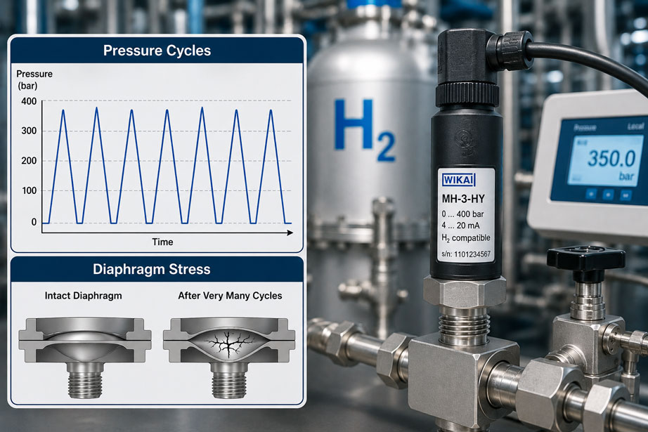
A hydrogen pressure sensor has a measuring range of 0 ... 400 bar and is used in an application in which the pressure regularly cycles between 30 bar and 350 bar. The maximum operating pressure is therefore well within the measuring range. Nevertheless, in a test bench, a hydrogen refueling station or a cyclically operated fuel-cell system, an additional question arises: What effect does this load have if it occurs not only a few hundred times, but hundreds of thousands or millions of times?
The maximum pressure alone is not sufficient for this assessment. The metallic measuring diaphragm of a pressure sensor is elastically deformed with every pressure increase and returns to its original position whenever the pressure is relieved. If this process is repeated very frequently, cyclic mechanical loading occurs. How critical this is depends, among other things, on pressure amplitude, mean pressure, number of load cycles, diaphragm geometry, material and temperature.
Hydrogen introduces an additional influencing factor. Hydrogen can penetrate certain metallic materials and influence their properties. In pressure sensors, thin metallic separating diaphragms are particularly relevant. Hydrogen permeation can affect measurement behavior over the long term, while an unsuitable combination of materials can increase susceptibility to embrittlement and crack formation.
For dynamic hydrogen pressure measurement, the question should therefore not only be: “What is the maximum pressure?”, but also: “Between which pressure levels does the system cycle, how often does this happen and is the specific measuring cell suitable for hydrogen and this cyclic load?”
Why must frequent pressure cycles be assessed differently from constant pressure?
Under static pressure, the measuring diaphragm is loaded and remains largely in a constant mechanical condition. In a cyclic process, by contrast, it is continuously deformed and unloaded again. Each pressure cycle therefore creates a load cycle within the metallic component.
Simply remaining below the permissible maximum pressure does not fully describe how the measuring cell will behave under a very high number of such load cycles. A sensor may, for example, operate for years at an almost constant 300 bar in a storage application, while an identical device on a component test bench experiences millions of pressure cycles within a short period. Although the same maximum pressure may occur in both applications, the mechanical loading is significantly different.
| Operating condition | Load on the measuring diaphragm | Particularly relevant |
|---|---|---|
| Largely constant pressure | Predominantly static loading | Maximum pressure, temperature, hydrogen compatibility |
| Slow regular pressure cycles | Cyclic deformation | Pressure amplitude and number of load cycles |
| Fast pressure pulsations | Many load cycles within a short time | Dynamics, frequency and diaphragm loading |
| Additional pressure peaks | High short-term stress | Overload capability and actual peak pressure |
What does fatigue of the measuring diaphragm mean?
Metallic components can fatigue as a result of repeated mechanical loading. The decisive factor is not only whether an individual load condition remains below the immediate failure limit. A very high number of recurring stress variations can lead to material changes over time and, under unfavorable conditions, promote crack formation.
In a pressure measuring cell, this particularly affects the thin sections of the diaphragm that are intentionally designed to deform elastically. They must be flexible enough to detect the process pressure while at the same time remaining mechanically stable throughout the intended service life. Diaphragm thickness, geometry, material, joining points and the actual pressure load therefore form a complete system.
No universal permissible number of cycles can be derived from the normal measuring range alone. If an application requires, for example, a verified service life of several million full-load or partial-load cycles, this requirement should already be specified during device selection and confirmed for the specific sensor version with the manufacturer.
Why is pressure amplitude decisive?
For cyclic loading, not only the highest pressure is important, but also the difference between the minimum and maximum pressure of each cycle. A sensor that continuously cycles between 290 bar and 310 bar experiences a different cyclic load from a sensor that regularly cycles between 10 bar and 310 bar, even though both have the same maximum pressure.
For the specification of such a measuring point, at least the minimum pressure, maximum pressure and expected number of pressure cycles should therefore be known. In fast test benches, cycle frequency and rate of pressure increase must also be considered. Individual unplanned overpressure events should be assessed separately as well.
| Process parameter | Example | Meaning |
|---|---|---|
| Minimum pressure | 30 bar |
Lower load point of the cycle |
| Maximum pressure | 350 bar |
Upper load point |
| Pressure amplitude | 320 bar between minimum and maximum |
Measure of the magnitude of the recurring pressure cycle |
| Cycle frequency | e.g. 1 Hz |
Determines how quickly a high number of cycles accumulates |
| Planned number of cycles | e.g. several million | Important service-life requirement for the measuring point |
A test bench operating at one cycle per second already reaches approximately 3.6 million load cycles within 1,000 operating hours. A seemingly moderate test duration can therefore correspond mechanically to a very high number of pressure load events.
What additional influence does hydrogen have?
Hydrogen places additional demands on metallic measuring cells. Due to its very small molecular size and the interaction of atomic hydrogen with metallic materials, hydrogen can penetrate materials. Depending on the material, pressure, temperature and exposure time, permeation and hydrogen embrittlement can become relevant.
In a pressure sensor, hydrogen permeation through a thin separating diaphragm can influence the long-term stability of the measuring system. At the same time, the material of the pressure-bearing and elastically loaded components must be selected so that its properties are maintained under the intended hydrogen operating conditions. Particularly where many load cycles occur, hydrogen compatibility and mechanical fatigue should therefore not be considered completely independently of one another.
The extent to which these effects occur depends strongly on the specific measuring-cell design. For this reason, the general statement “stainless steel is resistant to hydrogen” is too simplistic for qualified sensor selection. Alloy, material condition, diaphragm thickness, coating, joining process and actual pressure conditions are decisive.
What role do diaphragm material and coating play?
Manufacturers of hydrogen-compatible pressure sensors use different design strategies. One option is to use particularly suitable alloys offering high resistance to hydrogen effects and high mechanical fatigue strength. The WIKA MH-3-HY, for example, uses a metallic thin-film measuring cell with a special material suitable for hydrogen.
Another strategy is to reduce permeation through the metallic separating diaphragm by means of an additional barrier coating. The Druck UNIK5000H uses a separating diaphragm specially optimized for hydrogen with a barrier coating and hydrogen-compatible wetted components. This is intended in particular to reduce the long-term influence of hydrogen on the measuring cell.
Which solution is more suitable depends on the application. A vehicle, electrolyzer, laboratory test bench and 700-bar refueling station place different demands on pressure range, accuracy, temperature, electrical interfaces, size and required service life.
Distinguishing measuring range, overpressure and fatigue strength
Three specifications are frequently confused in dynamic applications: measuring range, overpressure capability and permissible cyclic loading. The measuring range describes the range within which the sensor is intended to provide its specified measurement performance. The overpressure capability describes a higher pressure that the device can withstand without immediate damage under the conditions specified by the manufacturer.
However, an overpressure capability of, for example, twice the measuring range does not automatically mean that this pressure may be applied millions of times as a normal operating point. An overload specification is therefore not a substitute for evaluating cyclic service life. Particularly in highly dynamic hydrogen test benches, the specified load-spectrum requirement should be matched to the specific sensor version.
| Specification | What it describes | What does not automatically follow from it |
|---|---|---|
| Measuring range | Specified range of pressure measurement | No statement about an unlimited number of full-range cycles |
| Overpressure capability | Permissible short-term pressure load according to the manufacturer’s specification | No automatic permanent approval for operation at this pressure |
| Burst pressure | Pressure limit relating to structural failure | Not a normal operating range |
| Cyclic service life | Behavior under repeated pressure loading | Must be assessed for the specific load profile |
Taking the frequency and speed of pressure cycles into account
In addition to pressure amplitude, the time behavior can also be relevant. A slow pressure cycle every ten minutes differs from a test bench that cycles between two pressure levels several times per second. At high frequencies, not only does the total number of cycles increase very quickly, but the requirements placed on the dynamic measuring capability of the sensor and downstream data acquisition also increase.
The measuring chain must be sufficiently fast if not only the maximum and minimum pressure but also the actual pressure profile over time is to be investigated. A sensor with limited bandwidth or a heavily filtered PLC can overlook fast pressure peaks even though they still reach the diaphragm mechanically.
In addition, fast valve switching or very short filling operations can generate pressure peaks that are significantly higher than the expected steady-state pressure. For service-life assessment, the actual pressure profile should therefore be investigated wherever possible instead of relying only on the setpoint and nominal system pressure.
Practical example: cyclic hydrogen test bench
On a component test bench, hydrogen pressure is repeatedly increased from 30 bar to 350 bar and then reduced again. The pressure sensor used has a measuring range of 0 ... 400 bar. Based purely on the measuring range, the selection initially appears reasonable.
However, the test bench performs one complete load cycle per second. After 1,000 operating hours, the measuring diaphragm has therefore experienced approximately 3.6 million pressure cycles. In addition, short pressure peaks occur when the valves switch, which are barely visible in the slower test-bench data recording.
For a reliable assessment, the information “maximum 350 bar hydrogen” is therefore not sufficient. Device selection must additionally consider that a very large pressure amplitude is repeated millions of times. The material and measuring-cell design must also be suitable for permanent contact with hydrogen.
If the measuring point is later replaced with a sensor that also measures up to 400 bar but was selected only for general hydraulic media, the identical pressure-range specification cannot be regarded as proof of equal suitability for the hydrogen test bench.
The load profile therefore belongs to the specification of the pressure measuring point just as much as the measuring range, medium and temperature.
How can developing changes be detected?
Mechanical changes or changes influenced by hydrogen in a measuring cell do not necessarily appear immediately as a complete sensor failure. An early indication may be increasing zero-point shift, altered repeatability or a gradually increasing deviation from a reference.
For test benches exposed to strong cyclic loading, regular comparison testing can therefore be useful. If the zero point and several pressure points are checked at defined intervals against a sufficiently accurate reference, trends can be identified before the measuring point clearly fails.
Leak tightness should also be monitored. With hydrogen, even a small change in a sealing point or pressure-bearing component can be relevant due to the gas’s high tendency to diffuse. Noticeable drift, unusual dynamic behavior or detectable leakage should therefore not simply be compensated for by a new zero adjustment.
Systematically selecting a hydrogen pressure sensor
- Clearly specify the medium: State hydrogen concentration, gas quality and any possible accompanying substances.
- Define minimum and maximum operating pressure: Do not specify only the nominal system pressure.
- Determine the pressure amplitude of the normal load cycle.
- Estimate the expected number of load cycles over the planned service life.
- Take cycle frequency and the rate of pressure increase and decrease into account.
- Investigate additional pressure surges and exceptional operating conditions.
- Select a measuring-cell and material version explicitly suitable for hydrogen.
- For high required cycle counts, confirm suitability for the specific load profile with the manufacturer.
- Assess measuring range, overpressure capability and required measurement dynamics separately.
- For critical test benches, provide for regular comparison or calibration checks.
Common mistakes
- Specifying only the maximum pressure: In strongly cyclic applications, this omits pressure amplitude and number of cycles as essential design parameters.
- Confusing overpressure capability with fatigue strength: A sensor must not be exposed to an overpressure value millions of times solely because this value appears in its overload specification.
- Automatically using a conventional stainless-steel sensor for hydrogen: Suitability depends on the specific material and measuring-cell design.
- Failing to detect pressure peaks: Slow PLC recording can miss short but mechanically relevant peaks.
- Documenting only operating hours: On a cyclic test bench, the number of pressure cycles is often more informative.
- Simply readjusting zero-point drift: Increasing drift can indicate changes in the measuring cell and should first be investigated.
- Selecting the sensor solely by measuring range: Hydrogen compatibility, temperature, dynamics, connections and load profile must also be taken into account.
Pressure sensors for hydrogen applications
For dynamic hydrogen applications, a pressure sensor should be used whose wetted measuring cell is explicitly designed for hydrogen. One specific example is the WIKA MH-3-HY. The compact OEM pressure sensor is designed for hydrogen pressure measurement and is particularly suitable for fuel-cell and mobile H₂ applications. Its measuring-cell design uses a metallic material suitable for hydrogen with high fatigue strength.
For industrial test benches, hydrogen production, pipeline networks or refueling stations, the Druck UNIK5000H is another solution specifically designed for hydrogen. It is available with measuring ranges from 700 mbar to 700 bar. Hydrogen-compatible wetted materials and an optimized barrier coating on the separating diaphragm reduce the influence of hydrogen permeation.
However, whether a particular version is suitable for a cyclic application cannot be determined from the product name or measuring range alone. If a service life of several million pressure cycles is specified, minimum pressure, maximum pressure, temperature, frequency and expected total number of cycles should already be stated in the inquiry.
Suitable components can be found under H² hydrogen applications at ICS Schneider and specifically under H² pressure sensors. Further information is available for the WIKA MH-3-HY and the Druck UNIK5000H.
Conclusion
For hydrogen pressure measurement with a very high number of load cycles, it is not sufficient to select a sensor solely on the basis of maximum process pressure. Every pressure cycle deforms the measuring diaphragm again. With hundreds of thousands or millions of cycles, the mechanical fatigue strength of the measuring cell therefore becomes an important selection criterion.
The maximum pressure is not the only decisive factor. Minimum pressure, pressure amplitude, cycle frequency, actual number of cycles and additional pressure peaks also determine the load. Measuring range and overpressure capability do not replace an assessment of the cyclic load profile.
Hydrogen adds further requirements. Depending on the material and measuring-cell design, permeation and hydrogen embrittlement can affect long-term stability. Pressure sensors developed specifically for hydrogen and equipped with suitable diaphragm materials or barrier coatings should therefore be used.
For a reliable H₂ pressure measuring point, the following therefore applies: consider hydrogen compatibility and pressure-cycle resistance together, specify the actual load profile rather than only the maximum pressure, and for high required cycle counts verify the specific measuring-cell design including material, overload limits and expected service life.
FAQ: Hydrogen pressure measurement with many load cycles
Why are many pressure cycles relevant for a pressure sensor?
With every pressure cycle, the measuring diaphragm is mechanically deformed and unloaded again. With a very high number of such load cycles, fatigue loading of the metallic measuring system can become relevant.
Is it sufficient if the maximum pressure is within the measuring range?
No. For highly cyclic applications, minimum pressure, pressure amplitude, number of load cycles, cycle frequency and possible pressure peaks must also be considered.
Is overpressure capability the same as pressure-cycle resistance?
No. Overpressure capability describes a permissible pressure load under the conditions specified by the manufacturer. It cannot automatically be assumed that this pressure may be applied cyclically an unlimited number of times.
Why is hydrogen particularly demanding for the measuring diaphragm?
Hydrogen can penetrate certain metallic materials. As a result, effects such as permeation and hydrogen embrittlement can become relevant. Thin metallic separating diaphragms in pressure sensors therefore require an appropriately suitable material and design.
Which information should be specified for a cyclic hydrogen test bench?
Important information includes hydrogen quality, minimum pressure, maximum pressure, expected pressure peaks, temperature, cycle frequency, pressure rise time and the planned total number of pressure cycles.
Can a 0…400-bar sensor automatically withstand millions of cycles between 0 and 350 bar?
This cannot be determined from the measuring range alone. A required high number of cycles should be assessed based on the specific measuring cell and the actual load profile.
Which signs may indicate a change in the measuring cell?
Possible indications include increasing zero-point drift, altered repeatability, deviations from a reference or unusual dynamic measurement behavior. Such changes should be investigated rather than simply adjusted out.
Which specific pressure sensor is suitable for hydrogen?
One example is the WIKA MH-3-HY, which was developed specifically for hydrogen pressure measurement. For industrial hydrogen applications, the Druck UNIK5000H is also available with hydrogen-compatible materials and an optimized barrier coating on the separating diaphragm.
Why should the number of cycles be documented on test benches?
A test bench can generate several million load cycles within a relatively short operating time. The number of operating hours alone therefore provides only an incomplete description of the mechanical loading of the measuring diaphragm.
How can the service life of a hydrogen pressure sensor be increased?
Key factors are a measuring-cell design suitable for hydrogen, a pressure range matched to the actual load profile, avoidance of unnecessary pressure peaks and device selection that already takes the planned number of load cycles into account.