


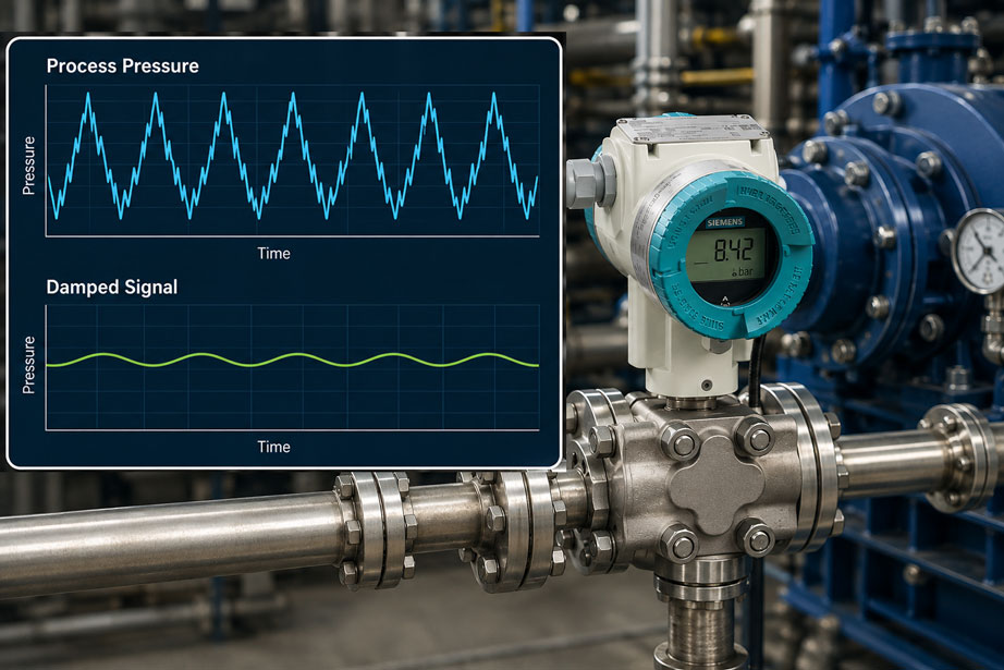
A SITRANS P320 measures the pressure downstream of a pump. Without additional damping, the displayed value fluctuates continuously, for example between 7.6 bar and 9.2 bar. After increasing the electronic damping, the signal suddenly appears almost stable at around 8.4 bar. Does this mean that the pressure pulsation in the process has also been eliminated?
No. Electronic damping changes the time response of the measurement signal. Rapid changes are smoothed and therefore appear less pronounced on the display or at the 4–20 mA output. However, the actual pressure wave in the pipeline remains unchanged. If the pump generates real pressure peaks of, for example, 12 bar, this load still acts on the process connection and measuring cell – even if the damped output signal only shows a considerably lower and smoother trend.
This distinction is particularly important with reciprocating pumps, metering pumps, compressors, fast-switching valves and other dynamic processes. Strong electronic damping can be useful for process control, but at the same time it can smooth relevant pressure peaks in the transmitted signal so strongly that their mechanical significance is underestimated.
The damping function of the SITRANS P320 is therefore a signal-conditioning tool and not a means of mechanically protecting the pressure transmitter. Signal stability, process dynamics and permissible pressure loading must be assessed separately.
Why does process pressure pulsate?
Many industrial processes do not generate perfectly constant pressure. With a piston or diaphragm pump, for example, the medium is not conveyed continuously but in individual delivery strokes. This creates periodic pressure changes. Rapidly opening or closing valves, compressors, hydraulic units and changing consumers can also generate dynamic pressure fluctuations.
A pulsation should be distinguished from an individual very fast pressure peak or pressure surge. A pulsation typically repeats regularly at the machine or pump frequency. A pressure surge, on the other hand, can be caused by a valve closing abruptly and may be considerably shorter in duration. Both phenomena can be relevant to the measuring point, but they place different demands on measurement speed and mechanical load capability.
| Pressure behavior | Typical cause | Effect on the measurement |
|---|---|---|
| Slow pressure change | Process control, level or load change | Can also be measured reliably with moderate damping |
| Regular pulsation | Reciprocating pump, metering pump, compressor | Display and 4–20 mA signal may fluctuate considerably |
| Short pressure peak | Rapid valve switching, pressure surge | May appear strongly attenuated in the output signal due to electronic damping |
| Mechanical overload | Peak above the permissible sensor load | Measuring cell can be stressed or damaged despite a smooth output signal |
What does the electronic damping of the SITRANS P320 do?
The SITRANS P320 features configurable electronic damping. It is used to smooth rapid changes in the process value within the output signal. On the HART version, the damping value can be set within a range of 0.01 s to 100 s. A larger time constant produces a smoother signal, but at the same time increases the transmitter’s response time to real pressure changes.
The principle can be compared with a low-pass filter. Slow changes pass through largely unchanged, while rapid changes are attenuated. If the process pressure changes from 8 to 10 bar within a very short period, for example, a strongly damped output signal follows this step only with a delay.
This function is useful when rapid pressure fluctuations are not relevant to the actual process control and only a stable indication or smooth control value is required. However, it should not be used simply to make unknown process problems visually disappear.
Why do real pressure peaks not disappear?
Electronic damping takes place only within the transmitter’s signal processing. Before that, the process pressure has already acted mechanically on the separating diaphragm or measuring cell. The electronics can therefore prevent a fast pressure peak from appearing fully at the 4–20 mA output, but they cannot prevent the peak from reaching the sensor.
Assume that the normal process pressure is approximately 8 bar and that a pulsating pump generates very short peaks up to 13 bar. With strong damping, the transmitted signal may only fluctuate between 8.0 and 8.6 bar. It must not be concluded from this that the process itself also reaches only 8.6 bar.
For mechanical sizing, the highest pressure actually occurring in the process must therefore be considered. The configured measuring range of the output signal or the visible display is not sufficient for this purpose.
Balancing damping and response time correctly
Higher damping improves signal stability but at the same time reduces the time resolution of the measurement. For slow pressure control, this may be uncritical or even desirable. For fast control, leak detection or monitoring of dynamic pressure events, however, excessive damping can delay important information.
| Damping | Signal behavior | Typical application |
|---|---|---|
| Very low | Fast response, pulsations clearly visible | Analysis of dynamic processes, fast control |
| Moderate | Good compromise between response and signal stability | General process pressure measurement |
| High | Very stable indication, fast events strongly smoothed | Slow processes with disturbing pulsation |
| Too high for the application | Relevant process changes appear with a delay | Can impair control and diagnostics |
The ideal setting therefore does not result from the desire for the smoothest possible indication. The decisive factor is how quickly the process actually needs to be monitored or controlled.
How can pressure peaks disappear from the measurement signal?
Very short pressure peaks can be attenuated at several points in a measuring chain. In addition to the electronic damping of the transmitter, the internal response time of the measuring cell, the sampling rate of a PLC, filters in the analog input and the update cycle of the process visualization all influence the visible dynamics.
A pressure surge lasting only a few milliseconds can therefore be mechanically present even though it is not clearly visible either on the local display or in the normal trend chart of a PLC. If the actual peak value is to be investigated, the entire measuring chain must be sufficiently fast. A fast reference measurement or high-speed data acquisition may therefore be required for targeted analysis.
The location of the measurement also plays a role. Pressure waves can propagate through pipelines and be reflected at restrictions, valves or closed ends. A transmitter at another position can therefore detect different dynamic pressure behavior from the point at which the critical component is actually loaded.
Selecting measuring range and overload capability correctly
In a pulsating process, the measuring range should not be derived solely from the average operating pressure. Expected pulsation peaks, exceptional operating conditions, start-up, shutdown and possible faults must also be considered.
The measuring range and permissible overload must be distinguished from one another. The configured 4–20 mA range defines which pressure is assigned to which output signal. The permissible mechanical load on the measuring cell, on the other hand, is a design characteristic of the specific device version.
The available P320 measuring cells have different limit and overload values depending on the pressure range. A transmitter configured for 0 ... 10 bar, for example, must therefore not automatically be assumed to tolerate arbitrarily high short-term pressure peaks. The specific Siemens version, including measuring cell and permissible process loading, must be considered when selecting the device.
When is mechanical pulsation damping useful?
If rapid pressure fluctuations not only disturb the signal but also place significant mechanical stress on the measuring point, purely electronic damping may not be sufficient. In this case, hydraulic or pneumatic damping upstream of the sensor can be useful. Depending on the medium and application, possible solutions include restrictors, pulsation dampers, appropriately dimensioned impulse lines or specially designed pressure surge dampers.
Unlike electronic filtering, such a measure actually changes the pressure transmission to the measuring cell. It must therefore be designed carefully. Excessive throttling can significantly delay the measurement signal, lines can become blocked and unsuitable damping elements can cause additional problems with viscous or contaminated media.
Before using mechanical damping, it should therefore be clarified whether the pulsation is merely disturbing the indication or whether relevant pressure peaks or high cyclic loading of the measuring cell are actually present.
Systematically diagnosing a pulsating measuring point
- First document the damping: Check which damping value is currently configured in the SITRANS P320.
- Observe the process with the lowest practical damping: This reveals which dynamics the transmitter is actually detecting.
- Determine the frequency and magnitude of the pulsation: Distinguish regular pump pulsation from individual pressure surges.
- Check the measuring range and permissible load of the specific P320 measuring cell.
- Consider the entire measuring chain: PLC filters, sampling rate and trend recording can produce additional smoothing.
- If very short peaks are suspected, use a sufficiently fast reference measurement.
- Only then set the damping so that signal stability and the required response speed are properly balanced.
- If the pulsations are mechanically critical, consider suitable process-side damping or modification of the system.
Practical example: pump with strongly fluctuating pressure signal
A SITRANS P320 monitors the discharge pressure downstream of a reciprocating pump. With low electronic damping, the signal continuously fluctuates between approximately 7.8 bar and 9.4 bar. This rapid fluctuation is disturbing for the higher-level control system because only the average discharge pressure is required.
The damping value is increased. The process control system then shows a much smoother trend around approximately 8.6 bar. The measuring point now works much better for control purposes. At the same time, however, the question arises as to whether the previously visible peaks have actually disappeared.
A fast comparison measurement directly on the pressure line shows that the mechanical pulsation is still present. Individual short peaks even reach values above those visible in the normal PLC trend. The electronic damping has therefore done exactly what it is intended to do: smooth the transmitted signal. The loading of the pipeline and measuring cell, however, has not changed.
This example shows why a smooth trend should never be used as proof that dynamic pressure peaks are no longer present.
Setting the SITRANS P320 damping value appropriately
On the HART version of the SITRANS P320, damping can be set using the parameter Damping value [04]. The range extends from 0.01 s to 100 s. A larger value results in stronger smoothing and correspondingly slower response to pressure changes.
During commissioning, it is advisable not to set a very high value immediately. First, the actual process behavior should be observed with low damping. The time constant can then be increased step by step until the signal is sufficiently stable without losing the dynamics required for control and diagnostics.
| Observation after adjustment | Assessment | Possible action |
|---|---|---|
| Signal still unnecessarily unstable | Damping may be too low | Increase damping value gradually |
| Display is stable and control is stable | Damping is probably appropriate | Document the setting |
| Real process change appears with a significant delay | Damping may be too high | Reduce damping value |
| Strong pressure peaks visible with low damping | Possible real process problem | Investigate mechanical loading and process cause |
Common mistakes
- Confusing damping with mechanical pressure reduction: Filtering changes the output signal, not the applied process pressure.
- Increasing damping without investigating the cause of the pulsation: A smooth value can merely make a real plant problem less visible.
- Equating measuring range with overload capability: The mechanical limits depend on the specific measuring cell.
- Using only the PLC trend for peak-value analysis: Sampling rate and additional filters can hide very short pressure events.
- Setting damping unnecessarily high: Relevant pressure changes and faults are then detected later.
- Using a mechanical pulsation damper as a general solution: A restrictor can change the dynamic response and may become blocked with unsuitable media.
- Specifying only normal operating pressure: Sensor selection must also take start-up, shutdown, pulsation and possible pressure surges into account.
SITRANS P320 for dynamic pressure measurements
The Siemens SITRANS P320 is a digital process pressure transmitter for gauge pressure, absolute pressure and differential pressure as well as process measurements based on these variables. For conventional pressure measurement, the 7MF0300 gauge-pressure series is available, among others. Depending on the version, different measuring ranges, process connections, materials, housing variants and approvals can be selected.
For a pulsating pressure application, selection of the correct measuring cell is particularly important. Normal operating pressure, the actually required measuring range and possible dynamic peaks should already be considered when selecting the device. The configurable electronic damping can then be used to adapt the output signal to the required process dynamics.
On the 4–20 mA/HART version, the P320 offers adjustable damping from 0.01 ... 100 s. Operation can be carried out locally on the device or via digital communication. Extensive diagnostic functions are also available.
Suitable Siemens pressure measurement technology can be found under Siemens process instrumentation at ICS Schneider. Further information on the device used here can be found under SITRANS P320 process transmitter.
Conclusion
The electronic damping of the SITRANS P320 is an effective tool for stabilizing a pulsating pressure signal for display, PLC and process control. On the HART version, the damping value can be adjusted over a wide range and therefore adapted to the dynamics of the respective application.
However, stronger damping only reduces the visible or transmitted dynamics. The actual pressure pulsation in the process line remains present. Even very short peaks can continue to act on the measuring diaphragm and process connection even if they are barely visible in the damped 4–20 mA signal.
Electronic signal filtering and mechanical sensor loading must therefore be considered separately. For selection of the P320, the maximum process pressure, possible pressure peaks and the permissible load limits of the specific measuring cell are decisive. For parameterization, on the other hand, the required response speed for control and diagnostics is the key factor.
For a robust pressure measuring point, the following therefore applies: first understand the actual process dynamics, then select the measuring range and load capability appropriately, and only afterwards set the electronic damping so that disturbing pulsations are smoothed without hiding relevant process changes.
FAQ: SITRANS P320 with pulsating process pressure
What does electronic damping do on the SITRANS P320?
Electronic damping smooths rapid changes in the measured pressure signal. This makes the display and output signal more stable, while at the same time causing the transmitter to respond more slowly to real pressure changes.
What damping range does the SITRANS P320 provide?
On the 4–20 mA/HART version, the damping value can be adjusted from 0.01 to 100 seconds. The appropriate setting depends on the required signal stability and response time.
Does electronic damping reduce real pressure peaks?
No. The pressure peak continues to act mechanically on the process connection and measuring cell. Only its representation in the output signal is attenuated by the filtering.
Can a pressure peak be present even if it is not visible in the PLC trend?
Yes. Electronic damping, the PLC sampling rate, analog input filters and the update rate of the visualization can strongly attenuate or completely hide short pressure peaks.
Why should the damping not simply be set to the maximum?
Very high damping produces a stable signal, but at the same time delays the response to real process changes. This can impair control, alarming and troubleshooting.
Does high damping protect the measuring cell against overload?
No. It does not provide mechanical protection. The actual pressure occurring in the process and the permissible load limits of the specific device version are decisive for the measuring cell.
When should a mechanical pulsation damper be used?
A mechanical or hydraulic damping element can be useful if pulsations actually place mechanical stress on the measuring point or are too severe for the required measurement. The design and damping effect must be suitable for the medium and required response time.
How do you find a suitable damping value?
The process behavior should first be observed with low damping. The value can then be increased step by step until the desired signal stability is achieved without delaying important process changes excessively.
Which SITRANS P320 is suitable for a normal gauge-pressure measurement?
A typical example is the SITRANS P320 gauge-pressure series 7MF0300 with 4–20 mA/HART. Measuring range, process connection, material and approvals must be selected to match the specific application.
What should be checked first in strongly pulsating pump applications?
First, determine how high the actual pressure peaks are and how quickly they occur. Then check the measuring range and load capability of the measuring cell. Only afterwards should it be decided whether electronic signal smoothing is sufficient or whether additional process-side damping is required.