


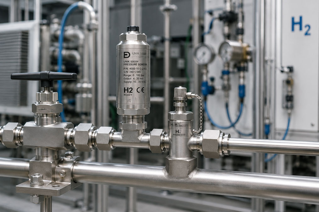
A pressure sensor is installed on a hydrogen line, the thread is firmly tightened and no external defect is visible. Nevertheless, the pressure slowly drops during the leak test or a sensitive leak detector responds directly at the measuring point. Is the sensor leaking, is the adapter incorrectly sealed or is the effect simply caused by permeation?
Especially with H₂ measuring points, simply tightening a fitting by feel is not sufficient. What matters is which thread is actually being used, where the intended sealing surface is located, which sealing principle is specified by the manufacturer and whether all adapters, seals and materials are suitable for hydrogen, pressure and temperature.
It is also necessary to distinguish between a localised leak, a measurable overall leak rate of the system and gas transport through sealing materials. A pressure drop alone therefore does not clearly indicate where a leak is located.
Components for hydrogen applications can be found under H² hydrogen applications. Special test and service connections are grouped under H² MINIMESS couplings.
Table of Contents
- Why are H₂ measuring points particularly demanding?
- Consider threads and sealing principles separately
- Do not confuse NPT and G threads
- When are metallic seals appropriate?
- Selecting the correct sealant
- Why are adapter chains problematic?
- Correctly assessing tightening torque and installation
- What does leak rate mean?
- Leak testing by pressure decay
- Helium and hydrogen leak testing
- Leakage or permeation?
- Purging, depressurisation and venting
- Typical fault patterns
- Recommended test procedure
- Practical example from an H₂ test bench
- Documenting the leak test
- Which products and solutions are suitable?
- Conclusion
- Frequently asked questions
Why are H₂ measuring points particularly demanding?
An industrial pressure measuring point often consists of more than just a sensor and pipework. In practice, shut-off valves, reducers, transition adapters, test connections, hoses and additional components are often included.
Each additional interface creates another potential leak point. Combinations in which different thread systems or sealing principles are connected are particularly critical.
With hydrogen, even very small leak paths can be relevant. A connection that appears unproblematic during normal operation with a less demanding medium should therefore not automatically be considered suitable for H₂.
For a measuring point to be leak-tight, at least five aspects must therefore be correct:
- materials of the wetted components,
- thread or connection geometry,
- sealing principle and sealing material,
- correct installation, and
- an appropriate leak test.
Consider threads and sealing principles separately
A common mistake is to assess whether a connection should be leak-tight solely from the thread designation.
The primary purpose of the thread is to mechanically connect components. Whether sealing additionally takes place at the thread flanks, an end face, a cone, an O-ring or a metallic seal depends on the specific connection design.
With a parallel connection, for example, the thread itself can be completely intact while gas still escapes if the intended sealing washer is missing or the sealing surface is damaged.
Conversely, with a tapered pipe thread, an adapter that appears to be completely screwed in can still leak if the mating geometry, engagement depth or specified thread sealant is incorrect.
Before installation, two questions must therefore always be answered:
Which thread is being used – and at which geometric location is the connection actually intended to seal?
Do not confuse NPT and G threads
NPT and G threads are among the most common connections used on pressure sensors and adapters. Although, for example, 1/4″ connections may initially appear similar, they have different geometries and sealing concepts.
| Characteristic | NPT | G thread / BSPP |
|---|---|---|
| Basic geometry | Tapered pipe thread | Parallel cylindrical thread |
| Typical sealing principle | Sealing in the area of the thread flanks using an appropriate sealing concept | Sealing normally via a separate sealing surface or sealing element |
| Installation | Observe engagement depth and specified thread sealing method | Thread mainly provides preload for the actual seal |
| Typical error | Unsuitable sealant or damaged thread flanks | Missing, incorrect or damaged seal |
With a G connection, it should therefore not automatically be assumed that the connection can be sealed by simply tightening the thread further. If, for example, a flat gasket, O-ring or metallic sealing surface is specified, exactly this element must be correctly designed and installed.
Likewise, NPT and G threads must not be screwed directly together simply because the components can initially be engaged by a few thread turns. The thread profile, pitch and geometry are not designed for such a combination.
When are metallic seals appropriate?
Metallic sealing concepts are often used in demanding gas and high-pressure applications. These include defined cone connections, metallic sealing edges or specifically designed metallic sealing rings.
The advantage is that no gas-permeable elastomer layer has to bridge the actual sealing gap. However, a metallic seal only works reliably if the intended sealing surfaces match geometrically and are in perfect condition.
Scratches, scoring, particles or incorrectly aligned fittings can immediately create a leak path.
In addition, “metal-to-metal sealing” does not automatically mean “reusable indefinitely”. Depending on the design, a sealing ring may undergo plastic deformation during installation and may subsequently need to be replaced.
The manufacturer’s specifications for the specific connection are therefore always decisive.
Selecting the correct sealant
For threads that require an additional thread sealant, an arbitrary sealing tape or sealing compound available on site must not simply be used.
The sealant must be suitable for the connection type, material, temperature, pressure and medium. It must also be verified whether the manufacturer or operator has approved its use for the specific H₂ application.
Using too much sealant is also problematic. Excess material can enter the pipe during assembly and contaminate valves, orifices or small measuring passages.
For connections that seal using an O-ring, flat gasket or metallic cone, additional thread sealant is often neither required nor appropriate. In these cases, the thread serves a different function.
A useful principle is therefore: Do not seal the thread by feel; implement the sealing principle intended for the connection.
Why are adapter chains problematic?
A pressure sensor has a G 1/4 connection, the pipework uses 1/4 NPT and an additional test connection is required between them. A simple measuring point can therefore quickly become a chain of three or four adapters.
Mechanically, this solution may work. From a leak-tightness perspective, however, it is unfavourable.
Every additional transition introduces:
- another sealing point,
- additional sealing materials,
- additional installation error possibilities,
- additional internal volume, and
- additional possible surfaces for adsorption or gas transport.
There is also the mechanical load on the sensor. A long adapter chain increases the lever arm. Vibrations or pipe movement can therefore transmit greater forces to the process connection of the measuring instrument.
Wherever possible, a direct connection variant should therefore be selected that connects the sensor to the process with as few transitions as possible.
Correctly assessing tightening torque and installation
“Tighten it a little more” is not a reliable method for eliminating a hydrogen leak.
If the preload is too low, the intended sealing surface may not be sufficiently loaded. Excessive torque, on the other hand, can damage the thread, sealing edge, O-ring or sensor housing.
Especially with small pressure sensors, the housing or electrical connection must not be used for counterholding if the manufacturer provides defined wrench flats for this purpose.
The values and procedures specified by the component manufacturer are therefore authoritative for installation. If a defined tightening torque is specified, it should be applied using suitable tools.
After an unsuccessful sealing attempt, the connection should not simply be tightened further indefinitely. It is more appropriate to depressurise and disassemble it and inspect the sealing surfaces, threads and sealing elements.
What does leak rate mean?
The statement “the connection is leak-tight” is technically unambiguous only if the maximum permissible leak rate and the test method used to determine it have been defined.
In simplified terms, a leak rate describes the quantity or flow rate of gas escaping through a leak per unit of time.
Units used in leak testing include, for example:
- Pa·m³/s or
- mbar·l/s
.
A very low measurable leak rate places considerably higher demands on the test equipment and test setup than a simple check for larger installation leaks.
An H₂ measuring point should therefore not be assessed using an arbitrarily selected limit. The permissible leak rate, test pressure, test gas and test method must be derived from the technical specification, system concept or applicable technical requirements.
Leak testing by pressure decay
A comparatively simple method consists of pressurising a defined volume, isolating it from the pressure source and observing the pressure trend over a defined period of time.
Under highly simplified conditions, gas loss can be approximated using volume, pressure change and time:
Q ≈ V × Δp / Δt
However, this approach assumes, among other things, a constant test volume and sufficiently stable temperature conditions.
This is precisely where an important limitation of the method lies. When a gas is compressed, its temperature initially changes. If the enclosed gas subsequently cools, the pressure will fall even if there is no external leak.
A small pressure drop immediately after filling is therefore not reliable proof of a leak.
For meaningful pressure decay tests:
- temperature and test pressure should be stabilised,
- the isolated test volume should be known,
- the valves and test instruments themselves should be sufficiently leak-tight, and
- the pressure and temperature measuring instruments should have sufficient resolution.
The advantage of this method is its relatively simple implementation. Its disadvantage is that it initially only shows that the overall system is losing gas or that its pressure is changing. It does not directly identify the specific leak location.
Helium and hydrogen leak testing
Tracer gas methods are used for significantly smaller leaks. A suitable test gas is used and a detector designed for this purpose is employed either to search for escaping gas or to determine a quantitative leak rate.
Helium is frequently used for sensitive leak testing because dedicated leak detectors can selectively detect very low concentrations.
Such a test can be considerably more sensitive than a simple pressure decay test, particularly for newly installed sensors, valves, adapters or complete assemblies.
A detection system designed for hydrogen or a suitable H₂ test gas can also be used for local testing, provided that the test procedure and safety concept allow this.
However, one important point must be observed: helium and hydrogen measurement results must not automatically be interpreted as identical leak rates. Gas type, test pressure, temperature, sealing materials and measurement method all influence the result.
For quantitative acceptance testing, it must therefore be clearly defined which test gas is used and which limit value the specification refers to.
Leakage or permeation?
Not every detectable gas transport means that there is a visible gap between two metal components.
With polymer sealing materials, gas molecules can enter the material, migrate through it and escape on the opposite side. This process is referred to as permeation.
The distinction is important when assessing an H₂ measuring point:
- Leakage: Gas flows through an existing gap or leak path.
- Permeation: Gas dissolves in the sealing material and diffuses through the material.
Both processes can appear as gas loss during sensitive measurements.
A slow and reproducible gas transfer through a sealing material intended for the application must therefore be assessed differently from an incorrectly installed fitting with a local leak path.
Especially where very low permissible leak rates are required, the sealing concept must therefore already be considered during the design stage. Tightening the acceptance criterion retrospectively may result in the selected sealing principle no longer being fundamentally suitable for the requirement.
Purging, depressurisation and venting
Leak testing work on hydrogen systems may only be carried out by appropriately qualified personnel in accordance with the specified system and safety procedures.
Before opening a measuring point, it must be ensured that the relevant section has been safely depressurised and that any remaining hydrogen has been removed or displaced in accordance with the system concept.
Defined inert-gas purging sequences are often used during commissioning and maintenance. However, the purge gas, number or duration of purge cycles and permissible residual concentrations are system-specific and must not be defined as universal values.
The venting or blow-off arrangement is equally important. Gas must not be discharged uncontrolled into an enclosed working area.
After installation, a measuring point should therefore first be checked in accordance with the intended test procedure before hydrogen is introduced into the relevant section of the system.
Typical fault patterns
| Observation | Possible cause | Recommended check |
|---|---|---|
| Leak detector responds directly at the thread | Incorrect sealing principle, damaged thread or unsuitable sealant | Depressurise and disassemble the connection and check the thread and manufacturer specifications |
| G connection remains leaky despite further tightening | Missing or damaged seal or sealing surface | Check the specified sealing geometry |
| Measuring point only begins to leak after several adapters are installed | Additional sealing point or mechanical stress | Check each transition individually and reduce the adapter chain |
| Pressure drops immediately after filling | Temperature equalisation of the test gas may be occurring | Take stabilisation time and temperature trend into account |
| Pressure continues to fall after temperature stabilisation | Possible leakage or gas transport within the system | Perform local leak detection |
| Sensitive leak test shows a very small constant gas flow | Possible permeation through a polymer sealing element | Check the sealing concept and permissible leak rate |
| Connection becomes worse after repeated excessive tightening | Sealing surface or sealing element may have been damaged | Disassemble, inspect and replace damaged parts |
Recommended test procedure
- Identify the components: Clearly identify the sensor, valve, coupling and all adapters.
- Check connection data: Determine thread size, thread type and intended sealing principle.
- Verify H₂ suitability: Check materials, sealing elements, pressure range and temperature range against the manufacturer data.
- Minimise adapters: Remove unnecessary transition pieces from the measuring chain.
- Inspect sealing surfaces: Rule out scratches, dirt, damaged threads or already deformed seals.
- Install according to specification: Follow manufacturer requirements regarding sealants, engagement depth and tightening.
- Prepare the test section safely: Select the test medium and test pressure in accordance with the applicable test procedure.
- Allow stabilisation: For pressure decay tests, wait for pressure and temperature equalisation.
- Assess overall leak-tightness: Record the pressure trend or overall leak rate.
- Localise the leak: If necessary, use an appropriate local or tracer-gas leak test method.
- Evaluate the result: Compare the measured value with the limit defined specifically for this test procedure.
- Document: Record test gas, test pressure, temperature, duration, measuring instrument and result.
Practical example from an H₂ test bench
A new pressure sensor is to be installed on a hydrogen test bench. The sensor has a G 1/4 process connection, while the existing pipework uses a 1/4 NPT connection.
An existing NPT-to-G adapter is initially used for the modification. In order to improve the installation position of the sensor, an additional reducing fitting is installed.
After installation, the first pressure-hold test shows a slow pressure loss.
The sensor itself is initially suspected. During local leak detection, however, the highest gas concentration is not found at the sensor but at the transition between the second adapter and the first connection.
During disassembly, it becomes clear that the G thread used was intended to seal via a defined sealing surface. However, no suitable seal had been installed at this point. Instead, an attempt had been made to seal the connection solely by tightening the thread further.
The measuring point is then rebuilt. A direct adapter solution with the correct sealing concept replaces the previous adapter chain. The sealing surfaces are inspected and the connection is installed in accordance with the relevant installation specifications.
After retesting, the measuring point remains within the specified limit.
The decisive factor was therefore neither the number of engaged thread turns nor insufficient tightening torque. The leak was caused by an incorrect understanding of the sealing principle.
Documenting the leak test
A statement such as “measuring point tested – leak-tight” is of only limited value for subsequent assessment.
Particularly for test benches, series-production systems and quality-critical hydrogen systems, at least the following information should be documented:
- unique identification of the measuring point,
- sensors, valves and adapters used,
- thread and sealing types,
- test medium or tracer gas,
- test pressure,
- temperature or ambient conditions,
- stabilisation and test duration,
- leak testing instrument used,
- measured leak rate or pressure change, and
- applied acceptance criteria.
This makes it much easier to compare measuring points after repairs or modifications. Gradual changes in seals or fittings also become easier to identify.
Which products and solutions are suitable?
H² MINIMESS couplings for defined test and service points
Under H² MINIMESS couplings, ICS offers test and service connections for gaseous hydrogen applications.
A defined measuring connection can offer an important practical advantage compared with repeatedly opening a pipe fitting: pressure measuring instruments, sensors or suitable service hoses can be connected to a dedicated access point without having to disassemble a process fitting each time.
When selecting the connection, the specific series, permissible hydrogen pressure, sealing material and screw-in connection must be suitable for the respective application.
UNIK 5000H – pressure sensor for hydrogen applications
The UNIK 5000H is specifically designed for pressure measurement in hydrogen applications. The wetted materials are intended for H₂ applications, and different pressure ranges, output signals and process connection options are available.
Especially when designing a new measuring point, it is advisable to match a suitable sensor connection as directly as possible to the existing pipework or valve system. This helps to avoid unnecessary adapters.
HT-H2 Series with different process connections
The HT-H2 Series is also intended for hydrogen applications and offers different process connections, including NPT and G versions.
When planning a new installation, the actual process connection can therefore already be taken into account when selecting the sensor. A suitable sensor connection is usually preferable to a subsequently assembled chain of several threaded adapters.
Further suitable components for hydrogen production, storage, testing and monitoring can be found under H² hydrogen applications.
ICS Schneider Messtechnik supports you in selecting hydrogen-compatible pressure sensors, test connections, adapters and complete measuring points as well as in coordinating the process connection, pressure range and sealing concept.
Conclusion
A hydrogen measuring point that appears to be firmly screwed together is not automatically gas-tight. What matters is not only the thread but the complete sealing principle of the connection.
NPT and G threads must therefore neither be confused nor sealed using the same method. While the threaded connection itself forms part of the sealing concept with tapered pipe threads, parallel connections generally require a defined additional sealing surface or a dedicated sealing element.
Adapter chains should be avoided wherever possible. Every additional connection increases the number of potential leak points and can simultaneously increase the mechanical load on the sensor.
During leak testing, a distinction must also be made between pressure loss, local leakage and permeation. A pressure decay test is well suited to assessing an overall system but has limited ability to localise small leaks and is sensitive to temperature changes.
Sensitive tracer-gas methods allow significantly smaller leaks to be detected. However, the test gas, test pressure and permissible leak rate must be clearly defined.
The most reliable H₂ measuring point is therefore created at the design stage: a suitable sensor connection, as few adapters as possible, a clearly defined sealing principle, hydrogen-compatible components, correct installation and a documented leak test.
Frequently asked questions about the leak-tightness of hydrogen measuring points
Can I connect a G thread directly to an NPT thread?
No. The thread systems have different geometries and sealing concepts. Even if the two components appear to engage for several thread turns, this does not constitute a technically correct pressure-tight connection. A suitable adapter should be used.
Does a G 1/4 thread have to be sealed with thread sealing tape?
Not necessarily. With many G connections, sealing is achieved using a separate sealing surface, flat gasket, O-ring or another defined geometry. The specific manufacturer’s connection design is decisive.
Can I simply tighten a leaking connection further?
This is not a reliable solution. Excessive tightening can damage threads, sealing surfaces, seals or the sensor itself. The connection should be assembled according to the specified installation values and the correct sealing principle.
Why does the pressure drop immediately after pressurisation?
The compressed gas can undergo thermal changes during and after filling. A pressure drop during temperature equalisation therefore does not automatically indicate a leak. Stabilisation should be taken into account for a reliable assessment.
What is the difference between a pressure decay test and a leak-rate measurement?
A pressure decay test evaluates the pressure change in a closed system over time. A quantitative leak-rate measurement, on the other hand, determines the gas flow through a leak or the test system and can detect significantly smaller leaks using sensitive tracer-gas methods.
Why is helium used for leak testing?
Helium can be detected very sensitively and selectively using suitable leak detectors. It is therefore well suited to localising and quantitatively measuring small leaks. However, a helium test result must only be evaluated in accordance with the defined test and acceptance method.
Does every measurable hydrogen release automatically indicate a mechanical leak?
No. With polymer seals, gas can also permeate through the sealing material. At very low permissible leak rates, it is therefore necessary to distinguish between a local leak path and material-related gas transport.
Why are multiple adapters disadvantageous at an H₂ measuring point?
Every adapter introduces at least one additional connection and therefore another potential leak point. Internal volume, installation effort and mechanical lever arm also increase. A direct connection solution is therefore generally preferable.
Which leak-rate limit applies to a hydrogen measuring point?
There is no universal value for all applications. The permissible limit must be defined according to the application, pressure, components, test method, system requirements and applicable technical regulations.
Should the leak test be carried out before the system is operated with hydrogen for the first time?
Yes. Newly installed or modified sections of a system should be checked for leak-tightness in accordance with the specified testing and commissioning procedure before hydrogen is introduced into the relevant section.