


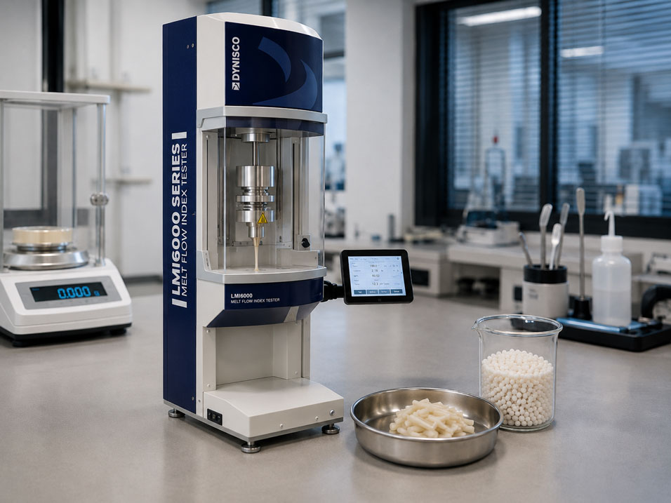
The first three measurements are 11.8, 12.1 and 11.9 g/10 min – the next one suddenly reads 13.4 g/10 min. The material comes from the same batch, the test temperature and weight have not been changed, and the melt flow index tester appears to be functioning correctly. What is causing the variation?
When determining MFR and MVR, repeatability does not depend on the test instrument alone. Differences in material drying, sample quantity, filling and compacting the test barrel, preheating time, temperature stabilisation, extrudate cut interval or cleaning can already influence the result.
It is particularly problematic when several small deviations occur at the same time. A slightly different filling procedure, a small amount of residual material in the die and an inaccurately timed cut may be sufficient to make an otherwise stable material batch appear significantly more variable.
Melt flow index testers for quality control of thermoplastics can be found under Melt flow index testers. Further solutions for plastics processing and polymer testing are grouped under Dynisco products.
Table of Contents
- What do MFR and MVR measure?
- Why must temperature and test load match exactly?
- What role do moisture and sample conditioning play?
- Why does the sample quantity influence the result?
- Correctly controlling compaction and air bubbles
- Why is a consistent preheating time essential?
- Recognising material degradation during the test
- Choosing the correct cut interval for MFR testing
- Correctly evaluating displacement measurement and MVR
- Consistently cleaning the die, barrel and piston
- Typical causes of scattered results
- Recommended test procedure for reproducible values
- Practical example from incoming goods inspection
- Standards compliance and comparability
- Which products and solutions are suitable?
- Conclusion
- Frequently asked questions
What do MFR and MVR measure?
Melt flow testing describes the flow behaviour of a thermoplastic material under defined test conditions. The material is melted in a heated test barrel and forced through a defined die by a loaded piston.
For the MFR – Melt Mass-Flow Rate – the extruded mass is related to a period of ten minutes. The result is usually stated in g/10 min.
In simplified form, the calculation for a defined cut interval can be expressed as:
MFR = 600 × m / t
Here, m is the mass of extrudate discharged during the measurement interval in grams and t is the measurement time in seconds.
The MVR – Melt Volume-Flow Rate – on the other hand, describes the discharged volume per ten minutes and is usually stated in cm³/10 min. In this case, the piston movement or displaced melt volume is measured.
MFR and MVR must therefore not simply be treated as interchangeable values. If the melt density is known, the two quantities can be related to one another. For reproducible testing, however, the respective method and specified test conditions must be clearly defined.
Why must temperature and test load match exactly?
The melt flow index is not a universal material constant that always has the same value regardless of the test conditions. The flow behaviour of a polymer melt strongly depends on temperature and load.
For many thermoplastics, a higher temperature reduces melt viscosity and therefore increases the flow rate. A higher test load also produces a greater force and can result in a significantly different MFR or MVR value.
A measurement result can therefore only be meaningfully compared if at least the following parameters are identical:
- material or material grade,
- test temperature,
- test load,
- test method,
- material conditioning, and
- other test conditions specified for the material.
An MFR value from a data sheet must therefore not be compared with an in-house laboratory value if the temperature or test load differs.
What role do moisture and sample conditioning play?
Sample conditioning is a key influencing factor, particularly for moisture-sensitive or hygroscopic plastics.
If granulate has different moisture contents before testing, the melt flow index values can also vary. In certain polymers, moisture can additionally promote hydrolytic degradation during heating. The polymer chains become shorter, the viscosity decreases and the measured flow value can increase.
A typical example is a situation in which one sample is tested directly from a properly dried material container while a second sample has previously been left exposed in the laboratory for a longer period. Although both samples come from the same batch, their results may no longer be identical.
For comparable tests, the following should therefore be clearly documented:
How was the material stored? Was it dried? At what temperature and for how long? How long was the sample exposed after drying? Was regrind, recycled material or virgin material tested?
This documentation is particularly important in complaint cases. A discrepancy between supplier and processor may otherwise appear to be a material problem even though different conditioning procedures were used.
Why does the sample quantity influence the result?
The amount of material filled into the test barrel should also be kept as consistent as possible from one test to the next.
Different filling quantities influence, among other things, the piston position at the beginning of the actual measurement and the duration for which the material is exposed to heat inside the heated barrel. With thermally sensitive materials, this alone can create a different thermal history.
Too much material can also mean that the relevant measuring range is only reached later. The polymer then remains at the test temperature for longer and may undergo greater changes.
Too little material, on the other hand, can result in insufficient usable piston travel or extrudate being available for the actual measurement.
A consistent sample mass and repeatable filling procedure are therefore often more effective than subsequently applying mathematical corrections to widely scattered measurement results.
Correctly controlling compaction and air bubbles
When granulate is filled into the barrel, gaps inevitably remain between the individual pellets. The material is therefore compacted while the test barrel is being filled.
If the material is compacted very strongly in one test and considerably less in the next, the initial condition of the sample changes. Entrapped air bubbles are even more problematic.
Air can remain trapped during melting and cause bubbles, popping or uneven extrudate as the material exits the die. This can affect both manually cut samples and the reproducible movement of the piston.
Noticeably bubbly extrudate should therefore not simply be evaluated further. First, it should be checked whether the sample has been dried sufficiently and whether the barrel has been filled and compacted evenly.
For comparative measurements, the filling process should be standardised as far as possible: the same quantity of material, the same number of filling steps and a comparable degree of compaction.
Why is a consistent preheating time essential?
After filling, the sample requires time to reach the specified test temperature. This preheating or melting phase is part of the test procedure and must not vary arbitrarily from one measurement to the next.
If the time is too short, the material may not yet have reached a sufficiently uniform temperature. The first measurement section may then have a different viscosity from the subsequent sections.
An unnecessarily long residence time can, on the other hand, be problematic, particularly for thermally sensitive materials. The polymer remains at high temperature for longer and may oxidise, crosslink, hydrolyse or otherwise degrade.
The key is therefore not the assumption that “the longer the preheating time, the better”, but rather the reproducible compliance with the timing specified for the material and test method.
The warm-up phase of the test instrument itself must also be taken into account. The barrel, die and piston should be fully temperature-stable before the test series begins. The fact that the display has reached the setpoint does not necessarily mean that all components are already thermally stabilised at that moment.
Recognising material degradation during the test
A typical fault diagnosis can already be derived from the sequence of several individual values.
If the MFR values continuously increase during a test or between directly consecutive measurement intervals, this may indicate a reduction in melt viscosity. For a sensitive material, it should then be checked whether moisture or excessive thermal exposure is playing a role.
With other materials, however, crosslinking or reaction processes may occur that reduce flow as the residence time increases.
It is therefore important not only to consider the mean value and standard deviation. The chronological sequence of the individual values can also provide valuable information.
| Trend | Possible cause | Recommended check |
|---|---|---|
| Values increase as test time progresses | Possible material degradation or moisture influence | Check drying and residence time |
| Values decrease continuously | Possible material change or crosslinking | Check temperature and time profile |
| One individual value deviates significantly | Possible cutting, weighing or operator error | Check the individual sample and procedure |
| Entire test series is shifted | Check temperature, test load, material condition or instrument condition | Systematically compare the test conditions |
Choosing the correct cut interval for MFR testing
In the gravimetric method, the extrudate exiting the die is cut off at defined time intervals and then weighed.
This makes it immediately clear why the cutting time directly influences the result. If a cut that should occur at a defined point is made noticeably too early or too late, the collected mass changes – and therefore so does the calculated MFR value.
For manual testing, the actual cut and the timing must therefore be performed as synchronously as possible.
The selected interval should also be appropriate for the flow rate. If the extrudate mass is very small, the measurement uncertainty of the balance becomes relatively more significant. A sufficiently large sample mass can reduce the relative weighing uncertainty.
With very high-flow materials, however, the opposite problem occurs: so much material is discharged during a long interval that clean, reproducible manual cuts become more difficult.
An automatic sample cutter can reduce operator influence and improve the timing repeatability of the cuts, particularly in recurring routine tests.
Correctly evaluating displacement measurement and MVR
During an MVR test, the extrudate does not have to be manually cut and weighed for every measurement interval. Instead, the movement of the piston over a defined distance or period of time is measured.
For appropriately equipped instruments, a displacement measuring system or digital encoder is used for this purpose.
However, the measurement is not automatically free from influencing factors. Among other things, it is important that the measurement distance used is suitable for the flow rate and is selected reproducibly for comparative tests.
A distance that is too short reduces the relative resolution of the time or displacement measurement. An excessively long distance, on the other hand, can result in long test times for slow-flowing or thermally sensitive materials.
The melt density is also required to convert or establish the relationship between MVR and MFR. This must not be confused with the solid density or bulk density of the granulate.
Scattered MVR results should therefore not be interpreted solely as an encoder problem. Material filling, preheating time, temperature, piston, die and melt density must also be included in the assessment.
Consistently cleaning the die, barrel and piston
One of the most common and at the same time easiest-to-avoid sources of error is residue from previous tests.
If polymer remains on the barrel wall, piston or inside the die, it can melt again during the next test and mix with the new sample. This is particularly critical when changing materials.
Even a small deposit inside the die bore can influence the effective flow cross-section. In a melt flow test, however, the die is a geometrically defined part of the test. A contaminated or damaged die is therefore not merely a cleanliness issue but can directly alter the test conditions.
After a test, the barrel, piston and die should therefore be cleaned in accordance with the manufacturer’s instructions. How often complete cleaning is required also depends on the polymer being tested.
Consistent cleaning between tests is particularly important for thermally unstable, moisture-sensitive or strongly adhering materials.
Aggressive improvised cleaning methods should also be avoided. The die must not be widened or scratched by the cleaning tool. Otherwise, a cleaning operation can create a permanent geometrical error.
Typical causes of scattered results
| Observation | Likely cause | Check |
|---|---|---|
| Strong variation between repeat measurements | Different sample quantities or compaction | Standardise sample mass and filling procedure |
| Bubbles or popping in the extrudate | Moisture or trapped air | Check material conditioning and compaction |
| First cut significantly different from subsequent cuts | Insufficient temperature stabilisation or incorrect preheating time | Check timing and temperature stability |
| Manual individual samples vary considerably | Cutting time not reproducible | Synchronise cutting and time recording |
| Measurement values implausible after changing materials | Residual material in the barrel or die | Clean the test instrument thoroughly |
| MFR plausible, but MVR or conversion implausible | Incorrect melt density or displacement measurement | Check density value and encoder |
| All values permanently shifted | Incorrect test load, temperature deviation or instrument calibration | Check weights, temperature and instrument condition |
Recommended test procedure for reproducible values
- Define the test specification: Clearly document the material, temperature, load and applicable method.
- Condition the material: Follow the specified drying and storage requirements.
- Stabilise the instrument: Bring the test barrel, die and piston to the test temperature and allow sufficient time for stabilisation.
- Check the die: Ensure that the bore is clean and undamaged.
- Keep the sample quantity constant: Use the same material mass wherever possible for comparable tests.
- Fill reproducibly: Add the material in defined steps and compact it evenly.
- Observe the preheating time: Do not vary the timing based on judgement or feel.
- Remove preheating extrudate: Use only the specified measurement range for the actual evaluation.
- Perform cutting or displacement measurement reproducibly: For MFR, record the cutting time precisely; for MVR, use the specified piston travel.
- Check the trend of the results: Consider not only the mean value but also the sequence of the individual measurements.
- Clean the instrument: Remove residues according to the material and manufacturer’s instructions.
- Document the test: Record temperature, load, method, conditioning and any special observations.
Practical example from incoming goods inspection
A plastics processor checks the MFR of a regularly delivered batch of granulate. The internal target range is narrowly defined. The measurement values had remained stable for several months, but suddenly the results within the same sample begin to vary much more significantly.
An initial check of the instrument shows no obvious temperature deviation. The test weight being used is also correct.
However, when comparing two operators, differences in the procedure become apparent. The first operator weighs the material batch before each test, fills the barrel in several consistent steps and starts the timing according to a defined procedure.
The second operator, however, fills the sample approximately by volume. Some samples are compacted more strongly than others. In addition, the manual extrudate cut is sometimes carried out shortly after the instrument signal rather than exactly at the specified time.
The die inspection also reveals thin polymer deposits from the previous material series.
After thorough cleaning, defining a constant sample mass, standardising the filling procedure and implementing a consistent cutting sequence, the variation is significantly reduced.
The example illustrates a typical case: the test instrument was not defective. The measuring system was technically correct, but the test procedure had not been sufficiently standardised.
For this reason, when MFR values suddenly begin to scatter, the temperature control or electronics should not be adjusted immediately. It is often more useful to systematically observe the complete operating procedure first.
Standards compliance and comparability
ISO 1133 is one of the standards relevant to determining the melt mass-flow rate and melt volume-flow rate of thermoplastics. ASTM D1238 is also widely used.
The specific temperature, load, conditioning and procedure to be used for a particular polymer should be taken from the applicable material standard, test specification or customer specification.
A laboratory should therefore not define one universal preheating time, test mass or test temperature for all plastics.
For comparability between two laboratories, it is likewise not sufficient simply to state “MFR according to ISO 1133” on the test report. The actual test conditions must be clearly traceable.
For materials that are particularly thermally sensitive, it must additionally be taken into account that their rheological behaviour may change during the measurement itself. Such materials may require different or specially designated test procedures.
Which products and solutions are suitable?
Dynisco LMI6000 – automated melt flow index tester
The Dynisco LMI6000 Series is suitable for laboratory, quality control and production environments in which repeatable melt flow testing with reduced operator influence is required.
The integrated electromechanical Auto-Lift handles the test weights reproducibly. Depending on the test configuration, the series supports various test methods. For volumetric measurements, piston movement can be evaluated using displacement measurement.
Automated procedures can help reduce differences between operators, particularly for frequently repeated quality tests.
Dynisco LMI5000 – modular Melt Flow Indexer
The LMI5000 Series has a modular design and, depending on the version, can be expanded with functions for automation and data acquisition.
For the issue described in this article, the available automatic sample cutter is particularly useful. It enables more consistent cuts and can therefore reduce a typical source of operator influence in gravimetric MFR determination.
Additional options such as pneumatic weight lifting, support for consistent material compaction and options for integrating balances and data systems help standardise routine testing.
An overview of the available instruments can be found under Melt flow index testers. Further products for extrusion, plastics processing and polymer testing are grouped under Dynisco products.
ICS Schneider Messtechnik supports you in selecting the appropriate melt flow index tester and suitable equipment as well as in the technical evaluation of MFR and MVR test procedures.
Conclusion
Scattered MFR or MVR values do not automatically mean that the melt flow index tester is operating incorrectly or that the material batch is inhomogeneous.
The test is sensitive to deviations throughout the entire procedure. Material moisture, sample quantity, compaction, preheating time, test temperature, load, cut interval, displacement measurement and cleaning must therefore be considered together.
Especially in manual MFR testing, even a difference in cutting time can visibly alter the individual values. In MVR testing, the manual cutting process is replaced by requirements for reproducible piston travel and time measurement as well as the correct melt density value.
A contaminated die or residual material in the barrel can also distort an entire test series. Cleaning is therefore not merely a cosmetic task but an integral part of reproducible measurement.
The most effective approach when unexpected variation occurs is a standardised test procedure: identically conditioned material, constant sample mass, defined compaction, reproducible preheating time, correct cutting or piston travel and consistent cleaning.
Only once these influencing factors have been ruled out should instrument calibration, temperature control, test weights, displacement measuring system or other technical components be investigated specifically.
Frequently asked questions about scattered MFR and MVR values
Why do MFR values vary within the same material batch?
In addition to actual material differences, variations in sample moisture, sample mass, compaction, preheating time, cutting time or contamination inside the test instrument can increase the scatter.
Can residual moisture change the MFR value?
Yes. Particularly with moisture-sensitive polymers, water can change the material behaviour during heating. Drying and storage of the sample must therefore be reproducible.
Why must the preheating time always be the same?
The preheating time determines the thermal history of the polymer. Times that are too short can result in uneven temperature distribution, while excessively long times can promote material degradation or other changes in sensitive materials.
How does an incorrect cut interval affect the MFR?
The MFR is calculated from the discharged mass and the corresponding time interval. A cut made too early or too late therefore directly changes the calculated result.
Why does an automatic sample cutter improve repeatability?
An automatic cutter can perform the extrudate cut at a more reproducible point in time and therefore reduces a typical source of operator influence in gravimetric testing.
What is the main difference between MFR and MVR?
MFR evaluates the discharged mass per unit of time, while MVR determines the discharged volume per unit of time. For MVR, the piston movement is typically measured.
Does the die have to be cleaned after every test?
The required cleaning frequency depends on the material and test procedure. Particularly consistent cleaning is required for thermally unstable, moisture-sensitive or frequently changing materials. The manufacturer’s and laboratory specifications are authoritative.
Can a contaminated die actually change the measured value?
Yes. Deposits can influence the effective flow cross-section or contaminate the next sample. The die is a defined component of the test system and must be clean and undamaged.
What should I check first if the values suddenly begin to scatter?
First, compare material conditioning, sample mass, filling and compaction, preheating time, cutting procedure and the cleanliness of the barrel, piston and die. Temperature, test weights, balance, displacement measurement and the calibration status of the instrument can then be checked.
Are MFR values obtained at different test temperatures comparable?
No, not directly. MFR and MVR are always linked to defined test conditions. For a meaningful comparison, the temperature, load, material conditioning and test method in particular must be identical.