


IO-Link is a brand name for a communication interface between intelligent sensors or actuators and automation systems. This interface was specified at a meeting of the top suppliers of automation technology. A standardization was created according to the IEC 6113-9 standard.
The benefits of an IO-Link system are the savings in materials and working time, as well as simpler wiring, simpler replacement of devices, as well as advantages in parameterization, remote diagnosis and error identification.
Function
Until now, to get a signal from a sensor, a PLC was mounted on the control cabinet and an analog board group was set, which was wired to the sensor. It became problematic when you had to set several sensors and the control cabinet was also far away. An IO-Link system should solve this.
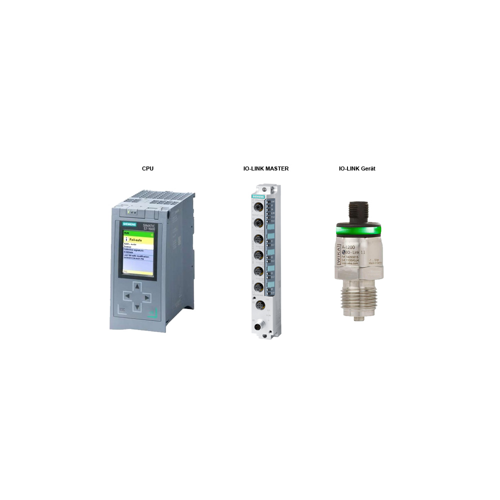
The structure of an IO-Link system consists of: CPU, IO-Link master, IO-Link device (sensors, for example).
The communication between CPU and IO-Link master can take place via different interfaces, such as Profibus and Profinet. The IO-Link master requires an external power supply (24 V DC). The sensors are connected to the master via IO-Link. This is therefore not a fieldbus but a point-to-point communication.
An IO-Link master can be installed directly in the field. Due to the increased degree of protection, a control box is no longer required. There are many ways to communicate with the CPU. The sensors can now be connected to the IO-Link master wirelessly, if necessary using a 3-wire connection. Bidirectional communication enables efficient parameterization as well as extended diagnostics. The speed can be explained by the three communication speeds (4.8kbaud, 38.4kbaud, 230.4kbaud).
Now information can be exchanged via a serial protocol. Among other things, the log consists of measured values, diagnostic data and configuration parameters. What is special is that there is the possibility of an early warning system. Changes in the process are perceived and communicated. In this way, an adjustment can be made in advance, instead of after a defect, as was previously the case.
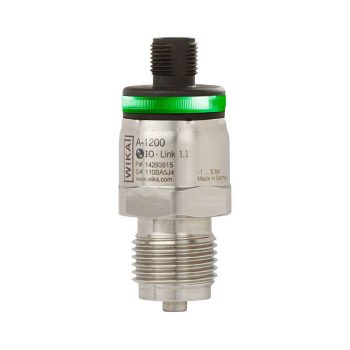
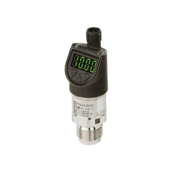
Example pressure sensor A-1200
A good example is the A-1200 pressure sensor from Wika. This can be flexibly programmed via IO-Link and can be used for pressure monitoring as well as for process control. It has an integrated diagnostic function for monitoring to ensure these precise measurement results. Since a digital signal is used, the A-1200 can also be configured externally.
The log is presented in tabular form with very clear error information.
|| Sensor is defective - overpressure - underpressure - overtemperature - undertemperature
In this way you are very directly made aware of process changes. Process failures that would occur in the event of a defect can now be avoided with a timely warning. The same applies to temperature measurement in the sensor electronics, which is intended to prevent deviations in the measured values due to temperature changes.
Other information recorded by the A-1200 is minimum and maximum values of pressure and temperature. This data has been recorded since the device was commissioned. There is also an operating hours counter.
All of these recordings are ongoing.
If the device is reset, all parameters will be overwritten.
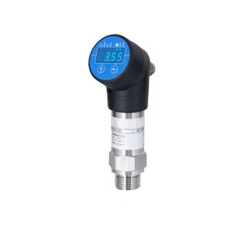
- nominal pressure: 0 ... 0,4 bar bis 0 ... 600 bar relativ, 0 ... 0,6 bar bis 0 ... 600 bar absolut
- accuracy: 0,5 % FSO
- rotatable and configurable display
- parametrization by IO-Link or set menu system (VDMA-conform)
- signal output switchable:
- Smart sensor profile
- IO-Link according to specification V 1.1
- indication of measured values on a 4-digit LED display
- additional information via IO-Link
- Data transfer 38.4 kBaud
 Datasheet Datasheet |
| User Manual |
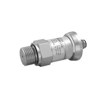
- nominal pressure: 0 ... 600 mbar up to 0 ... 600 bar
- accuracy: 0.5 % FSO
- IO-Link according to specification V 1.1
- Data transfer 38.4 kBaud
- Smart sensor profile
- perfect thermal behaviour
- excellent long term stability
| Datasheet |
| User Manual |
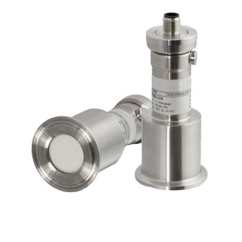
- nominal pressure: from 0 ... 40 mbar up to 0 ... 20 bar
- accuracy: 0.35% (opt. 0.25%) FSO
- IO-Link according to specification V 1.1
- Data transfer 38.4 kBaud
- Smart sensor profile
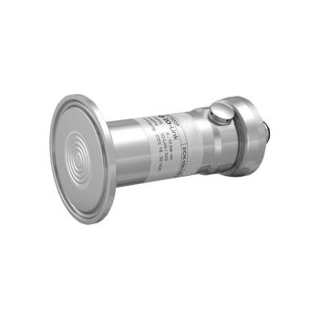
- hygienic version
- ingress protection IP 67/ IP 69
- high overpressure resistance
- diaphragm ceramics Al2O3 (99.9 %)
| Datasheet |
| User Manual |
- nominal pressure: 0 ... 100 mbar up to 0 ... 600 bar
- accuracy: 0.5% / 0.35 % (opt. 0.25 %) FSO
- signal output switchable: IO-Link | PNP | NPN | 0…10V | 4…20mA
- indication of measured values on a 4-digit LED display
- rotatable and configurable display
- parametrization by IO-Link or set menu system (VDMA-conform)
- additional information accessible via IO-Link
- Smart sensor profile
- IO-Link according to specification V 1.1
- Data transfer 38.4 kBaud
| Datasheet |
| User Manual |
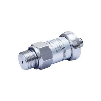
Suitable for almost every industrial application, if medium is compatible with stainless steel 316L
|
Datasheet
|
|
User Manual
|
- nominal pressure: from 0 ... 100 mbar up to 0 ... 40 bar
- accuracy: 0.25% (opt. 0.1%) FSO
- IO-Link according to specification V 1.1
- Data transfer 38.4 kBaud
- Smart sensor profile
- hygenic version
- CIP / SIP cleaning up to 150 °C
- ingress protection IP 67 / IP 69
- diaphragm with low surface roughness
| Datasheet |
| User Manual |
- Industry 4.0-ready IO-Link sensor improves connectivity and diagnostics
- Designed for rough demands of up to 1,000 g shock and -40 ... +125 °C [-40 ... +257 °F]
- Optimised design makes OEM machine integration easier
- Multicolour 360° LED status display simplifies troubleshooting and localisation
| Datasheet |
| User Manual |
- nominal pressure: 0 ... 1 bar up to 0 ... 10 bar, -1 bar ... 0 bar
- IO-Link according to specification V 1.1
- accuracy: 0.5 % FSO
- silicon sensor, RTV
- compact design
| Datasheet |
| User Manual |
- Good/bad indication through parameterisable digital display (red/green)
- Compact size enables easy installation in narrow spaces
- Optimised design makes OEM machine integration easier
- Designed for rough demands of up to 50 g shock and -40 ... +125 °C [-40 ... +257 °F]
| Datasheet |
| User Manual |
- nominal pressure: from 0 ... 100 mbar up to 0 ... 40 bar
- accuracy: 0.5% / 0.35 % (opt. 0.25 %) FSO
- IO-Link according to specification V 1.1
- Smart sensor profile
- Data transfer 38.4 kBaud
- signal output switchable: PNP / NPN / 4 … 20 mA / 0 … 10 V
- indication of measured values on a 4-digit LED display
- rotatable and configurable display
- parametrization by IO-Link or set menu system (VDMA-conform)
- additional information via IO-Link
| Datasheet |
| User Manual |
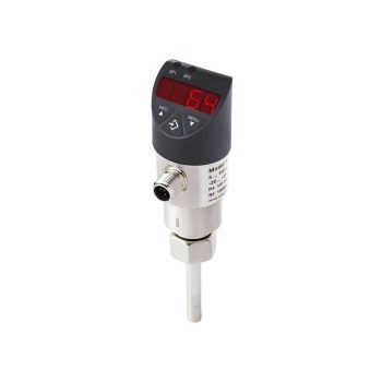
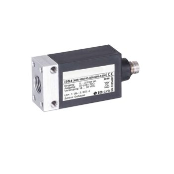
- Wear-free flow monitoring of liquid media using them calorimetric principle
- Flexibly configurable switching and analogue outputs for flow and temperature
- Easily parameterisable via 3-button operation or optionally via IO-Link 1.1
- Exact adaptation to the conditions on-site
|
Datasheet
|
|
User Manual
|