
How does hydrostatic level measurement work?
Each liquid has an individual weight due to different densities and gravity. If the height of the liquid in a container increases, more weight is generated proportionally. This hydrostatic pressure is recorded by the pressure measuring cell of a probe. The pressure is converted into an electrical signal and transformed into an analog or digital output signal by the electronics in the probe.
A major advantage of hydrostatic level measurement is that the measurement is not affected by foam on the surface, turbulence or obstructions. The only thing to consider is the design of the container. Here are the two measuring principles:
|
Open body of water / open container |
Closed container |
 |
 |
|
Hydrostatic pressure dependent on: |
Hydrostatic pressure dependent on: |
|
Liquid Height |
Liquid Height |
|
Liquid Density |
Liquid Density |
|
Air or ambient pressure acting on the liquid (eliminated by integrated relative reference) |
Pressure above the liquid that differs from the ambient pressure |
|
Measurement: |
Measurement: |
|
Probe output signal is adjusted to the liquid |
Two measurements must be taken. A measurement in the liquid, a measurement in the space above. |
|
Scope: |
Scope: |
|
Water Wastewater Aggressive Media Fuels and Oils |
Tank management Biogas plants Filling tanks |
What are the strengths of hydrostatic level measurement?
The hydrostatic level measurement is a versatile, proven measurement method that is constantly being further developed. The use of resistant components ensures trouble-free operation, unaffected by foam on the liquid surface or dirt. This also applies to the physical properties of the media, such as conductivity or viscosity.
Thanks to a large selection of materials for the probes, cables and measuring cells, an enormous range of corrosive, aggressive, viscous or contaminated media can be covered. A capacitive-ceramic measuring cell is used for particularly critical media.
In addition to pressure measurement, other physical parameters can also be optionally recorded, such as temperature.
What types of probes are there for level measurement?
The individual conditions of a level measurement require customized solutions in terms of seals, cables and housings. The following probe designs are available:
Submersible probes
Submersible probes are inserted into the media via a cable and must be positioned close to the ground to provide accurate measurement results. The measuring range extends up to a filling height of 250 m. Depending on requirements, the measuring cell can be made of stainless steel or ceramic. It is secured with a protective cap so that the measuring cell is not damaged if it comes into contact with the ground. The housing of the submersible probe can be made of plastic, stainless steel or an alloy.
Separable immersion probes
With the separable variant, the probe part can be unscrewed without tools. A big advantage is that the entire installation does not have to be removed when replacing.
Separable immersion probes are equipped with a two-stage overvoltage protection. This protects the sensor signal, the signal processing and the signal transmission.
Screw-in probes
Screw-in probes are screwed into the wall of the respective container. In order to prevent the medium from escaping, it is sealed accordingly. With the screw-in probes, the measuring range is up to 60 m. As with the immersion probes, the housing is available in stainless steel or plastic. The measuring cell can be made of stainless steel or ceramic.
What should be considered when choosing a product?
- Medium: which medium, temperature, chemical properties
- Measuring range: maximum level, which density
- Output signal: digital or analogue output signal
- Approval: special certificates required? (e.g. drinking water, SIL, EX protection,...)
- Mounting: maximum cable length, how much space is there, mounting options
What mounting options are there?
|
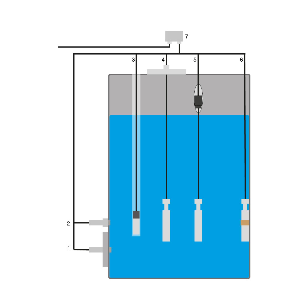
1. Mounting on the tank via probe flange
2. Mounting on the tank via thread 3. Installation in the tank via pipe 4. Installation in the tank - suspension via mounting flange 5. Installation in the tank - suspension via guy clamp 6. Mounting in the tank via clamp 7. terminal box |
 |

- Cost optimized for standard applications
- 22 mm Ø ideal for 1" pipes
- Smallest measuring range: 0…250 mbar / 0…2,5 mH2O
- Largest measuring range: 0…20 bar / 0…200 mH2O
- Negative pressure measuring range: up to -1 bar
- Accuracy ≤ 0,5%
- Analog output: 4…20 mA, 2-wires
0…10 V, 3-wires
0...5 V, 3-wires
0,5...4,5 V, ratiometric - Optionally integrated PT100 / PT1000 Sensor for temperature measurement
 Datenblatt Datenblatt
|
|
Bedienungsanleitung
|