


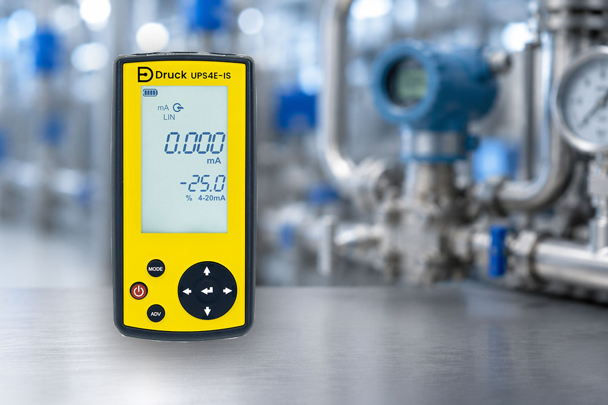
4–20 mA pressure transmitters are among the most widely used measuring instruments in industrial measurement and control technology. They monitor pressures in pipelines, vessels, pumping systems, hydraulic installations, and many other processes. The resulting current signal is then processed by PLCs, process control systems, or display devices and often serves as the basis for control and safety functions.
To ensure these processes operate reliably, the measured values must remain accurate over time. Even minor measurement deviations can lead to quality issues, increased energy consumption, unnecessary maintenance work, or improper control behavior. Regular calibration is therefore essential, especially in quality-critical applications and audit-relevant facilities.
Specialized loop calibrators such as the UPS4E Loop Calibrator are commonly used for the testing and calibration of 4–20 mA pressure transmitters. These devices not only provide precise current measurement but also enable transmitter simulation, loop power supply, and support for HART applications. As a result, calibrations and troubleshooting tasks can be performed much more efficiently than with conventional multimeters.
In this article, you will learn when calibration is required, which test equipment is needed, and how to test and calibrate a pressure transmitter with a 4–20 mA output step by step. Typical sources of error are also discussed, along with a practical calibration example.
Table of Contents
- What Is a 4–20 mA Pressure Transmitter?
- When Should a Pressure Transmitter Be Calibrated?
- What Equipment Is Required for Calibration?
- Calibrating a Pressure Transmitter – Step by Step
- Common Calibration Errors
- Practical Example: Calibrating a 0–10 bar Pressure Transmitter
- Loop Calibrator or Multimeter?
- FAQ on Pressure Transmitter Calibration
- Conclusion
What Is a 4–20 mA Pressure Transmitter?
A pressure transmitter measures the applied process pressure and converts it into an electrical output signal. In industrial automation, this signal is typically transmitted via a 4–20 mA current loop. This measurement principle has become a worldwide standard because current signals can be transmitted reliably and with minimal interference, even over long distances.
Most pressure transmitters operate linearly. The lower range value corresponds to 4 mA, while the upper range value is represented by 20 mA. Intermediate values are displayed proportionally and can be processed directly by PLCs, process control systems, or display devices.
How Does 4–20 mA Signal Transmission Work?
Inside the pressure transmitter is a pressure sensor that detects the applied pressure. The device electronics then convert this measured value into a standardized current signal. This allows equipment from different manufacturers, control systems, and monitoring devices to communicate seamlessly.
The following example shows the typical relationship for a pressure transmitter with a measuring range of 0 to 10 bar:
| Pressure | Output Signal | Measuring Range |
|---|---|---|
| 0 bar | 4 mA | 0% |
| 2.5 bar | 8 mA | 25% |
| 5 bar | 12 mA | 50% |
| 7.5 bar | 16 mA | 75% |
| 10 bar | 20 mA | 100% |
Why Does the Signal Start at 4 mA?
The so-called “live zero” range provides a significant advantage: if the signal drops to 0 mA, the control system immediately recognizes a fault such as a cable break, power supply failure, or device malfunction.
This makes it much easier to detect faults than with older 0–20 mA systems. For this reason, the 4–20 mA standard is used today in almost every industrial sector.
Why Must Pressure Transmitters Be Calibrated Regularly?
Even high-quality pressure transmitters can develop measurement deviations over time. Possible causes include aging electronic components, temperature fluctuations, mechanical stress, or pressure overloads. Even small deviations can negatively impact process quality.
Regular calibration verifies whether the pressure transmitter continues to deliver the correct current values. To do this, the output signal is often measured using a 4–20 mA Loop Calibrator and compared with the theoretical target values.
When Should a Pressure Transmitter Be Calibrated?
A pressure transmitter is often in continuous operation for many years and is exposed to a wide range of environmental conditions. Temperature fluctuations, pressure spikes, vibration, mechanical stress, and aging effects can all reduce measurement accuracy over time. Regular calibrations help identify such changes at an early stage and ensure the reliability of the measurement point.
How often a pressure transmitter should be calibrated depends on the specific application, quality requirements, and operating conditions. While annual calibrations may be sufficient in some industrial plants, other applications require significantly shorter calibration intervals.
Typical Calibration Intervals in Practice
| Application | Recommended Calibration Interval |
|---|---|
| General industrial applications | 12 months |
| Process-critical measurement points | 6 to 12 months |
| Pharmaceutical and food industries | 3 to 12 months |
| Power generation and energy plants | 6 to 12 months |
| Quality-critical measurement points | According to QM or customer requirements |
Many companies define their calibration intervals within the framework of ISO 9001 procedures or internal quality management guidelines. Additional inspections may be required, particularly for safety-related applications.
When Is an Unscheduled Calibration Recommended?
In addition to regular calibration intervals, there are various situations in which an additional verification is advisable.
- After a pressure overload of the sensor
- After repairs or maintenance work
- After replacing the sensor
- After extended plant shutdowns
- In the event of unusual or unstable readings
- Before important audits or acceptance tests
- After modifications to the process or control system
Typical Signs of Measurement Drift
Measurement drift often develops gradually and may go unnoticed during normal operation. It usually becomes apparent only when the transmitter is compared with a reference instrument.
Possible indications of drift include:
- Differences between multiple measurement points
- Implausible pressure readings
- Changes in control system performance
- More frequent alarms or limit violations
- Fluctuating process quality
Calibration or Adjustment?
In practice, these two terms are often used interchangeably, but they describe different procedures.
| Calibration | Adjustment |
|---|---|
| Comparison of target and actual values | Active correction of deviations |
| Documentation of measurement error | Modification of device settings |
| No changes made to the device | Zero or span correction |
| Results are documented | Requires recalibration afterward |
A professional calibration therefore typically begins with determining the existing deviations and, if necessary, adjusting the pressure transmitter. The complete calibration procedure is then repeated to verify the achieved accuracy.
The more critical a measurement point is to the process, the more important regular and documented calibration becomes. It not only ensures reliable measurements but also helps prevent unplanned downtime and quality-related issues.
What Equipment Is Required for Calibration?
Several components are required to calibrate a 4–20 mA pressure transmitter. The goal is to generate a defined pressure, monitor it using a reference instrument, and simultaneously measure the transmitter’s output signal with high accuracy. Reliable calibration results can only be achieved if all test equipment used provides sufficient accuracy.
In practice, a typical calibration setup consists of a pressure source, a reference instrument, and a loop calibrator. Depending on the required accuracy, automatic pressure controllers or specialized calibration systems may also be used.
1. Pressure Source for Generating the Test Pressure
The pressure source generates the defined pressure points required during calibration. The appropriate device depends on the pressure range and the medium being used.
| Pressure Range | Typical Pressure Source |
|---|---|
| Vacuum to approximately 35 bar | Pneumatic hand pump |
| Up to several hundred bar | Hydraulic hand pump |
| High-accuracy applications | Automatic pressure controller |
| Calibration laboratory | Pressure control system |
For many field calibrations, a high-quality hand pump is sufficient. Automatic pressure controllers are typically used when higher accuracy is required.
2. Reference Instrument for Pressure Measurement
The applied test pressure must be monitored using a traceable reference instrument. This reference device serves as the comparison standard during calibration.
Typical reference instruments include:
- Precision pressure calibrators
- Digital reference pressure gauges
- Modular pressure calibrators
- Automatic pressure controllers
As a rule of thumb, the reference instrument should be at least four times more accurate than the pressure transmitter being tested.
3. Loop Calibrator for Measuring the Output Signal
In addition to pressure measurement, the transmitter output signal must also be verified. A loop calibrator is used for this purpose. It measures the actual current value in the 4–20 mA loop and enables direct comparison between target and actual values.
A modern example is the UPS4E Loop Calibrator. This compact handheld instrument combines current measurement and simulation with an integrated loop power supply, HART support, and extensive diagnostic functions.
Key features include:
- Measurement of 4–20 mA signals
- Simulation of current signals
- Integrated 24 V loop power supply
- 250 Ω resistor for HART applications
- Step and ramp functions
- Data logger for up to 100,000 readings
- Voltage measurement up to ±30 V DC
A detailed overview of all technical specifications, measurement ranges, and accuracies can be found in the UPS4E datasheet.
Typical Calibration Setup
In a standard calibration procedure, the pressure transmitter is connected to a pressure source. The applied pressure is monitored by the reference instrument, while the output current is simultaneously measured using the loop calibrator.
The technician then compares the measured current values with the theoretical target values. If deviations are detected, the transmitter zero and span can be adjusted and subsequently verified again.
With this combination of pressure source, reference instrument, and loop calibrator, most industrial pressure transmitters can be calibrated quickly, accurately, and traceably.
Calibrating a Pressure Transmitter – Step-by-Step Guide
The purpose of calibrating a pressure transmitter is to compare the device’s actual output values with the theoretical target values. Defined pressure values are applied while the resulting current signals are measured. Any deviations can then be documented or corrected through adjustment.
Before starting the calibration, all reference instruments used should have valid calibrations. In addition, it is recommended to operate the pressure transmitter under normal conditions for several minutes to allow the sensor and electronics to stabilize thermally.
Step 1: Secure the Measurement Point
Before any calibration work is carried out, all applicable safety regulations must be observed. The pressure transmitter should be isolated from the process or the measurement point should be appropriately shut off.
- Remove or isolate process pressure
- Secure the system against unintended restart
- Verify media compatibility
- Use appropriate personal protective equipment
- Check for residual pressure
Particular care should be taken when working with aggressive media or high-pressure systems.
Step 2: Set Up the Calibration Equipment
The pressure transmitter is connected to the pressure source. At the same time, the reference instrument is connected to accurately monitor the applied pressure.
A loop calibrator is then connected to measure the output signal. Devices such as the UPS4E Loop Calibrator provide high-resolution measurement of 4–20 mA signals and also support troubleshooting of current loops.
A typical calibration setup consists of:
- Pressure source
- Reference pressure instrument
- Pressure transmitter
- Loop calibrator
- 24 V loop power supply (if required)
Step 3: Verify the Zero Point
The lower range value is applied first. For a pressure transmitter with a measuring range of 0 to 10 bar, this corresponds to a test pressure of 0 bar.
| Test Point | Expected Output Current |
|---|---|
| 0 bar | 4.000 mA |
The measured current value is documented and compared with the target value.
Step 4: Verify the Full-Scale Value
The upper range value is then applied.
| Test Point | Expected Output Current |
|---|---|
| 10 bar | 20.000 mA |
The difference between the target and actual value is documented.
Step 5: Check Intermediate Points
To evaluate the linearity of the pressure transmitter, additional test points within the measuring range are applied.
| Range | Pressure | Target Value |
|---|---|---|
| 25% | 2.5 bar | 8.000 mA |
| 50% | 5.0 bar | 12.000 mA |
| 75% | 7.5 bar | 16.000 mA |
For high-quality calibrations, measurements are typically taken during both increasing and decreasing pressure cycles to identify any hysteresis effects.
Step 6: Adjust Zero and Span
If unacceptable deviations are detected, the pressure transmitter can be adjusted. Modern transmitters typically provide functions for zero and span correction.
- Zero adjustment at 0% of range
- Span adjustment at 100% of range
- Reverification of all intermediate points
After each adjustment, the complete calibration sequence should be repeated.
Step 7: Document the Results
Documentation is an essential part of every calibration. It ensures traceability of the results and provides evidence for auditors, customers, and regulatory authorities.
A complete calibration report typically includes:
- Device designation and serial number
- Pressure transmitter measuring range
- Reference instruments used
- Calibration date
- Target and actual values
- Measurement deviations
- Name of the technician
Using a modern loop calibrator enables highly accurate recording of measured values. Technical details regarding measurement and diagnostic functions can be found in the UPS4E datasheet.
Once the calibration has been completed, a reliable assessment of the transmitter’s measurement accuracy is available. This forms the basis for safe and dependable plant operation.
Common Errors When Calibrating Pressure Transmitters
Even high-quality pressure transmitters and precision calibration instruments cannot provide reliable results if the calibration is not performed correctly. In practice, many measurement errors are caused not by the sensor itself but by unsuitable test conditions, wiring issues, or incomplete calibration procedures.
Understanding the most common sources of error helps improve calibration quality and avoid unnecessary repeat testing.
Using the Wrong Measuring Range
One of the most common mistakes is performing the calibration using incorrect target values. For example, if a 0–16 bar pressure transmitter is mistakenly calibrated as a 0–10 bar device, inaccurate results are inevitable.
Before starting any calibration, the nameplate, datasheet, and device configuration should always be checked.
Insufficient Reference Accuracy
The accuracy of a calibration can never exceed the accuracy of the reference instruments being used. If unsuitable reference gauges or calibrators are selected, small deviations may not be detected reliably.
As a general guideline, the reference instrument should be at least four times more accurate than the pressure transmitter being calibrated.
Leaks in the Test Setup
Loose fittings, damaged seals, or poorly fitted adapters can lead to unstable pressure readings. Even minor leaks can significantly affect calibration results, particularly at low pressure ranges or during longer calibration procedures.
For this reason, the entire test setup should be checked for leaks before calibration begins.
Ignoring Temperature Effects
Temperature changes can affect both the pressure transmitter and the reference instruments. After transportation or major changes in ambient conditions, sufficient time should be allowed for all equipment to reach thermal equilibrium.
Otherwise, measurement deviations may occur that are unrelated to the actual performance of the pressure transmitter.
Incorrect Current Loop Wiring
Reversed connections, loose terminals, or a missing loop power supply often result in apparent calibration errors. Such wiring problems are particularly common in older installations.
A loop calibrator such as the UPS4E can help identify and troubleshoot wiring and signal issues quickly and efficiently.
Checking Only Zero and Full Scale
In many cases, only the zero point and full-scale value are checked. As a result, errors in the middle of the measuring range often go unnoticed.
A complete calibration should always include multiple intermediate points to properly evaluate transmitter linearity.
Ignoring Hysteresis
Another common mistake is checking the measuring range in only one direction. High-quality calibrations record values during both increasing and decreasing pressure cycles.
This allows hysteresis effects to be identified, which may remain hidden during a one-way test.
Common Sources of Error at a Glance
| Problem | Possible Cause | Solution |
|---|---|---|
| Measured value too high or too low | Zero point shifted | Perform a zero adjustment |
| Full-scale value incorrect | Span error | Adjust the span |
| Unstable pressure readings | Leak in the test setup | Check for leaks |
| No current signal present | Wiring fault | Inspect the current loop |
| Intermediate values incorrect | Linearity error | Perform a multi-point calibration |
| Fluctuating readings | Temperature or power supply issue | Verify environmental conditions |
A systematic approach, suitable reference instruments, and a complete multi-point calibration help prevent most of these issues. The better the test setup is prepared, the more reliable the calibration results will be.
Practical Example: Calibrating a 0–10 bar Pressure Transmitter
While theoretical calibration procedures are useful, practical examples often provide a much clearer understanding. The following example demonstrates the calibration of a typical pressure transmitter with a measuring range of 0 to 10 bar and a linear 4–20 mA output signal.
Such transmitters are commonly used in water treatment facilities, compressed air systems, pumping stations, hydraulic systems, machinery, and industrial process plants.
Initial Conditions
| Parameter | Value |
|---|---|
| Measured Variable | Pressure |
| Measuring Range | 0 … 10 bar |
| Output Signal | 4 … 20 mA |
| Supply Voltage | 24 V DC |
| Calibration Method | Multi-point calibration |
A pressure source, reference instrument, and loop calibrator are used for the calibration. The current values are measured and documented using the UPS4E Loop Calibrator.
Measurement Results Before Adjustment
After setting up the calibration equipment, the initial measurements are recorded.
| Pressure | Target Value | Measured Value | Deviation |
|---|---|---|---|
| 0 bar | 4.000 mA | 4.082 mA | +0.082 mA |
| 2.5 bar | 8.000 mA | 8.071 mA | +0.071 mA |
| 5.0 bar | 12.000 mA | 12.063 mA | +0.063 mA |
| 7.5 bar | 16.000 mA | 16.052 mA | +0.052 mA |
| 10.0 bar | 20.000 mA | 20.041 mA | +0.041 mA |
The measurements show a systematic positive deviation across the entire measuring range. This indicates a shifted zero point or a slight span error.
Adjusting the Pressure Transmitter
After analyzing the measurement results, the zero point and span are adjusted according to the manufacturer’s instructions. The complete calibration sequence is then repeated.
It is important to verify all test points again after each adjustment. This ensures that the correction has not introduced new deviations elsewhere within the measuring range.
Measurement Results After Adjustment
| Pressure | Target Value | Measured Value | Deviation |
|---|---|---|---|
| 0 bar | 4.000 mA | 4.001 mA | +0.001 mA |
| 2.5 bar | 8.000 mA | 8.000 mA | 0.000 mA |
| 5.0 bar | 12.000 mA | 11.999 mA | -0.001 mA |
| 7.5 bar | 16.000 mA | 16.001 mA | +0.001 mA |
| 10.0 bar | 20.000 mA | 20.000 mA | 0.000 mA |
Evaluation of the Results
After adjustment, all measured values fall within very tight tolerances. The pressure transmitter once again delivers the expected output signals and can continue operating without restrictions.
This example clearly demonstrates how even relatively small deviations can be detected through calibration. Without regular verification, such errors may remain unnoticed for years and potentially affect process quality.
Benefits of Documented Calibration
- Early detection of measurement drift
- Improved process and plant safety
- Higher product quality
- Evidence for auditors and customers
- Reduced unplanned downtime
- Full traceability of measurement results
Particularly for quality-critical measurement points, all calibrations should be properly documented and archived. This creates a complete history of the measurement point, providing valuable information for audits and future analysis.
Loop Calibrator or Multimeter?
A common question is whether a standard multimeter is sufficient for calibrating a pressure transmitter or whether a dedicated loop calibrator is required. While both devices can measure current signals, they differ significantly in functionality and practical usability.
For simple checks, a multimeter may be sufficient. However, when performing calibrations, functional testing, or troubleshooting of 4–20 mA current loops, dedicated loop calibrators offer considerable advantages.
What Can a Multimeter Do?
A digital multimeter is an excellent tool for general electrical troubleshooting. It can measure voltage, resistance, and often current signals as well. For simply verifying the presence of a 4–20 mA signal, this may already be sufficient.
However, when it comes to calibration tasks, a multimeter quickly reaches its limitations because it lacks important signal simulation and testing functions.
What Are the Advantages of a Loop Calibrator?
A loop calibrator is specifically designed for working with 4–20 mA signals. In addition to measurement, it can actively generate and simulate current signals. This allows transmitters, PLC inputs, control systems, and actuators to be tested directly.
One example is the UPS4E Loop Calibrator, which combines numerous functions in a compact handheld device.
Direct Comparison
| Function | Multimeter | UPS4E |
|---|---|---|
| Measure 4–20 mA signals | ✓ | ✓ |
| Simulate 4–20 mA signals | ✗ | ✓ |
| Generate 4–20 mA signals | ✗ | ✓ |
| 24 V loop power supply | ✗ | ✓ |
| HART support | ✗ | ✓ |
| Step function | ✗ | ✓ |
| Ramp function | ✗ | ✓ |
| Data logger | ✗ | ✓ |
| Valve testing | ✗ | ✓ |
| Measurement documentation | Limited | ✓ |
When Is a Multimeter Sufficient?
A multimeter can be useful when you simply need to verify whether a current signal is present or whether a power supply is available. For basic maintenance tasks or initial diagnostics, it is often adequate.
However, once calibration or transmitter adjustment is required, additional functions become necessary that a conventional multimeter generally does not provide.
When Is a Loop Calibrator the Better Choice?
A loop calibrator is particularly recommended for:
- Calibration of pressure transmitters
- Testing temperature transmitters
- Simulation of sensor signals
- Commissioning of new installations
- Troubleshooting 4–20 mA current loops
- Testing PLC inputs
- Valve and actuator testing
- Documented service work
By combining measurement, simulation, loop power supply, and diagnostic capabilities, a dedicated calibrator can replace several individual test instruments and significantly reduce workload.
Technical Information About the UPS4E
Anyone who regularly works with 4–20 mA signals can benefit from the advanced capabilities of a professional loop calibrator. A complete overview of specifications and technical performance can be found in the UPS4E Datasheet.
For occasional electrical measurements, a multimeter remains a valuable tool. However, for calibration, commissioning, and professional troubleshooting, a dedicated loop calibrator is generally the more efficient solution.
FAQ on Calibrating 4–20 mA Pressure Transmitters
What is a 4–20 mA pressure transmitter?
A 4–20 mA pressure transmitter measures applied pressure and converts it into a standardized current signal. The lower range value corresponds to 4 mA, while the upper range value corresponds to 20 mA. This signal can then be processed by PLCs, process control systems, or display devices.
How often should a pressure transmitter be calibrated?
In many industrial applications, a calibration interval of 12 months is common. However, quality-critical or safety-related measurement points may require significantly shorter intervals.
What is the difference between calibration and adjustment?
Calibration involves comparing target and actual values and documenting the results. Adjustment, on the other hand, actively changes the transmitter settings to correct existing deviations.
Why does the signal start at 4 mA instead of 0 mA?
The so-called live-zero range allows faults such as cable breaks or power supply failures to be detected. If the signal drops to 0 mA, the control system immediately recognizes that a fault has occurred.
Can a pressure transmitter be calibrated while installed in the process?
Yes. Many pressure transmitters can be calibrated directly in the plant, provided the measurement point can be safely isolated from the process and a suitable calibration setup can be established.
How accurate should the reference instrument be?
As a general guideline, the reference instrument should be at least four times more accurate than the pressure transmitter being tested. This ensures that the calibration results are not significantly influenced by the reference device itself.
Why do pressure transmitters drift over time?
Measurement drift can result from aging electronic components, temperature fluctuations, mechanical stress, pressure overloads, or environmental influences. Regular calibrations help identify such changes before they affect process performance.
Can I calibrate a pressure transmitter using a multimeter?
A multimeter can measure current signals but is only suitable to a limited extent for calibration tasks. Dedicated loop calibrators are significantly better suited for professional calibration and troubleshooting.
Which loop calibrator is suitable for calibrating pressure transmitters?
Suitable loop calibrators should be capable of measuring and simulating current signals while providing loop power. One example is the UPS4E Loop Calibrator, which also offers HART support, data logging, and advanced diagnostic functions.
How is the linearity of a pressure transmitter verified?
Linearity is evaluated by testing several measurement points across the operating range. Typically, readings are recorded at 0%, 25%, 50%, 75%, and 100% of span and compared with the theoretical target values.
What documentation should be created after calibration?
A complete calibration report should include the device identification, serial number, reference instruments used, test points, target and actual values, measurement deviations, calibration date, and technician information. This ensures full traceability of the results.
Where can I find technical information about the UPS4E?
Detailed specifications, functions, and performance data can be found in the UPS4E Datasheet.