


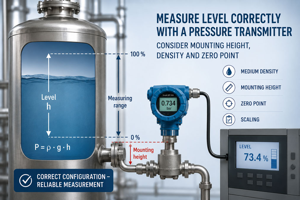
If a pressure transmitter used for level measurement provides incorrect values, the cause is often not the sensor itself. Measurement errors are very often caused by incorrect hydrostatic design, an unconsidered medium density, an incorrect mounting height, an incorrect zero point shift or unsuitable scaling in the control system.
In hydrostatic level measurement, the level is determined via the pressure of the liquid column. This pressure depends not only on the filling height, but also on the density of the medium and the position of the pressure transmitter. If one of these factors is not taken into account correctly, the transmitter may measure the correct pressure, but the calculated level will be wrong.
This article explains why pressure transmitters can display incorrect values in level measurement, how mounting height, density, zero point, tank pressure and scaling are related, and which typical errors occur in tanks, vessels and process plants.
Table of contents
- Basics: Measuring level via hydrostatic pressure
- Why medium density is decisive
- Correctly accounting for the mounting height of the pressure transmitter
- Understanding zero point and zero point shift
- Open tank: Simple hydrostatic measurement
- Closed tank: Accounting for tank pressure
- Venting, breather systems and blocked reference
- Scaling in mbar, bar, mH₂O or percent
- Temperature, density changes and process conditions
- Foam, deposits and dynamic influences
- Diaphragm seals, capillaries and hygienic applications
- Typical errors in level measurement with pressure transmitters
- Table: Fault pattern, possible cause and test step
- Practical example: Tank shows incorrect level despite an intact sensor
- Which pressure transmitter is suitable?
- Conclusion: Level measurement starts with correct design
- FAQ: Frequently asked questions about level measurement with pressure transmitters
Basics: Measuring level via hydrostatic pressure
In hydrostatic level measurement, a pressure transmitter measures the pressure generated by the liquid column above the measuring point. The higher the level, the greater the pressure at the lower measuring point of the tank.
The relationship is basically simple: Pressure increases with filling height and with the density of the medium. At the same filling height, water generates a different pressure than oil, acid, solvent or a food product with a different density.
The pressure transmitter therefore does not measure the level directly, but the pressure. Conversion into litres, metres, percent or volume is then carried out via scaling in the transmitter, display or PLC.
If the displayed level is incorrect, the first step should therefore be to check whether pressure range, density, mounting height and scaling correctly match the application.
Why medium density is decisive
The density of the medium is one of the most important factors in level measurement with a pressure transmitter. A denser medium generates a higher hydrostatic pressure at the same filling height than a lighter medium.
If the measurement is calculated with the wrong density, the displayed level will be systematically incorrect. This is particularly critical for media whose density depends on temperature, concentration, formulation or process condition.
Example: A tank is originally designed for water. Later, another medium with a lower density is filled into the tank. At the same filling height, the pressure is then lower. If the PLC continues to calculate using the density of water, the level will be displayed incorrectly.
For changing media, it must therefore be checked whether fixed scaling is sufficient or whether density compensation or adjusted parameterisation is required.
Correctly accounting for the mounting height of the pressure transmitter
The mounting height of the pressure transmitter directly influences the measured value. The decisive factor is where the measuring diaphragm is located in relation to the lower reference point of the tank.
If the transmitter is installed at the lowest point of the tank, the measured pressure usually corresponds directly to the liquid column above the measuring point. However, if the transmitter is mounted below or above the tank bottom, a zero point shift occurs.
A transmitter mounted below the tank bottom already measures a positive pressure when the tank is empty due to the liquid in the connection line. A transmitter located above the lower reference point only measures pressure once the level is above the measuring point.
The mounting height must therefore be taken into account during design and scaling. Otherwise, the tank will not show 0% when empty or 100% when full.
Understanding zero point and zero point shift
The zero point describes the measured value that should be output when the tank is empty or at the lower level point. With a 4–20 mA signal, the zero point often corresponds to 4 mA.
In practice, however, the pressure in an empty tank is not always 0 mbar. This depends on mounting height, connection line, diaphragm seal, capillary, density of the fill fluid and tank geometry.
A zero point shift is therefore not automatically an error. It only has to be taken into account correctly. The transmitter or PLC must be adjusted so that the actual pressure at an empty tank is assigned to the desired level value.
If the zero point is set incorrectly, the entire level indication is shifted. The tank may then show 8% although it is empty, or it may not reach 100% although it is full.
Open tank: Simple hydrostatic measurement
With an open or vented tank, hydrostatic level measurement is comparatively simple. The pressure transmitter measures the pressure of the liquid column relative to the atmosphere.
It is important that the tank is actually vented. If the vent is blocked or closed, overpressure or vacuum can occur in the tank. This additional pressure falsifies the level measurement.
Gauge pressure transmitters are often used for open tanks. The transmitter compares the process pressure with atmospheric pressure. This means only the liquid column is evaluated.
Typical applications include water tanks, open process vessels, storage tanks, simple storage containers or tanks in water and wastewater technology.
Closed tank: Accounting for tank pressure
In closed or pressurised tanks, a simple gauge pressure transmitter at the bottom is often not sufficient. The transmitter then measures not only the hydrostatic pressure of the liquid column, but also the gas or vapour pressure above the medium.
If this tank pressure fluctuates, the measured value changes even though the level has not changed. This makes the display implausible.
Differential pressure measurement is often used in such applications. The high-pressure side measures the pressure at the lower tank connection, while the low-pressure side records the pressure in the gas space. The difference then corresponds to the liquid column.
For closed tanks, condensate, capillaries, diaphragm seals, temperature differences and the density of the fill fluid must also be considered. This is where many errors occur due to incorrect design.
Venting, breather systems and blocked reference
With gauge pressure transmitters, the reference to atmosphere is important. If the reference opening, vent or cable ventilation is blocked, the transmitter cannot correctly compensate for atmospheric pressure.
This can lead to gradual measurement deviations. Especially in humid, dirty or aggressive environments, venting elements can become blocked or affected by condensate.
The tank itself must also be sufficiently vented in open applications. A blocked tank vent can generate overpressure or vacuum and thereby falsify the level indication.
If the level indication slowly drifts or reacts implausibly to weather and temperature changes, the venting should be checked specifically.
Scaling in mbar, bar, mH₂O or percent
A common error occurs during scaling. The pressure transmitter may, for example, output 4–20 mA for a defined pressure range. The PLC must then correctly convert this signal into level, metres, litres or percent.
For water, mH₂O is often used. One metre of water column corresponds to approximately 100 mbar. For other media, however, this relationship does not apply directly because the density differs.
If a transmitter is designed for 0…400 mbar, this corresponds to approximately 0…4 m filling height for water. With a medium of different density, however, the same pressure corresponds to a different filling height.
Therefore, unit, measuring range and density must match. Errors often occur when bar, mbar, kPa, mH₂O, percent and litres are scaled differently in different systems.
Temperature, density changes and process conditions
Temperature changes can influence level measurement. On the one hand, the density of the medium can change. On the other hand, diaphragm seals, capillaries and fill fluids can cause temperature-dependent effects.
In many standard applications, the influence is small. However, it can become relevant with hot media, large temperature ranges, very accurate measurements or long capillaries.
Process conditions such as stirring, filling, emptying, flow, foam formation or pressure fluctuations can also influence the measurement. The pressure at the measuring point is then not always identical to the static hydrostatic pressure.
For stable measured values, the measuring point should be selected so that direct flow, pump influence, turbulence and mechanical loads are as low as possible.
Foam, deposits and dynamic influences
Foam on the liquid surface usually affects hydrostatic pressure measurement less than optical or radar-based methods, because the pressure is mainly generated by the liquid column. Nevertheless, foam can indicate an unstable process.
Deposits at the process connection or in front of the measuring diaphragm can, however, become problematic. If medium, deposits or crystals collect in front of the diaphragm, pressure can no longer be transmitted correctly.
For pasty, sticky, crystallising or hygienically sensitive media, flush-mounted connections, diaphragm seals or suitable hygienic process connections are often useful.
Dynamic influences such as agitators, pumps, filling jets or fast valve switching can cause pressure fluctuations. In such cases, suitable damping or signal filtering can help without hiding real level changes.
Diaphragm seals, capillaries and hygienic applications
Diaphragm seals are used when the pressure transmitter should not or must not come into direct contact with the medium. This is often the case with aggressive, hot, viscous, crystallising or hygienic media.
A diaphragm seal transmits the process pressure to the sensor via a diaphragm and a fill fluid. With capillary systems, the transmitter can be mounted away from the process.
This design offers many advantages, but also introduces additional influences. Fill fluid, capillary length, mounting height, temperature differences and the density of the fill fluid can influence the zero point and measuring behaviour.
Especially for level measurements with diaphragm seals or capillaries, the design must be carried out carefully. Simple standard scaling is often not sufficient here.
Typical errors in level measurement with pressure transmitters
A common error is assuming that a pressure value directly corresponds to a level. This is only true if density, mounting height, tank pressure and scaling have been taken into account correctly.
Another error is using a gauge pressure transmitter on a closed, pressurised tank. In this case, the gas space pressure is included in the measurement and the level appears incorrect.
Incorrect units also cause problems. If a measuring range is designed in mbar, but the PLC scales it incorrectly as mH₂O or percent, systematic deviations occur.
Other typical errors include incorrect zero adjustment, blocked venting, unconsidered density changes, an unfavourable measuring point, deposits on the diaphragm or incorrectly designed diaphragm seal systems.
Table: Fault pattern, possible cause and test step
| Fault pattern | Possible cause | Next test step |
|---|---|---|
| Tank does not show 0% when empty | Incorrect zero point, transmitter mounted below the reference point or residual pressure present | Check mounting height and zero point |
| Tank does not reach 100% | Measuring range, density or scaling incorrectly set | Check pressure range and PLC scaling |
| Display is proportionally incorrect | Incorrect medium density used | Check density and adjust conversion |
| Display fluctuates in a closed tank | Gas space pressure is included in the measurement | Check differential pressure measurement or pressure compensation |
| Display drifts slowly | Vent blocked, temperature change or diaphragm seal influence | Check reference, venting and process conditions |
| Measured value jumps during stirring or filling | Turbulence, dynamic pressure or unfavourable measuring point | Check measuring point and damping |
| Measured value reacts slowly | Diaphragm seal, capillary, blockage or viscous medium | Check process connection and pressure transmission |
| Measured value remains constant | Diaphragm blocked, connection clogged or transmitter incorrectly scaled | Check process connection and output signal |
Practical example: Tank shows incorrect level despite an intact sensor
In a process vessel, the level is measured via a pressure transmitter at the lower tank connection. However, the display in the PLC still shows around 12% when the tank is empty. When the tank is full, only around 92% is reached. The transmitter is initially suspected of being defective.
During testing, it becomes clear that the pressure transmitter itself is working correctly. The 4–20 mA signal corresponds to the measured pressure. The error lies in the design: The transmitter was mounted below the tank bottom, but the resulting liquid column in the connection line was not taken into account during zero point calculation.
In addition, the PLC calculated with the density of water, although the medium has a lower density. As a result, not only the zero point is shifted, but also the slope of the level indication is wrong.
After correcting zero point, mounting height and density, the scaling is adjusted. The display now shows 0% when the tank is empty and the correct value when it is full. The sensor did not have to be replaced.
Which pressure transmitter is suitable?
For hydrostatic level measurements, pressure transmitters with a suitable measuring range, sufficient accuracy, suitable process connection and media-compatible materials are suitable. The measuring range should match the maximum filling height and density of the medium.
Gauge pressure transmitters are often used for open tanks. For closed or pressurised tanks, a differential pressure transmitter is often required to compensate for the gas space pressure.
For aggressive, hot, viscous, crystallising or hygienic media, flush-mounted process connections, diaphragm seals or hygienic connections may be necessary. Temperature, cleaning, sterilisation and material compatibility must also be taken into account.
The decisive factor is that the transmitter not only matches the pressure range, but the entire measuring task: tank type, medium, density, mounting height, process conditions, signal type and desired display in percent, volume or filling height.
Conclusion: Level measurement starts with correct design
If a pressure transmitter measures incorrectly in level measurement, the sensor is often not the actual cause. Very often, the errors lie in density assumptions, mounting height, zero point, tank pressure or scaling.
Hydrostatic measurement is reliable if the pressure is correctly converted into level. To do this, medium density, maximum level, mounting position, tank type and process conditions must be known.
Anyone who takes these factors into account properly avoids incorrect indications, unnecessary sensor replacements and wrong process decisions. Especially with closed tanks, changing media or diaphragm seal systems, the design should be checked carefully.
FAQ: Frequently asked questions about level measurement with pressure transmitters
How does a pressure transmitter measure level?
It measures the hydrostatic pressure of the liquid column above the measuring point. The level is calculated from pressure, density and mounting height.
Why does my level transmitter show incorrect values?
Common causes include incorrect density, incorrect zero point, unconsidered mounting height, incorrect PLC scaling, tank pressure or an unsuitable measuring point.
What role does density play?
Density determines which pressure is generated at a certain filling height. If the density calculation is wrong, the displayed level will be proportionally incorrect.
What does zero point shift mean?
A zero point shift occurs when the pressure in an empty tank is not 0 mbar, for example due to mounting below the tank bottom or filled connection lines.
Can a gauge pressure transmitter be used on a closed tank?
Only if the gas space pressure is constant or taken into account separately. If the tank pressure fluctuates, differential pressure measurement is usually required.
Why does the tank not show 0% although it is empty?
The zero point may be set incorrectly, the transmitter may be mounted below the reference point or residual pressure or a liquid column in the connection line may be present.
Why does the display not reach 100%?
Possible causes include incorrect measuring range, incorrect density, faulty scaling or an upper level point that has not been correctly taken into account.
What must be considered with diaphragm seals?
Diaphragm seals and capillaries can influence zero point, response time and temperature behaviour. They must be designed to match the application.
Which unit is useful for level measurement?
Depending on the application, mbar, bar, kPa, mH₂O, percent, metres or litres are used. It is important that pressure range, density and scaling match.
Does temperature influence level measurement?
Yes, temperature can change the medium density and cause additional effects in diaphragm seal systems. This should be considered when high accuracy is required.
What should be done with fluctuating level values?
Measuring point, venting, agitators, pump influences, tank pressure, damping and electrical signal processing should be checked.
When is a differential pressure transmitter necessary?
A differential pressure transmitter is usually necessary when the level in a closed or pressurised tank is to be measured and the gas space pressure can fluctuate.