


Sporadic voltage dips are among the most unpleasant faults in electrical systems. During a normal measurement, everything appears normal, the voltage seems correct, and yet a control system fails, a relay chatters, a power supply goes into fault mode or a machine shows sporadic error messages. This is exactly where a simple momentary measurement with a multimeter is often not enough.
Many voltage dips last only a few milliseconds or seconds. They occur when large consumers are switched on, when contactors energize, during motor starts, due to loose terminals, ageing power supplies or short-term load peaks. Anyone who is not looking at the measuring instrument at exactly that moment will miss the fault.
Modern digital multimeters with Min/Max function and data logger help make such events visible. They do not only capture the current value, but store the lowest and highest measured value or record the voltage curve over a longer period of time. This article explains how these functions help in practice and what should be considered when troubleshooting in the control cabinet.
Table of contents
- Basics: Why voltage dips are difficult to find
- Typical causes of short-term voltage drops
- Why a normal momentary measurement is often not enough
- Min/Max function: Making the lowest voltage value visible
- Data logger in the multimeter: Recording the voltage curve over time
- Troubleshooting in the control cabinet: 24 V, power supplies, relays and terminals
- TRMS, measurement category and safe measurement
- Comparing measured values with system events
- Table: Typical fault patterns and possible causes
- Practical example: Sporadic voltage drop in a 24 V control system
- Table: Which multimeter function helps when?
- Which measuring instruments / products are suitable?
- Conclusion: Short-term voltage dips require time-based measurement
- FAQ: Frequently asked questions about measuring voltage dips
Basics: Why voltage dips are difficult to find
A voltage dip is a short-term drop in the supply voltage. This can occur in a 230 V network, in a 400 V distribution system, in a 24 V DC control system or directly at individual consumers in the control cabinet. What matters is not only how far the voltage drops, but also how long the dip lasts and which device is affected by it.
Many controllers, relays, sensors, power supplies and electronic modules tolerate short-term deviations only to a limited extent. A brief dip can already be enough for a relay to drop out, a frequency inverter to report an undervoltage fault, a PLC input to react incorrectly or communication to be briefly interrupted.
The difficulty is that the fault is often not permanently present. During the measurement, the multimeter may show 24.1 V DC or 230 V AC. However, at the moment of a motor start, when a solenoid valve is switched on or during mechanical vibration at a loose terminal, the voltage can briefly drop significantly.
For such faults, it is therefore not enough to look only at a single momentary value. The voltage curve is important: What was the lowest value? When did it occur? Does the dip correspond to a switching operation, an inrush current, a machine movement or a load change?
Typical causes of short-term voltage drops
Voltage dips are often caused by load changes. When motors, heaters, solenoid valves, contactors, pumps or compressors switch on, the current can briefly increase significantly. If the supply is tightly dimensioned or if cables, power supply or terminals are unfavorable, the voltage drops for a short time.
Another common cause is loose or oxidized terminals. Such faults are particularly tricky because they are hardly noticeable at rest. Only under load or during vibration does a voltage drop occur across the poor connection. The result can be a sporadic fault that cannot be reliably found with a normal visual inspection.
Power supplies can also cause problems. A 24 V power supply may appear clean at no load, but collapse under load. Causes can include overload, ageing, thermal stress, insufficient power rating, defective capacitors or consumers connected in parallel.
Relays and contactors can also be part of the problem. When a coil energizes, a short-term current demand occurs. If several contactors switch at the same time or if one supply powers several consumers simultaneously, a short voltage dip can occur and trigger a fault elsewhere in the system.
Why a normal momentary measurement is often not enough
A normal voltage measurement shows the value at the moment when the multimeter captures and displays it. This is sufficient for stable conditions. For sporadic voltage dips, however, this method is often too slow or too random.
The fault can occur exactly between two reading moments. The display then shows a normal value again, even though the voltage briefly dipped just before. Especially with sporadic system faults, this creates the impression that the supply is fine.
In addition, many system events cannot be predicted exactly. A contactor only energizes occasionally, a motor starts at irregular intervals or a fault occurs only under a certain load. Manual observation over a longer period is impractical and unreliable.
This is why the Min/Max function and data logger are so helpful. They take over observation over a longer period of time. The measuring instrument stores the lowest and highest value or records the curve. This makes visible what actually happened during the unobserved time.
Min/Max function: Making the lowest voltage value visible
The Min/Max function of a multimeter stores the smallest and largest measured value during a measurement. When searching for voltage dips, the Min value is especially interesting. It shows how far the voltage has dropped at least once since the measurement was started.
Example: In normal operation, 24.2 V is measured on a 24 V DC supply. After ten minutes, however, the Min function shows 18.7 V. This makes it clear that at least one short-term dip occurred, even if the current display value is normal again.
The Min/Max function is particularly useful for quick initial narrowing down. It answers the question: Are there short-term deviations at all? If the Min value remains stable, the fault may not be in the voltage supply. If the Min value drops significantly, a more detailed analysis is worthwhile.
It is important to perform the measurement at the right point. A voltage dip at the power supply output means something different from a dip directly at the PLC input, at the consumer or downstream of a terminal. The closer the measurement is taken to the affected device, the better it can be assessed whether a critical voltage drop actually reaches it.
Data logger in the multimeter: Recording the voltage curve over time
While the Min/Max function mainly shows extreme values, a data logger provides the time curve. This is particularly helpful when not only the lowest value is of interest, but also the time, duration and frequency of the voltage dip.
With a recording, it becomes possible to see whether the voltage drop occurs regularly, whether it is linked to certain machine cycles or whether it slowly increases with rising load. A single Min value shows, for example, that a dip was present. The logger additionally shows when and how often it occurred.
For meaningful recording, the measuring duration must match the fault situation. If the fault occurs only once per shift, a measurement over a few minutes is not sufficient. If the fault occurs during motor start-up, a targeted recording during the start-up process is often enough.
The measuring interval is also important. If recording is too slow, very short events may be missed or shown in a weakened form. If recording is very fast, more data is generated and must later be evaluated. The setting should therefore match the expected fault duration.
Troubleshooting in the control cabinet: 24 V, power supplies, relays and terminals
In control cabinets, voltage dips often occur on the 24 V DC side. This supply powers PLCs, sensors, relays, valves, operating panels and communication modules. If several consumers switch at the same time, a power supply that is too tightly dimensioned or poor wiring can quickly become visible.
A useful test setup usually starts at the power supply output. There, it is checked whether the supply itself remains stable. Then measurements can be taken closer to the affected consumer. If everything is stable at the power supply, but a dip occurs at the consumer, the cause is more likely to be in the cable, terminal, fuse, connector or distribution.
For relays and contactors, the switching time should also be considered. If a voltage dip occurs exactly when a coil energizes or when a load circuit is switched on, the link to the load change is obvious. In such cases, a separate supply, a stronger power supply, different wiring or time-delayed switching can help.
Loose terminals are particularly critical. Under load, they can cause a voltage drop without being noticeable at rest. A measurement directly before and after a terminal or connection can show whether a voltage drop occurs there. Work in the control cabinet may only be carried out by qualified personnel.
TRMS, measurement category and safe measurement
For AC voltages, a True RMS multimeter is important when there is no clean sine waveform. In modern systems with frequency inverters, switched-mode power supplies, pulsed consumers or non-linear loads, simple average-responding measuring instruments can display misleading values. A TRMS multimeter evaluates the RMS value much more reliably, even with distorted signals.
The appropriate measurement category is just as important. Measurements in distribution boards, control cabinets, on feeders or near high short-circuit powers place different safety requirements than measurements on small electronic modules. The multimeter, test leads and test probes must match the measuring point.
Safe handling is also crucial. Voltage dips are often searched for during operation. This means that measurements are taken under voltage and switching operations can occur during the measurement. Test leads must be securely connected, must not slip off and must not cause short circuits.
For electrical measurements on systems, the following applies: Only qualified personnel should carry out measurements. Before measuring, the measurement category, voltage level, personal protective equipment, test leads and system condition must be assessed. Troubleshooting must not create an additional safety risk.
Comparing measured values with system events
A data logger is particularly valuable when the recorded voltage values are compared with system events. A voltage dip alone is an indication. The actual cause often only becomes clear when the time coincides with a motor start, a valve switching operation, a relay changeover, a door operation or a fault message.
For this reason, it should be noted during the measurement when important events occur. In automated systems, PLC status, fault messages, switching times or process data can also be used. If voltage drops always correspond to the same system action, the cause can be narrowed down much faster.
For sporadic faults, the recording duration is decisive. Sometimes measurements must be taken over several hours or an entire shift. The data logger takes over the task that an operator cannot reliably perform manually: continuous observation and storage.
The evaluation should not focus only on the lowest voltage value. Frequency, duration and repeatability are also important. A single brief dip has a different significance than regularly recurring voltage gaps during every machine cycle.
Table: Typical fault patterns and possible causes
| Fault pattern | Possible cause | Useful measurement |
|---|---|---|
| PLC restarts sporadically | 24 V supply briefly collapses | Min/Max or logger measurement directly at the PLC supply input |
| Relay chatters during switching | Coil voltage drops below holding voltage | Record voltage at the relay coil during the switching operation |
| Fault occurs only during motor start | Inrush current causes voltage dip | Compare mains voltage and control voltage during start-up |
| Sensors briefly deliver incorrect signals | Supply at the sensor briefly drops | Measure voltage directly at the sensor connection or distributor |
| Fault during vibration or movement | Loose terminal, cable break or plug contact | Compare voltage before and after the connection during operation |
| Fault after longer running time | Power supply heats up or is overloaded | Long-term recording of output voltage and load states |
Practical example: Sporadic voltage drop in a 24 V control system
In a machine, the PLC briefly fails about two to three times per day. During inspection in the control cabinet, the 24 V supply shows an apparently normal value of 24.0 V. The power supply also initially appears unremarkable. A normal momentary measurement therefore provides no clear indication.
The technician connects a digital multimeter with Min/Max function directly to the PLC supply input. After a few hours, the Min value shows a brief drop to 17.9 V. This makes it clear that the PLC is actually seeing a critical voltage dip.
In the next step, the measurement is repeated at the power supply output. There, the voltage remains significantly more stable. The fault is therefore probably not directly in the power supply, but on the way to the PLC. A further measurement at an intermediate terminal shows that a voltage drop occurs across a loose terminal when a solenoid valve switches.
After tightening and checking the connection, the Min value remains stable over several production cycles. The example shows why a pure momentary measurement would not have been sufficient. Only Min/Max recording and measurement at several points in the measuring chain make the cause visible.
Table: Which multimeter function helps when?
| Function | Suitable for? | Practical benefit |
|---|---|---|
| Momentary measurement | Stable voltages and quick plausibility check | Shows the current state, but not short events |
| Min/Max function | Making short-term dips or peaks visible | Stores the lowest and highest value during the measurement |
| Data logger | Documenting the curve over a longer period | Shows time, frequency and curve of voltage dips |
| Bar graph | Observing fast trends and changes | Helps detect dynamic changes when numerical values appear too sluggish |
| TRMS measurement | Measuring AC voltage with distorted waveforms | Provides more reliable RMS values for non-sinusoidal voltages |
Which measuring instruments / products are suitable?
For finding short-term voltage dips, a digital multimeter with Min/Max function, data logger, bar graph and True RMS measurement is particularly helpful. These functions do not only support a single measurement, but help make sporadic events visible over time.
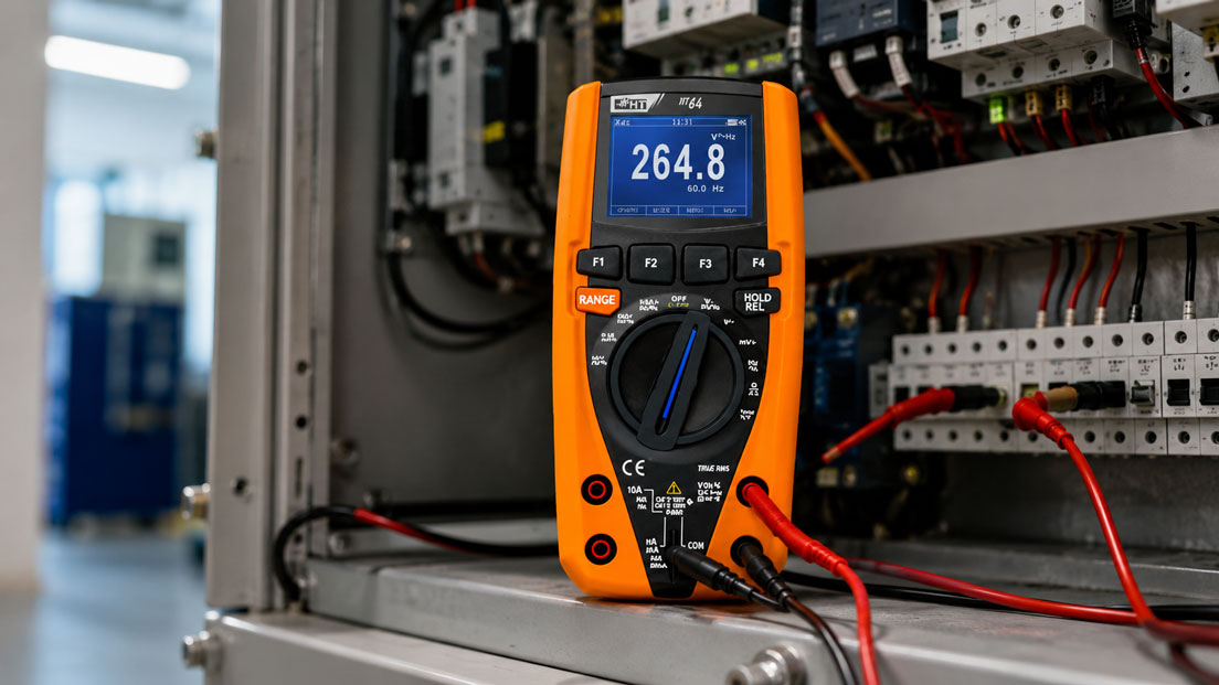
A suitable device for such tasks is the HT64 digital multimeter TRMS. It is suitable for users who want to measure voltages, currents and other electrical quantities while also using Min/Max values, data logger function and bar graph.
Especially in control cabinets, maintenance, building services and service work, it is important that the measuring instrument matches the measuring point. In addition to functionality and resolution, measurement category, test leads, safe contacting and operability during running operation must also be considered.
During troubleshooting, the multimeter should not be used at just one point. It is more meaningful to check the voltage curve step by step along the supply: at the power supply, at distribution terminals, downstream of fuses, directly at the consumer and at the points where the fault is suspected.
Conclusion: Short-term voltage dips require time-based measurement
Voltage dips are often difficult to find with a simple momentary measurement. The fault occurs briefly, disappears again and remains invisible in the normal display value. Min/Max function and data logger make such events much easier to detect.
The Min/Max function shows whether a critical minimum value has occurred at all. The data logger additionally shows when, how often and in which context the voltage dip occurred. Together with system events, switching operations and load states, the cause can be narrowed down much more precisely.
With a suitable TRMS digital multimeter such as the HT64, a safe measurement strategy and systematic checking of power supply, terminals, cables and consumers, sporadic voltage drops in the control cabinet can be detected and resolved much more reliably.
FAQ: Frequently asked questions about measuring voltage dips
What is a voltage dip?
A voltage dip is a short-term drop in the supply voltage. It can be so brief that it is not noticed during a normal momentary measurement, but it can still affect controllers, relays, power supplies or electronic modules.
Why can’t I find the fault with normal voltage measurement?
A normal measurement usually shows only the current value. If the dip occurs only briefly, it can fall between two reading moments. The voltage then appears normal again, even though a critical event has occurred.
What does the Min/Max function show?
The Min/Max function stores the lowest and highest measured value during the measurement. For voltage dips, the Min value is especially important because it shows how far the voltage dropped at least once.
When is a data logger useful?
A data logger is useful when the fault occurs sporadically or when the curve over a longer period is of interest. It shows not only the lowest value, but also time, frequency and curve of the voltage fluctuation.
Where should I measure in the event of a 24 V fault?
Several measuring points are useful: directly at the power supply output, at distribution terminals, downstream of fuses and directly at the affected consumer or PLC input. This makes it possible to identify where the voltage drop occurs.
Can a power supply look fine at no load and collapse under load?
Yes. A power supply can provide the correct voltage at rest, but briefly collapse during load peaks, heating or overload. Measurements should therefore be taken under real operating conditions wherever possible.
How do I identify a loose terminal as the cause?
A loose terminal often causes a voltage drop only under load. Measure the voltage before and after the connection during operation. If a difference occurs there, the connection is suspicious.
Why do voltage dips often occur during motor start?
During motor start, a high inrush current can flow. This current can cause a short-term voltage drop in the mains or control voltage supply, especially if the supply or cables are tightly dimensioned.
What does TRMS mean on a multimeter?
TRMS means True Root Mean Square. A TRMS multimeter measures AC voltages more reliably when the waveform is distorted by frequency inverters, switched-mode power supplies or non-linear loads.
Why is the measurement category important?
The measurement category indicates the electrical environment for which a measuring instrument is designed. Measurements in control cabinets, distribution boards or feeders require the appropriate measurement category, suitable test leads and safe test probes.
How long should a logger measurement run?
The measuring duration should match the fault frequency. If the fault occurs every few minutes, a short measurement is sufficient. If it occurs only once per shift, recording must be correspondingly longer.
Can a data logger always capture very short dips?
This depends on the measuring rate, logger setting and event duration. Very short voltage dips can be missed or displayed only in a weakened form if the recording is too slow.
Why should measured values be compared with system events?
The timing of the voltage dip is often the key to the cause. If the dip always occurs when a valve switches, during motor start or during a specific machine movement, the fault can be narrowed down much faster.
Can the bar graph help with troubleshooting?
Yes. A bar graph often shows fast trends more clearly than a pure numerical value. It does not replace recording, but it can be helpful when observing dynamic changes.
What is the most important practical tip?
Do not measure only where the voltage is generated, but also where the affected device is supplied. Only comparing several measuring points shows whether the voltage dip occurs at the power supply, in the distribution, at a terminal or directly at the consumer.