


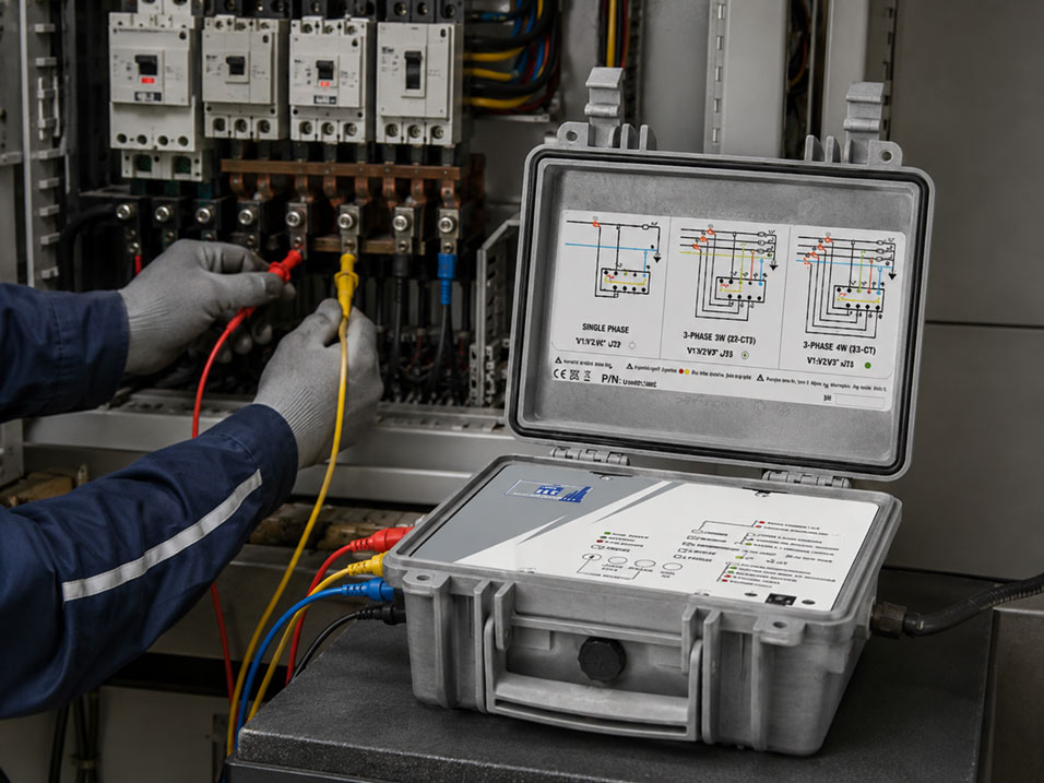
A three-phase power or network analyser can measure active, reactive and apparent power, energy consumption, power factor, current imbalance and power quality. However, this requires the voltage leads and current sensors to be assigned clearly to the correct phases.
Even one reversed current sensor can cause one phase to display negative active power. If the current from L2 is evaluated together with the voltage from L1, incorrect phase angles, unrealistic power factors and significantly distorted total power values result.
The direction of the current clamp is also crucial. For a conventional load, the direction arrow on the sensor normally points from the supply towards the load. A clamp installed in the opposite direction reverses the sign of the measured power.
This article explains how to prepare, connect and check a three-phase power analysis systematically for plausibility. Work on electrical installations may only be performed by appropriately qualified electricians using suitable personal protective equipment and measuring equipment.
Table of contents
- Why voltage and current must be measured together
- Selecting the correct network configuration
- Assigning voltage and current channels correctly
- Observing the direction of the current sensors
- Current clamps, Rogowski coils and fixed current transformers
- Correctly assessing negative active power
- Checking power factor and phase angle
- Distinguishing star and delta networks
- Safe and systematic connection
- Plausibility check before recording
- Typical connection errors
- Practical example: One phase shows negative power
- Which measuring instruments / products are suitable?
- Conclusion
- Frequently asked questions about three-phase power analysis
Why voltage and current must be measured together
For a simple current measurement, it is sufficient to measure the current flowing through a conductor. Electrical power, however, cannot be determined reliably from this value alone.
A power analyser simultaneously requires:
- the instantaneous voltage waveform
- the instantaneous current waveform
- the phase relationship between the two signals over time
In simplified terms, active power results from voltage, current and the phase angle between the two quantities. For sinusoidal signals, the following applies to a single phase:
P = U × I × cos φ
For distorted current or voltage waveforms, this simplified approach is not sufficient. Modern power analysers therefore record the actual waveforms and calculate active, reactive and apparent power as well as the power factor.
For this calculation to be correct, voltage and current must be assigned to the same phase. Current sensor I1 belongs to voltage U1 or L1, I2 to L2 and I3 to L3.
Selecting the correct network configuration
Before connection, the existing network configuration must be identified clearly. The analyser configuration determines which voltages are measured and how the power values are calculated.
| Network configuration | Typical conductors | Basic measurement |
|---|---|---|
| Three-phase four-wire network | L1, L2, L3 and N | Voltages to N and currents in the three line conductors |
| Three-phase three-wire network | L1, L2 and L3 | Line-to-line voltages and line currents |
| Balanced three-phase load | Three or four conductors, depending on the installation | Simplified measurement methods only for genuinely balanced loads |
| Single-phase measurement | L and N or two active conductors | One voltage channel and one current channel |
A four-wire network must not accidentally be configured as a three-wire network. Likewise, an existing neutral conductor must not simply be treated as a protective conductor or arbitrary reference point.
In networks with voltage transformers, the correct transformation ratio must also be configured. Otherwise, the measured secondary voltage may appear correct while the displayed primary voltage and power are incorrect by the transformer factor.
Assigning voltage and current channels correctly
The most important connection rule is:
Each current channel must be assigned to the voltage path of the same phase.
| Conductor | Voltage input | Current input |
|---|---|---|
| L1 | U1 or V1 | I1 |
| L2 | U2 or V2 | I2 |
| L3 | U3 or V3 | I3 |
| N, if measured | N as voltage reference | Separate neutral-current channel |
The colours of the test leads make assignment easier, but do not replace verification. In older installations, conductor colours may differ from current conventions or may have been assigned incorrectly after modifications.
If, for example, the voltage from L1 is evaluated together with the current from L2, the analyser measures an incorrect angle between the two quantities. Possible consequences include:
- a very low or negative power factor
- implausible reactive power
- negative active power on an individual phase
- significantly understated or overstated total power
Checking the current magnitude alone is therefore not sufficient. Three plausible current values may still be assigned to the wrong voltages.
Observing the direction of the current sensors
Current clamps and flexible current sensors usually have a direction arrow or markings for source and load. For a conventional load, this arrow points from the supply towards the load.
If the sensor is installed in the opposite direction, the current magnitude generally remains the same. However, the phase relationship is rotated by 180 degrees. The active power therefore appears with the opposite sign.
Typical indications of a current clamp installed in the wrong direction include:
- negative active power on only one phase
- negative energy consumption for a conventional load
- an unusual phase angle
- the active power values of the three phases partially cancelling each other out
However, the arrow direction is not automatically incorrect merely because negative power is displayed. In photovoltaic systems, generators, regenerative frequency converters or regenerative drives, power may genuinely flow back towards the supply.
Before reversing the sensor, it must therefore be clarified whether the measured part of the installation is currently operating as a load or a generator.
Current clamps, Rogowski coils and fixed current transformers
Conventional current clamps or flexible Rogowski current sensors are frequently used for portable power analyses.
Conventional current clamps
Current clamps with a split iron core are compact and suitable for many standard measurements. The clamp core must be closed completely. Contamination or a small air gap at the contact surfaces can influence the measured value.
Flexible current sensors
Flexible current sensors can be installed around large busbars and conductors in confined control cabinets. The closure must be secured completely, and the loop must not be excessively twisted or mechanically stressed.
The correct sensor type and measuring range must be selected on the analyser. If, for example, a 1,000 A sensor is used while the analyser is configured for 100 A, the displayed current and power values will be incorrect by a corresponding factor.
Fixed current transformers
Conventional current transformers with a 1 A or 5 A secondary output have defined primary and secondary polarity. Common markings are P1/P2 or K/L on the primary side and S1/S2 or k/l on the secondary side.
The polarity must be observed consistently for all three transformers. The transformation ratio must also be configured correctly in the measuring instrument.
Important: The secondary circuit of a conventional current transformer must not be operated open-circuit while primary current is flowing. Dangerous high voltages may occur. Suitable short-circuiting terminals and a professional procedure are required for work on the secondary circuit.
This hazard must be distinguished from the usual flexible current sensors used with portable power analysers. The operating instructions for the current sensor and measuring instrument are always decisive.
Correctly assessing negative active power
Negative active power may have various causes.
| Observation | Probable cause |
|---|---|
| One phase negative, two phases positive | Current sensor on one phase reversed or phases assigned incorrectly |
| All three phases similarly negative | All sensors reversed or genuine power export |
| Individual phases differ significantly | Phase interchange, unbalanced load or measuring-range error |
| Sign changes with the operating condition | Possible genuine reversal of the power-flow direction |
For a motor without regenerative capability, a permanently negative phase is usually implausible. On a test bench operating in generator mode or with a regenerative drive, however, the negative sign may be correct.
An automatic function for digitally reversing the current direction can simplify troubleshooting. However, it should not be used merely to make an unverified connection appear correct mathematically.
Checking power factor and phase angle
The power factor is an important aid for checking the connection. For many conventional three-phase loads, the values of the three phases should at least be within a similar range.
Very different or negative values may indicate the following problems:
- current sensor installed in the wrong direction
- current and voltage from different phases combined
- incorrect network configuration selected
- strongly unbalanced or non-linear load
- genuine power export
Power factor and cos φ are not necessarily identical for distorted signals. Frequency converters, switched-mode power supplies and other non-linear loads generate harmonics. In this case, the total power factor takes signal distortion into account in addition to the phase displacement.
A low power factor is therefore not automatically a connection error. It must be assessed together with the current waveforms, active power, reactive power and harmonics.
Distinguishing star and delta networks
In a four-wire star network, the line-conductor voltages can be measured against the neutral conductor. In a 400 V network, approximately 230 V between a line conductor and neutral and approximately 400 V between two line conductors are typical.
In a three-wire network without a neutral conductor, the line-to-line voltages are measured instead. The analyser must be configured accordingly.
Depending on the network configuration and measuring instrument, different measurement methods using two or three current sensors may be available. Simplified methods may require a balanced load or a particular circuit arrangement.
For general troubleshooting on unbalanced industrial installations, complete measurement of all three phases is usually more informative. However, the specific connection method must always correspond to the wiring diagram in the operating instructions for the analyser being used.
Safe and systematic connection
Measurements are frequently carried out in open low-voltage distribution boards with high prospective short-circuit currents. In addition to the rated voltage, the appropriate measurement category is therefore crucial.
At least the following points must be clarified before work begins:
- network configuration and rated voltage
- expected currents
- measurement category and voltage rating of the complete equipment
- available connection and fastening points
- required personal protective equipment
- hazards caused by arc flash and short circuits
Wherever possible, test leads and sensors should be connected while the installation is de-energised. If this is not operationally possible, the applicable working procedures and protective measures must be observed.
The basic procedure is:
- Select the network configuration: Configure a three-wire, four-wire or other circuit on the analyser.
- Configure the current sensors: Enter the sensor type, measuring range and, where applicable, transformer ratio.
- Identify the conductors: Clearly determine L1, L2, L3 and, where applicable, N.
- Connect the voltage: Connect the test leads according to the connection diagram.
- Install the current sensors: Place I1 on L1, I2 on L2 and I3 on L3.
- Check the direction: Align all arrows consistently in the intended power-flow direction.
- Secure the leads: Prevent unintentional disconnection and contact with moving parts.
- Check the live values: Verify all phase values before starting the long-term recording.
The specific sequence for connecting and removing the test leads depends on the operating instructions for the respective instrument and the company’s safety requirements.
Plausibility check before recording
A measurement campaign lasting several days should only be started after the instantaneous values have been checked for plausibility.
The following values are particularly important:
- voltages of the three phases
- currents and expected load distribution
- phase sequence L1, L2 and L3
- active power per phase and total active power
- reactive and apparent power
- power factor per phase
- vector diagram or phasor display
For a typical load, the phase power values should generally have the same sign. Significantly different angles or one individual negative phase must be investigated before recording begins.
An approximate comparison calculation is also useful. For an approximately balanced three-phase load, the active power can be estimated as follows:
P ≈ √3 × ULL × I × cos φ
If the analyser deviates from the expected machine power by a multiple, the sensor range, transformer factor, network configuration and phase assignment should be checked again.
Typical connection errors
| Error | Possible effect | Better approach |
|---|---|---|
| I1 installed around L2 instead of L1 | Incorrect phase angle and implausible power | Mark voltage and current channels phase by phase |
| One current clamp installed in the opposite direction | Negative active power on one phase | Align all arrows consistently towards the load |
| Current sensor installed around a multicore cable | Outgoing and return currents cancel each other out | Enclose only the individual conductor to be measured |
| Incorrect current-sensor range selected | Current and power incorrect by a factor | Check the sensor type and full-scale value on the analyser |
| Three-wire network configured as a four-wire network | Incorrect voltage and power calculation | Determine the actual network configuration before connection |
| Incorrect current-transformer ratio entered | Systematically incorrect power and energy values | Use the primary and secondary values from the rating plate |
| Recording started without checking the live values | Several days of unusable measurement data | Check the instantaneous values and vector diagram beforehand |
Practical example: One phase shows negative power
A three-phase power analyser is installed on a production machine. The three line-to-line voltages are within the expected range, and the measured currents also appear plausible.
However, the power display shows:
- L1: +18 kW
- L2: −17 kW
- L3: +19 kW
The machine has no regenerative operating mode. Genuine power export on only one phase is therefore highly unlikely.
Inspection shows that current sensor I2 is correctly installed around L2, but its direction arrow points towards the supply instead of towards the machine.
After safely correcting the sensor direction, L2 also shows positive active power. The total power increases from an initially implausible value to approximately 54 kW.
The power factor, phase angle and vector diagram are then checked. The values of all three phases are now consistent, allowing the long-term recording to be started.
The example shows why checking the current values alone is insufficient. The reversed clamp measured the correct current magnitude but the wrong direction and therefore the wrong power.
Which measuring instruments / products are suitable?
The power and energy analysers category contains instruments for three-phase power, energy and power-quality measurements.
Suitable sensors for different conductor sizes and current ranges can be found in the current clamps and flexible current sensors category.
PQA 820S for three-phase power and network analysis
The PQA 820S has four current channels and four voltage channels and is suitable for single-phase and three-phase networks with or without a neutral conductor.
The instrument records active, reactive and apparent power, energy, power factor, frequency, THD and harmonics, among other parameters. Before recording begins, the network configuration, current-sensor type and measuring range must be configured to match the installation.
C.A 8436 for comprehensive power-quality measurements
The C.A 8436 Qualistar Plus has five voltage inputs and four current inputs and is designed for comprehensive power, energy and power-quality analyses.
Several current-sensor types enable adaptation to different conductors, current ranges and installation situations. Correct phase assignment and direction of all sensors remain essential for reliable power values.
Flexible current sensors for large conductors and busbars
Flexible Rogowski current sensors are particularly useful when conventional current clamps cannot be installed because of large busbars or confined spaces.
The sensor must be electrically compatible with the analyser. Measuring range, transformation factor, connection and frequency range must not be selected solely according to the mechanical dimensions.
ICS Schneider Messtechnik assists with selecting the power analyser and current sensors. The network configuration, voltage, expected current range, conductor dimensions, measurement duration, measurement category and required evaluation functions are needed for the design.
Conclusion: Correct phase assignment is the basis of every power analysis
In a three-phase power analysis, the voltage and current of each phase must be assigned clearly to one another. U1 and I1 are connected to L1, U2 and I2 to L2, and U3 and I3 to L3.
For a conventional load, the direction arrows on the current sensors normally point from the supply towards the load. A reversed clamp results in negative active power even though the current magnitude may still appear plausible.
The correct network configuration, current-sensor range and, where applicable, transformation ratio of fixed current or voltage transformers are equally important.
Before every long-term recording, the voltages, currents, active power values, power factors, phase sequence and vector diagram should be checked. This allows connection errors to be detected before unusable data is recorded for hours or days.
Negative power is not always a measurement error. In generators, photovoltaic installations and regenerative drives, it may represent genuine power flow back towards the supply. The assessment must therefore always correspond to the actual installation.
Frequently asked questions about three-phase power analysis
In which direction must the arrow on a current clamp point?
For a conventional load, it normally points from the supply towards the load. The specific markings and operating instructions of the sensor are decisive.
Why does one phase show negative active power?
The current sensor is frequently installed in the wrong direction or assigned to the wrong voltage. Genuine power export is also possible.
Can the current value be correct despite the clamp being installed in the wrong direction?
Yes. The current magnitude may be correct while the direction, phase angle and active power are displayed incorrectly.
What happens if I1 is installed on L2?
The analyser combines the current from L2 with the voltage from L1. This results in incorrect phase angles, power values and power factors.
May a current clamp be installed around a complete multicore cable?
Normally not for measuring load current. Outgoing and return currents may cancel each other out. The sensor must enclose an individual conductor.
Why must the current-sensor range be configured?
The analyser requires the correct transformation ratio. An incorrect setting results in proportionally incorrect current, power and energy values.
What must be considered with a current transformer having a 1 A or 5 A output?
The transformation ratio and polarity must be correct. In addition, the secondary circuit must not be opened while primary current is flowing.
How can incorrect phase assignment be identified?
Typical indications include negative individual power values, unusual power factors and an implausible vector diagram.
Why must the network configuration be selected?
The analyser uses different voltage references and calculation methods depending on whether a three-wire or four-wire network is present.
Is negative total power always incorrect?
No. In photovoltaic systems, generator operation or regenerative drives, it may indicate genuine power flow back into the network.
What should be checked before a long-term measurement?
The network configuration, voltages, currents, phase sequence, sensor direction, active and reactive power, power factor and vector diagram should all be plausible.
Which information does ICS Schneider require for selecting the instrument?
The network configuration, rated voltage, current range, conductor dimensions, required measured variables, recording duration, installation conditions and required measurement category are needed.