


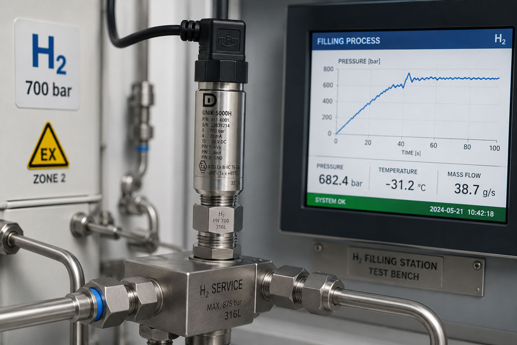
During hydrogen refuelling, the pressure does not rise slowly and uniformly to a static final value. Valves open, storage banks are switched and the mass flow is controlled according to the refuelling sequence. This creates rapid pressure ramps, short-term overshoots and significant temperature changes at the same time.
A pressure sensor may indicate a plausible value at the end of the refuelling process while still missing important events during the filling sequence. If the sensor is too slow, the signal is filtered too heavily or the control system acquires values too infrequently, short pressure spikes may appear attenuated or may not be detected at all.
For meaningful measurement, the sensor, process connection, output signal, analogue input, sampling rate and software filters must therefore be considered as one complete measuring chain. The key question is not only whether a sensor can measure 700 bar, but how reliably it detects rapid changes under the actual temperature and installation conditions.
Suitable sensors can be found in the H² pressure sensors category. Additional components for storage, refuelling, flow measurement and service points are grouped together in the H² hydrogen applications section.
Contents
- Why is pressure measurement during refuelling dynamic?
- Correctly classifying 350 and 700 bar systems
- Distinguishing between pressure-rise rate and pressure spikes
- Sensor response time and frequency response
- Sampling rate and filters within the measuring chain
- Selecting the measuring range and overload capability
- Using pulsation damping correctly
- Temperature rise and temperature compensation
- Process connection, dead volume and installation point
- Synchronously recording pressure, temperature and flow
- Typical errors in dynamic H₂ pressure measurement
- Practical example: Pressure spike when switching a storage bank
- Recommended commissioning procedure
- Which products are suitable?
- Conclusion
- Frequently asked questions
Why is pressure measurement during refuelling dynamic?
During refuelling, compressed hydrogen flows from the filling station storage system through valves, pipework, the cooler, hose and coupling into the vehicle tank or test vessel. The pressure profile is influenced by several factors:
- initial pressure and volume of the vessel being filled,
- pressure level of the storage bank being used,
- valve position and pressure control,
- mass flow and pipe cross-section,
- temperature of the hydrogen and the tank,
- switching between several storage stages,
- dead volume between the sensor, valve and tank.
The pressure can therefore increase significantly within a short period. When a valve opens or switches, a short overshoot may also occur. A static check before and after the filling process is not sufficient if the actual pressure profile is to be assessed.
Correctly classifying 350 and 700 bar systems
The designations 350 bar and 700 bar usually describe the nominal pressure level of the storage system. They are not automatically equal to the maximum pressure that may occur at every measuring point within the refuelling system.
On the filling-station side, storage vessels, compressors and sections of pipework may operate at higher pressures to transfer hydrogen into the vehicle tank. Dynamic overshoots, temperature conditions and permissible operating limits must also be taken into account.
The sensor range must therefore not be selected solely according to the H35 or H70 designation. The following information is required for each measuring point:
- normal operating range,
- maximum controlled pressure,
- possible pressure in the event of a fault or valve malfunction,
- short-term dynamic pressure spikes,
- permissible overload and burst pressure of the sensor,
- required resolution within the normal operating range.
A very large measuring range provides additional reserve, but with the same output span it also reduces the usable signal change per bar. A sensor with a range up to 1,000 bar provides less usable resolution within a 350 bar application than a correctly selected sensor with a lower full-scale value.
Distinguishing between pressure-rise rate and pressure spikes
The pressure-rise rate describes how quickly the pressure changes during a defined period. It may be specified, for example, in bar per second or MPa per second.
A pressure spike, by contrast, is a short-term maximum value that may be significantly higher than the actual pressure ramp. Typical causes include:
- rapid opening of a valve,
- switching between storage banks,
- control-valve overshoot,
- pulsation from compressors or pressure boosters,
- gas volume within long measuring lines,
- resonance within the pipework and measuring connection.
For process control, the smoothed pressure profile may be decisive. For component testing, root-cause analysis and overload assessment, however, short spikes must also remain visible. The two tasks may therefore require different filter settings or separate measuring channels.
Sensor response time and frequency response
The response time describes how quickly the output signal follows a pressure change. The frequency response indicates the frequency range over which pressure fluctuations are transmitted with a defined quality.
A sensor with high static accuracy is not automatically suitable for rapid pressure profiles. Conversely, a sensor with a very high bandwidth is not necessarily required for a slowly changing process indication.
The following questions should be clarified during selection:
- How long does the complete filling process take?
- How quickly can the valves and controllers switch?
- What is the shortest pressure spike that must still be detected?
- Is only the filling profile being examined, or also the dynamic control behaviour?
- What bandwidth do the sensor and output electronics provide?
- What delay is introduced by the analogue input and data logger?
The slowest component determines the behaviour of the complete measuring chain. A fast pressure sensor provides no benefit if the analogue input processes only a few values per second or the software heavily smooths the signal.
Sampling rate and filters within the measuring chain
The sampling rate specifies how frequently the output signal is acquired digitally. It must be significantly higher than the speed of the pressure change being investigated. Otherwise, a short pressure spike may occur between two measuring points and remain completely undetected.
The following filters may also influence the signal:
- internal filtering within the pressure sensor,
- hardware filters within the analogue input,
- averaging within the PLC,
- moving averages within the data logger,
- display filters within the visualisation system,
- subsequent smoothing during data analysis.
Every filter stage reduces interference, but also increases the response time. Unfiltered raw data should therefore be available at least during commissioning or fault analysis.
The display update rate must also not be confused with the actual measuring rate. A curve on the screen may be updated only ten times per second even though the values are recorded internally at a much higher rate, or vice versa.
Selecting the measuring range and overload capability
The measuring range must cover the normal filling profile with sufficient reserve. The three specifications measuring range, overload capability and burst pressure must be clearly distinguished.
- Measuring range: range within which the specified measuring accuracy applies.
- Overload capability: short-term permissible pressure at which the sensor should not suffer permanent damage.
- Burst pressure: pressure limit of the mechanical pressure containment; this is not a permissible operating condition.
A sensor must not be operated regularly above its measuring range merely because its overload capability is higher. Frequent pressure cycles close to the mechanical load limit may influence service life and long-term stability.
The pressure reference and output range must also be considered during sizing. For high-pressure gaseous hydrogen, absolute pressure or sealed-gauge pressure is often used. The exact version must match the measuring task.
Using pulsation damping correctly
Restrictors, snubbers and long measuring lines can attenuate rapid pressure changes. This may be useful if the sensor must be protected against high-frequency compressor pulsations or if a stable control value is required.
When analysing a refuelling ramp, however, the same damping may be disadvantageous:
- pressure spikes appear lower,
- the measured maximum occurs later,
- valve-switching events are barely visible,
- the sensor continues to indicate an outdated value after the valve has closed,
- pressure differences between the measuring point and the tank increase.
Damping should therefore not be applied as a general measure. It must first be clarified whether the sensor is intended to provide a stable process value or reproduce the actual dynamics with as little distortion as possible.
Two separate measuring paths may be useful for control and diagnostics: a specifically filtered channel for the controller and a fast channel for recording and peak-value analysis.
Temperature rise and temperature compensation
During rapid filling of a storage vessel, the gas temperature increases. At the same time, pre-cooled hydrogen, cold pipework and a significantly warmer sensor environment may influence the measuring point.
Temperature affects the pressure measurement on several levels:
- temperature-dependent measuring error of the sensor,
- temporary temperature gradient between the gas and sensor housing,
- changes in density and tank condition,
- thermal expansion of pipes and connections,
- different temperatures of the electronics and process diaphragm.
The stated temperature compensation of a sensor applies within a defined range and under specified test conditions. During a rapid transition between pre-cooled hydrogen and a warm environment, temporary thermal effects may occur that are not fully represented by a purely static calibration.
Pressure and gas temperature should therefore be recorded together when assessing the filling process. Subsequent interpretation of the pressure profile without temperature data is possible only to a limited extent.
Process connection, dead volume and installation point
A fast sensor can only measure rapidly if the pressure change reaches its diaphragm without unnecessary delay. Long, narrow branch lines or adapters with a large dead volume can act as a pneumatic low-pass filter.
The following are important for dynamic measuring points:
- a short pressure channel with sufficient diameter,
- the lowest possible dead volume,
- a suitable hydrogen-compatible process connection,
- a defined metallic seal or approved sealing system,
- no unnecessary combination of several adapters,
- installation without mechanical stress,
- an accessible position for leak testing and replacement.
The measuring point must also correspond to the measurement objective. A sensor installed upstream of the control valve indicates the supply pressure, but not necessarily the actual pressure inside the vehicle tank. Pressure losses and dynamic differences may exist between the two points.
Synchronously recording pressure, temperature and flow
A complete assessment of the refuelling process often requires several measured variables:
- pressure upstream and downstream of the control valve,
- pressure at the storage vessel or close to the tank,
- hydrogen temperature,
- mass flow,
- valve position and switching times,
- tank and ambient temperature.
All channels should use a common time base. If pressure and temperature are recorded by separate systems with different clocks, short events are difficult to correlate reliably afterwards.
The data acquisition system should therefore document:
- sampling rate of each channel,
- timestamps and synchronisation,
- configured filters,
- measuring range and unit,
- calibration status of the sensors,
- valve and controller states.
Typical errors in dynamic H₂ pressure measurement
| Error | Possible consequence | Suitable measure |
|---|---|---|
| Sensor selected only according to final pressure | Pressure spikes and overload reserve are not considered adequately | Assess the complete operating and fault-pressure range |
| Sampling rate too low | Short overshoots remain invisible | Adapt the measuring rate to the fastest relevant events |
| Software filtering too strong | Pressure ramp appears slower and smoother than it actually is | Store raw data and document all filters |
| Long, narrow branch line | Delayed and attenuated pressure profile | Install the sensor as close to the process as possible |
| Standard pressure sensor without H₂ verification | Unsuitable materials, seals or approvals | Check the exact sensor version for hydrogen compatibility |
| Only pressure is recorded | Thermal effects cannot be evaluated | Record pressure, temperature and flow synchronously |
| Overload capability used as the measuring range | Sensor is operated permanently outside its specification | Assess measuring range and overload limit separately |
| Incorrect analogue scaling | PLC systematically displays the wrong pressure | Check the output signal and scaling using a reference signal |
Practical example: Pressure spike when switching a storage bank
On an H₂ test bench, a 700 bar storage system is filled through several pressure stages. The installed pressure transmitter provides a stable 4–20 mA signal. The recorded pressure curve shows a smooth ramp without any noticeable overshoot.
During repeated tests, however, an independent overpressure monitoring system trips immediately after a storage bank is switched. The pressure stored in the PLC remains below the trip threshold.
The measuring chain is then inspected. The sensor is sufficiently fast, but the analogue input operates with strong input filtering. In addition, the PLC calculates an average across several measured values. The short pressure spike is therefore heavily attenuated.
A separate fast measuring channel is installed for further investigation. The sensor, analogue input and data logger are operated at a higher measuring rate, while the raw data are stored without filtering. A short pressure overshoot immediately after valve switching now becomes visible.
The valve ramp is adjusted and the switching sequence optimised. The filtered channel remains in use for process indication, while the fast channel is used for monitoring and documentation.
This example shows that not only the pressure sensor, but the slowest or most heavily filtered component determines which pressure spikes are ultimately visible.
Recommended commissioning procedure
- Document the normal, maximum and possible fault pressure for each measuring point.
- Define the required pressure-rise rate and shortest relevant event duration.
- Check the hydrogen compatibility of the materials, diaphragm, seal and connection.
- Select the measuring range, overload capability and pressure reference.
- Check the response time or frequency response of the sensor.
- Select an output signal suitable for the required dynamics.
- Check the sampling rate and hardware filters of the input.
- Document software filters and averaging functions.
- Install the sensor using a short pressure channel and low dead volume.
- Perform a professional leak test after installation.
- Synchronise pressure, temperature, flow and valve signals.
- Check the measuring range and scaling of the data acquisition system.
- Initially perform the filling process under controlled conditions.
- Evaluate the raw data, peak values and timing relationships.
Which products are suitable?
H² pressure sensors
The H² pressure sensors category includes different sensor solutions for hydrogen storage systems, compressors, refuelling stations, test benches and fuel-cell systems.
When selecting a sensor, the pressure range, dynamics, temperature range, output signal, materials, process connection and, where applicable, explosion-protection or automotive approvals must be considered together.
UNIK 5000H
The UNIK 5000H is a configurable pressure sensor with hydrogen-compatible wetted materials. It is particularly suitable for dynamic measurements, test benches and hydrogen-mobility applications where rapid analogue pressure acquisition is required.
Depending on the configuration, different pressure ranges, pressure references, output signals, electrical connections and approval options are available. The complete ordering configuration must be checked for the specific refuelling measuring point.
HT-H2 series
The HT-H2 series provides hydrogen-compatible pressure sensors with measuring ranges up to 1,000 bar. Available options include 4–20 mA, voltage and ratiometric output signals as well as different process and electrical connections.
The series is suitable for hydrogen storage, hydrogen production, fuel-cell systems and refuelling applications. The required dynamic performance must be confirmed for the specific device version and measuring chain.
Additional H² components
The H² hydrogen applications section also contains solutions for temperature, flow, level measurement and measuring or service connections. These components allow the pressure profile, thermal condition and transferred hydrogen quantity to be assessed together.
Conclusion: The complete measuring chain must be fast enough
During hydrogen refuelling, it is not sufficient to measure only the static final pressure correctly. Pressure ramps, valve switching and short-term overshoots may be decisive for process control, component protection and documentation.
The pressure sensor must be suitable for the hydrogen, pressure range, temperature range and required dynamics. A short process connection, sufficient sampling rate and controlled filter settings are equally important.
Excessive damping can conceal pressure spikes. Insufficient damping, by contrast, may transmit high-frequency interference and compressor pulsations unnecessarily strongly into the controller. Filtering must therefore be defined specifically for the measuring task.
Pressure, temperature, flow and valve signals should be recorded synchronously. Only a combined assessment can show whether an anomaly was caused by the actual filling process, a thermal effect or the measuring chain.
Frequently asked questions about pressure measurement during hydrogen refuelling
Is a pressure sensor with a range up to 700 bar sufficient for a 700 bar system?
Not automatically. The maximum operating pressure, filling-station supply pressure, dynamic spikes and required overload reserve must be considered for the specific measuring point.
Which is more important: Accuracy or response time?
This depends on the measuring task. Accuracy may be the priority for the final pressure and balancing. For valve switching and pressure spikes, response time, frequency response and sampling rate are equally important.
Why does the sensor not indicate a pressure spike even though the overpressure monitor trips?
Possible causes include an insufficient sampling rate, heavy filtering, averaging or a long branch line. Different installation points may also detect different maximum pressures.
Should a pressure snubber be used during refuelling?
Only after the measuring task has been assessed. A pressure snubber can stabilise the sensor and control signal, but it may also conceal exactly the short pressure spikes that need to be investigated.
Why must the temperature be measured at the same time?
The gas temperature changes significantly during rapid filling. It influences the condition of the tank, the hydrogen density and the thermal behaviour of the pressure measuring point.
Is a 4–20 mA signal suitable for rapid pressure measurements?
In principle, a 4–20 mA signal can also transmit dynamic pressure changes. However, the decisive factors are the bandwidth of the sensor, the load within the current loop, the analogue input, its filtering and the sampling rate of the data acquisition system.
Where should the pressure sensor be installed?
The installation point depends on the measuring task. For tank pressure, the measuring point should be located as close as possible to the relevant storage vessel. A sensor upstream of a control valve primarily measures the supply pressure.